


 Loading...
PRS-2 REFRIGERATION SYSTEMS
Installation, Operation and
Maintenance Instructions
TABLE OF CONTENTS
INSTALLATION |
|
2 - 7 |
|||||||||||||||
Wall Mounted Systems |
2 - 3 |
||||||||||||||||
General Instructions |
|
|
|
|
|
|
|
|
|
|
2 - 3 |
||||||
Freezer Models 100 |
or 150 |
3 |
|||||||||||||||
Ceiling Mounted Systems |
|
|
|
|
|
|
4 - 6 |
||||||||||
General Instructions |
|
|
|
|
|
|
|
|
4 - 5 |
||||||||
Outdoor Systems Utilizing a Membrane Roof |
5 - 6 |
||||||||||||||||
OPERATION |
|
|
7 - 9 |
||||||||||||||
Standard Temperature (Cooler) Systems |
7 |
||||||||||||||||
Low Temperature (Freezer) Systems |
|
|
|
7 - 9 |
|||||||||||||
|
|
|
|
|
|
|
|
|
9 |
||||||||
Extra Low Temperature (Freezer) Systems |
|||||||||||||||||
MAINTENANCE |
|
|
10 - 11 |
||||||||||||||
General |
10 |
||||||||||||||||
Service |
and Analysis Guide |
|
11 |
||||||||||||||
DIXELL CONTROLLER SETTINGS FOR STANDARD PRS-2 |
|
||||||||||||||||
MODELS |
|
12 |
|||||||||||||||
DIXELL CONTROLLER SETTINGS FOR CPF060DC-A |
|
||||||||||||||||
MODEL |
|
13 |
|||||||||||||||
DIXELL XR01-02CX CONTROLLER MANUAL |
|
14 |
|||||||||||||||
DIXELL XR01-02CX CONTROLLER MANUAL |
|
24 |
|||||||||||||||
ELECTRICAL DATA |
|
||||||||||||||||
Electrical and Refrigerant information can be found on the
Serial Tag.
7/10 Rev. B 040086

INSTALLATION
WALL MOUNTED SYSTEMS
General Installation Instructions
Note: If the system to be wall mounted is a freezer model 100 or 150, please see the next section with special instructions on mounting these units.
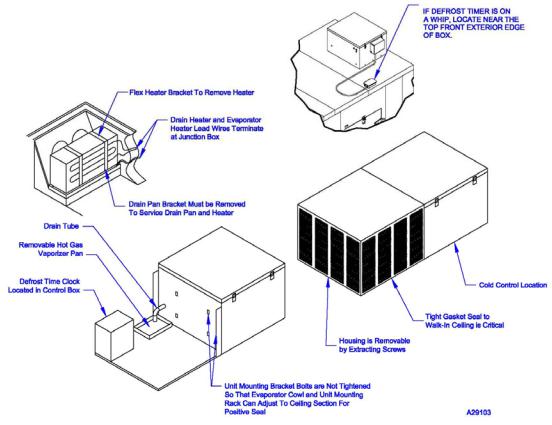
Carefully raise the entire refrigeration system and insert the projecting sleeve of the evaporator section into the opening of the walk-in wall. While supporting the system, lock it into position by turning the locks exactly as you did when locking the walk-in sections together. Make sure that the locks are positively engaged and insert the plug buttons into the lock access holes when finished. Refer to Figure 1.
Note: Some motor compressors are openly spring mounted to absorb vibration. Be sure that these bolts are loosened to permit the compressor to float freely on the springs. A reminder label is applied to systems where this procedure applies.
All systems require a permanent connection to an electrical service and a connection at the junction box located within the condensing unit housing. Refer to the serial tag for all pertinent electrical data. These systems must be connected to a power supply disconnect switch and wired according to local and national electric codes.
Wall Mounted PRS-2 Refrigeration System
Figure 1
2

No plumbing drain is required, under normal conditions, for indoor installations. A built-in hot gas vaporizer dissipates the condensate moisture automatically. In outdoor installations, the condensate should be plumbed to the nearest drain. Check local building codes. Outside drain lines must also be wrapped with a suitable heater wire if they are ever subjected to below freezing temperatures. Outdoor installations also require the attachment of the rain hood that will divert rainfall from the upper surface of the evaporator housing. See Figure 1 for an illustration.
Be sure to allow for sufficient airflow around the condenser. A minimum clearance of two feet is required for proper unit operation. If multiple units are located in the same area, be sure they do not exhaust hot air flows into one another.
Please see the section “Instructions for Pre-Charged Lines” if the installation of this system involves the use of pre-charged lines to connect the evaporator and condenser sections.
Freezer Models 100 or 150
1.After uncrating, before attempting to attach the refrigeration system to the walk-in, a substantial temporary support should be built. The support should be approximately 28 inches high and placed directly below the wall opening of the walk-in.
Note: Due to the weight of these systems it is highly recommended that proper lifting equipment, such as a fork truck, be utilized during installation.
2.Lift the refrigeration system onto the temporary support. Determine whether the coil section sleeve is positioned properly so that it can be inserted into the opening without being bent or damaged. Shim the system appropriately so that this can be accomplished.
3.Carefully slide the entire system so that the coil section sleeve enters the opening without disturbing the temporary support below the refrigeration system. Continue until the gasket around the coil section contacts and seals around the entire perimeter of the coil section. Shim the system and adjust it accordingly so that the gasket seal will be uniform on all four sides.
4.Using the section-latching wrench provided for the erection of the walk-in, insert the wrench into the latch access holes of the coil section. Turn each of the locks clockwise until the latches engage the strikes in the walk-in. Turn the lock until a full stop is encountered. DO NOT REMOVE THE TEMPORARY
SUPPORT!
5.Remove the louver assembly and drill four 9/16” diameter holes through the two upright angles of the condensing unit section. Drill completely through the walk-in wall and insert the 1/2" threaded nylon rods. Secure with the flat washers and nuts provided. Refer to Figure 2.
6.With the leveling screws threaded completely into the leg support, insert the leg support into the leg retainers at the outer corners of the condensing unit section. Unscrew the leg leveling screws until they contact the floor or other supporting surface. Note: If the supporting surface is extremely uneven, suitable shimming material must be provided under one or both of the leg supports.
7.Attach the diagonal leg support braces using the threaded fasteners provided. Make the final adjustments to the leg leveling screws so that they serve as supporting devices to the outer edge of the refrigeration system.
8.Insert plug buttons into each of the latch access holes.
Figure 2
9. Remove the temporary support assembly that was provided in Step 1.
3
CEILING MOUNTED SYSTEMS
General Installation Instructions
This section has the general instructions for installing the ceiling mounted Refrigeration System. Before proceeding, please also see the following sections on mounting “Outdoor Systems Utilizing a Membrane Roofing Material”, or “Remote Systems with Curb and Electric Vaporizer”, if applicable.
Note: Due to the weight of these systems, it is highly recommended that proper lifting equipment, such as a fork truck, be utilized during installation. Also, be sure to allow for sufficient airflow around the condenser. A minimum clearance of two feet is required for proper unit operation. If multiple units are located in the same area, be sure they do not exhaust hot air flows into one another.
1.Mount eyebolts to the base of the refrigeration system through the holes that were used to lag the base to the shipping crate. Note: The holes can be drilled out to a larger diameter, if required, for eyebolts that are available.
2.Insert chains or cables from an overhead lifting source through the eyebolts and carefully raise the entire refrigeration system to the top of the walk-in.
3.Position the unit cooler section of the refrigeration system over the hole in the walk-in ceiling section.
4.Align the tabs on the side of the unit cooler section with the predrilled holes in the ceiling section. Before proceeding to the next step, the cowl cover should be removed. Look inside the unit cooler section and be sure the air divider in the ceiling section lines up with the black gasket divider in the unit cooler. Simply bending the ceiling section divider slightly forward or backward may be required. This will prevent any short cycling of discharge and return air.
5.Fasten the unit cooler section down to the ceiling using the provided drive screws, which can be found in the small cloth bag. CAUTION! This must be done to prevent the entire refrigeration system from moving during operation.
Note: On smaller refrigeration systems, you may elect to install the system on the ceiling section while the section is still on the floor. CAUTION! Make sure to fasten down the system to the ceiling panel. The ceiling section and the refrigeration system may then be erected together in the normal sequence of assembly as shown in the walk-in installation instructions. This method is not practical and should not be used with larger systems of 1 horsepower or above, such as a model CPF100 or CPF150.
4
6.After the system is in place, make sure that the bolts fastening the condensing unit section to the evaporator section are loose enough so that the two sections can adjust to the ceiling surfaces. Note: On large systems, 1 horsepower and above, the units are placed on a rack assembly and do not have these bolts connecting the two sections together. No adjustment is necessary.
Note: Some motor compressors are openly spring mounted to absorb vibration. Be sure that these bolts are loosened to permit the compressor to float freely on the springs. A reminder label is applied to systems where this procedure applies.
7.All systems require a permanent connection to an electrical service and a connection at the junction box located within the condensing unit housing. Refer to the serial tag for all pertinent electrical data. These systems must be connected to a power supply disconnect switch and wired according to local and national electric codes. No plumbing drain is required, under normal conditions, since a built-in hot gas vaporizer dissipates the condensate moisture automatically.
Outdoor Systems Utilizing a Membrane Roofing Material
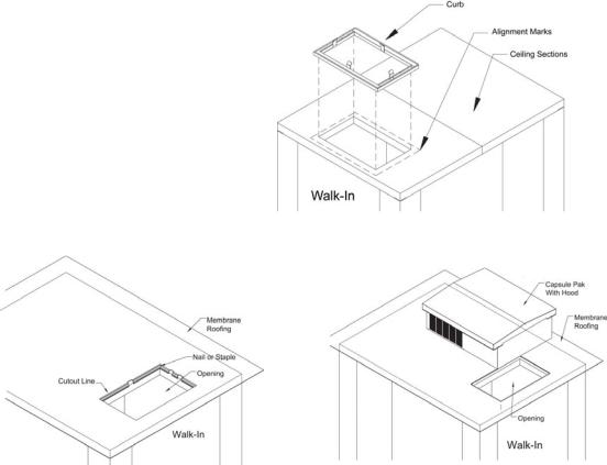
1.After the walk-in is completely assembled, place the curb face down on top of the ceiling sections, aligning the opening with the gasket on the curb. To insure proper opening alignment, mark the outside portion of the curb on the ceiling sections with a marking pencil.
2.Remove the paper from the gasket and position the curb, gasket side down, on the pencil line. Press down firmly. Note: Movement of the curb is very difficult after the gasket adheres to the ceiling section. Refer to Figure 3.
Figure 3
Figure 4 |
Figure 5 |
3.Lay the membrane roofing material over the walk-in ceiling sections and curb leaving a six inch overhang on all four sides of the walk-in. Using an utility knife, cut a hole in the membrane roof approximately 1-1/2” in from the edge of the opening. (The resulting hole in the membrane will be smaller than the ceiling opening). Fold the 1-1/2” membrane flaps into the opening, notching the membrane around the locators and divider. Use either staples, roofing nails, sheet metal screws, caulk, glue, etc. to fasten the membrane roofing material to the inside edge of the curb frame. Refer to Figure 4.
5
4.Set the PRS-2 Refrigeration System over the opening in the curb. Remove the enclosure from
the condensing unit portion of the system and drill two 9/16” holes through the system base, membrane roof material, curb, and the foamed ceiling section. The holes should be located on opposite sides of the unit. Insert one 1/2” threaded nylon rod into each hole and place one washer and nut on the condensing unit end of the threaded nylon rod. Place a second washer and nut on the inside of the walk-in and tighten securely. Replace the enclosure and attach the outdoor hood with the drive screws provided. Refer to Figure 5. The nylon rods, washers, and nuts are provided.
Figure 6 |
Figure 7 |
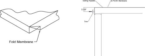
5.Fold all four corners of the membrane roofing material over the walk-in corners as shown in Figure 6.
6.Attach the trim and door hood by using the provided hex head sheet metal screws. All pieces should be held down 3-1/8” from the ceiling top as shown in Figure 7. Insure the trim and membrane roof material cover the joint between the ceiling and wall panels. Note: The trim may have to be cut to fit.
7.Trim off all excess membrane roofing material on the bottom of the aluminum trim using a utility knife.
Note: In outdoor installations, the condensate should be plumbed to the nearest drain. Check local building codes. Outside drain lines must also be wrapped with a suitable heater wire if they are ever subjected to below freezing temperatures.
6
OPERATION
STANDARD TEMPERATURE (COOLER) SYSTEMS
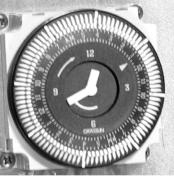
The automatic air defrost Refrigeration System for coolers is a basic, unitized refrigeration system. The system is designed to provide normal storage temperatures in the Walk-in with a minimum of effort during initial installation. The system consists of a complete condensing unit, an evaporator coil, a method for controlling the temperature, and a time switch for setting "off cycle" defrost. The time switch used to control the defrost cycle has been factory preset. However, please refer to the following instructions on the operation of the time switch if an adjustment is ever needed. All cooler systems are provided with an electronic 24 hour dial time clock. Note: The cooler time clock is factory set for a 15 minute defrost every 3 hours. Important: It is the installing contractor’s responsibility to check the operation upon start-up and make necessary temperature control or thermal expansion valve adjustments as required for proper operation.
Note: Refrigeration Systems that are designed for outdoor installation will be fitted with electric crankcase heaters, electrically heated condensate drain tubes, automatic head pressure control valve, and the "pumpdown cycle".
Programming
The 24-hour dial has quarter-hour divisions and AM/PM indications. The time switch is programmed by pushing the captive trippers to the outer ring position for the entire period that the load is to be turned "on", i.e. fifteen minutes for each tripper on the 24-hour dial. When the tripper is pushed to the inside, the switch is in the "off" position. (It is not recommended for the cooler to have defrosts longer than 15 minutes.)
Defrost Cycle (Cooler System)
The purpose of the defrost cycle is to allow time for any frost formed on the evaporator to melt and clear from the surface. The time clock stops the condensing unit. During this time, the evaporator fans continue to run, blowing 35-38°F air over the fins. This process will warm the evaporator above 32°F. After 15 minutes, the condensing unit should restart.
LOW TEMPERATURE (FREEZER) SYSTEMS
The low temperature, automatic electric defrost Refrigeration System is the most dependable, readily understood equipment available. It employs a basic refrigeration system with electric elements to provide heat for defrosting.
Important: It is the installing contractor’s responsibility to check the operation upon start-up and make necessary temperature control or thermal expansion valve adjustments as required for proper operation.
Note: Refrigeration Systems that are designed for outdoor installation will be fitted with electric crankcase heaters, electrically heated condensate drain tubes, automatic head pressure control valve, and the "pumpdown cycle".
Note: If you purchased a CPX150DC or CPX151DC extra low temperature system, please also refer to the instructions under “Extra Low Temperature Systems” as all of the following operations may not pertain.
Note: Some models may have a programmable control used in place of the time switch. This unit is used to control the temperature and the defrost settings. Please see the separate instructions that are included on the operation of this control.
7
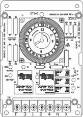
Time clock adjustments:
Setting the correct time of day - To set the correct time of day simply rotate the small inner dial counterclockwise until the correct time of day on the large dial is opposite the "time" indicator. Number of defrosts per day - The timer is factory set to defrost the evaporator four times a day. If more defrosts are required, remove a knurled slotted screw from the holder, insert the screw into the time slot on the large dial where a defrost is desired, and tighten. Defrost length adjustment - On the small, upper dial there is a pointer that is used to set a 100% fail-safe feature. The fail-safe of the timer is factory set at 30 minutes. The function of this device is to terminate the defrost if a system malfunction occurs during defrost.
WARNING ! No adjustment of this device should ever be necessary.
Lengthening the fail-safe time will not lengthen the defrost cycle.
Defrost Cycle (Freezer System Only)
Under low temperature conditions, the air being forced through the evaporator coil is well below freezing at all times, even during each compressor "off" cycle. Therefore, a source of heat must be supplied to melt the accumulated frost. To achieve a complete defrost, electric heater elements are attached to the evaporator coil and to the drain pan. An electric time switch initiates a predetermined number of regular defrost periods per day. When a defrost period occurs, the time switch stops the evaporator fan(s) and the condensing unit, and energizes the electric heaters in the evaporator coil and in the drain pan beneath it.
Defrost Cycle Termination
As the defrost cycle progresses and the frost accumulation melts from the fins of the evaporator coil, the temperature of the finned surfaces of the evaporator coil will rise proportionately with the removal of the frost. When this temperature reaches about 50°F, a point where the evaporator coil should be completely free of frost, a defrost termination thermostat attached to the evaporator coil will energize a solenoid coil in the defrost time switch which will revert the system to the cooling cycle. The fan(s) in the evaporator housing will not start, however, until the fan delay cycle has expired. See the "Fan Delay" below.
Fan Delay
When a defrost cycle is terminated through the action of the defrost termination thermostat as described in the section "Defrost Cycle Termination", the electric defrost heaters are de-energized, the compressor starts, and evaporation resumes in the coil. The evaporator fan(s), however, will not start until the evaporator coil temperature is reduced to about +20°F. Once this temperature is reached, the fan delay switch action of the defrost termination thermostat energizes the evaporator fan(s) and they begin operating.
The fan delay feature is an important part of defrosting. If the fan(s) was permitted to start immediately following a defrost period, the heat that accumulated in the evaporator housing would be circulated throughout the walk-in, raising the temperature considerably. In addition, any droplets of moisture that remained clinging to the fins of the evaporator coil would be blown into the storage space. The fan delay feature provides for a short refrigeration cycle WITHOUT the evaporator fan(s) to prevent these conditions.
Note: During the initial startup of a PRS-2 Refrigeration System on a warm walk-in, the evaporator
fan(s) will not start until the evaporator coil reaches and maintains +20°F. Further, the evaporator fans may cycle "on" and "off" several times until the evaporator coil reaches and maintains +20°F.
Refrigeration Controller
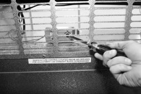
All Refrigeration Systems up to and including 100 series, designed for indoor installations, are equipped with conventional temperature thermostats that sense the "cut-in" and "cut-out" temperatures of the return air to the evaporator coil. These thermostats are adjustable and require a turn of the dial to change the interior storage temperature. Note: The control can be reached through the interior louver for adjustment, with a 6” long shaft flat blade screwdriver. Make adjustments in small increments until the desired temperature is reached.
Note: Some models may have a programmable control used in place of the time switch. This unit is used to control the temperature and the defrost settings. Please see the separate instructions that are included on the operation of this control.
8
All low temperature 150 series refrigeration systems, for indoor and outdoor installation, employ a "pump-down cycle" which permits the compressor to pump most of the refrigerant from the evaporator into its receiver after each "on" cycle. In this application, the refrigeration controller regulates the operation of a solenoid valve in the liquid line. A low-pressure control is installed in the low side of the system that shuts down the compressor due to low pressure, which results when the solenoid valve closes the liquid line. The temperature thermostat is adjustable and requires a turn of the dial to change the interior storage temperature.
Drain Tube Heater
All low temperature, ceiling mounted Refrigeration Systems employ a low wattage, electric heater strip. This heater is spirally wound around the condensate drain tube that extends from the drain pan below the evaporator coil to the evaporator section housing wall. This heater is energized continually to provide positive discharge of the condensate moisture to the hot gas vaporizer. The heater and drain tube are covered with an insulated tape.
EXTRA LOW TEMPERATURE SYSTEMS – CPX150DC & CPX151DC
These units are equipped with a “Hot Gas By-Pass” defrost system. Defrosting of the evaporator coil and evaporator drain pan is accomplished by pumping hot refrigerant gas directly into the drain pan defrost loop and the evaporator coil bypassing the condenser.
A programmable control is used in place of a time switch in these models to control the temperature and the defrost settings. The programmable control can be found mounted to the control box under the condensing unit cover. The control is preset at the factory for the operating temperature and the number of defrosts. Please see the separate instructions that are included on the operation of this control.
Note: Some models may have a programmable control used in place of the temperature control. This unit is used to control the temperature and the defrost settings. Please see the separate instructions that are included on the operation of this control.
9
MAINTENANCE
WARNING: When servicing any Refrigeration System or performing any maintenance procedure, always disconnect the main power supply.
The condensing unit, condensate vaporizer, and the control box on low temperature models are all accessible by removing the grills or louvers on the condensing unit housing. The evaporator coil section is accessible by unlatching and removing the evaporator section housing cover. For access to the fan blade(s) and for oiling the fan motor on some models, remove the louver on the walk-in ceiling.
Cleaning the Condenser
The efficiency of the condensing unit, to a great extent, depends upon the passage of air freely through the condenser. For this reason, the condensing unit should be as clean as possible at all times and should always have an unrestricted supply of air.
Cleaning the condenser should be done at a minimum of every 3 months.
A wire brush should be used to loosen the
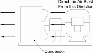
accumulation of dust and dirt particles that have attached to the fins of the condenser. Once this accomplished, a vacuum cleaner can be used to remove the loosened particles. If compressed air is used to clean the condenser, the air should be directed through the condenser from the fan motor side. Wipe away any accumulated dust from the compressor motor and related parts.
Lubrication
The evaporator fan motor(s) on ceiling mounted systems 100 series and larger, should be oiled with a good grade of S.A.E. #20 oil every six months. Evaporator fan motors on ceiling mounted systems less than 100 series and on the ceiling mounted CPX100 model do not require additional oiling.
Evaporator Drain Pan Removal - Ceiling Mounted Models
Remove the drain pan retainer that is located near the end of the drain pan opposite the drain tube. It is secured by a thumbscrew. Release the drain tube stub from the drain discharge tube and remove the pan. On freezer models, a drain pan heater is secured to the drain pan bottom by short brackets. Only a slight effort is required to release the heater element from the brackets. When replacing the drain pan, make sure that the drain pan stub is properly connected to the drain discharge tube. When replacing the drain pan, the drain tube must be siliconed to prevent water leakage.
Hot Gas Vaporizer Pan
Condensate from the evaporator pan is discharged into a hot gas vaporizer pan, which is located in the condensing unit housing. Here the hot discharge gas from the compressor elevates the temperature of the water and it vaporizes into the atmosphere. This pan should be cleaned periodically to remove solids that remain after the moisture is evaporated.
10
Loading...