

Norgren L74M Maintenance Manual
L74M, L74C
Installation & Maintenance
Instructions
ADJUSTMENT
1. Turn on system pressure.
2. Adjust lubricator drip rate only when there is a constant
rate of air flow thru the lubricator. Monitor drip rate thru
sight feed dome (6).
3. Oil-Fog Lubricators - Determine the average rate of flow
thru the lubricator. Turn slotted green rotator in sight
feed dome (6) to obtain one drop per minute for each 5
dm3/s (10 scfm). For example, if the average flow is 19
dm3/s (40 scfm), set the drip rate at 4 drops per minute.
Turn rotator counterclockwise to increase and clockwise
to decrease the drip rate. Total travel of rotator is 320°.
4. Micro-Fog Lubricators - Determine the average rate of
flow thru the lubricator. Turn slotted red rotator in sight
feed dome (6) to obtain the recommended drops per
minute. See
Drip Rate Chart
. Turn rotator
counterclockwise to increase and clockwise to decrease
the drip rate. Total travel of rotator is 320°.
Drip Rate Chart for Micro-Fog Lubricators
Flow - dm3/s (scfm) Drops per Minute
2.4 (5) 10
5 (10) 11
9 (20) 13
14 (30) 15
19 (40) 17
24 (50) 19
28 (60) 22
34 (70) 24
38 (80) 26
43 (90) 28
48 (100) 30
5. Monitor the device being lubricated for a few days
following initial adjustment. Adjust the drip rate if the oil
delivery at the device appears either excessive or low.
DISASSEMBLY
1. Shut off inlet pressure. Reduce pressure in inlet and
outlet lines to zero. Loosen fill plug (2).
2. Remove reservoir - push into body and turn
counterclockwise.
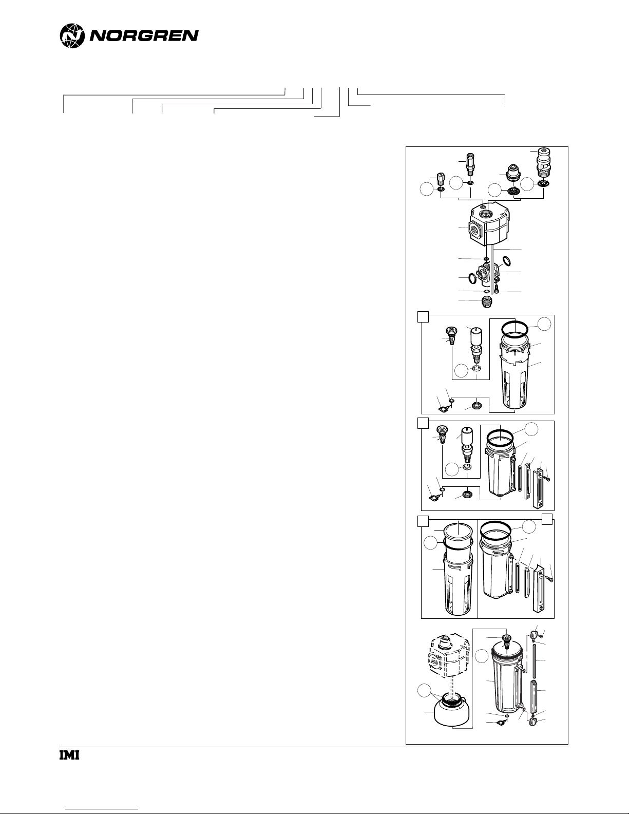
3. Disassemble in general accordance with the item
numbers on exploded view. Do not remove the manual
drain unless replacement is necessary. Remove and
replace drain assembly only if drain malfunctions. Do not
remove siphon tube (51). Remove and replace items 52
thru 57 only if lubricator malfunctions.
CLEANING
1. Clean plastic reservoir with warm water only. Clean other
parts using warm water and soap.
2. Dry parts. Blow out internal passages in body with clean,
dry compressed air.
3. Inspect parts. Replace parts found to be damaged. If
plastic reservoir shows signs of cracking or cloudiness,
replace with a metal reservoir.
ASSEMBLY
1. Lubricate o-rings, the portion of the manual drain body
(18, 28) that contacts the bowl, and the hole in the
manual drain body that accommodates the stem of drain
valve (19, 29) with o-ring grease.
2. Assemble lubricator as shown on exploded view.
3. Assemble the 1 litre (1 quart) liquid indicator parts (65,
66, 67, 68, 69, 70) to reservoir. Apply a 0.9 to 1.8 kg (2
to 4 pound) clamping force to upper and lower sight
glass brackets (66). Tighten screws (65).
3. Torque Table N-m (Inch-Pounds)
6, 8 (Dome) and 21, 31 (Nut) 2,3 to 2,8 (20 to 25)
34, 45 (Screw) 1,7 to 2,3 (15 to 20)
53 (Screw) 1,1 to 1,6 (10 to 14)
65 (Screw) 0,9 to 1,1 (8 to 10)
4. Push reservoir, or reservoir with guard, into body and
turn fully clockwise.
TECHNICAL DATA
Fluid: Compressed air
Maximum pressure:
Transparent bowl: 10 bar (150 psig)
Metal bowl: 17 bar (250 psig)
Operating temperature*:
Transparent bowl: -20° to +50°C (0° to +125°F)
Metal bowl: -20° to +80°C (0° to +175°F)
* Air supply must be dry enough to avoid ice formation at
temperatures below +2°C (+35°F).
Start point (minimum flow required for lubricator
operation) at 6,3 bar (90 psig) inlet pressure:
0,94 dm
3
/s (2.5 scfm)
Typical flow with 6,3 bar (90 psig) inlet pressure and 0,5
bar (7 psig) pressure drop: 70 dm
3
/s (148 scfm)
Nominal bowl size:
Standard: 0,2 litre (7 fluid ounce)
Optional: 1 litre (1 quart US)
Manual drain connection: 1/8"
Materials:
Body: Aluminum
Bowl:
Transparent with guard: Polycarbonate, steel guard
Metal: Aluminum
Metal bowl liquid level indicator lens:
0,2 litre (7 fluid ounce): Transparent nylon
1 litre (1 quart US): Pyrex
Sight-Feed dome: Transparent nylon
Elastomers: Neoprene and nitrile
REPLACEMENT ITEMS
Service kit (includes items circled
on exploded view) ..............................................4382-700
Liquid level lens kit
0,2 litre (7 fluid ounce) bowl (34, 36, 37, 38)....4380-050
1 litre (1 quart US bowl) (61, 65, 67 thru 70)......2273-22
Manual drain (18, 19, 20) (28, 29, 30) ......................619-50
INSTALLATION
1. Shut-off air pressure. Install lubricator in air line -
● vertically (reservoir down),
● with air flow in direction of arrow on body,
● Micro-fog and Oil-fog Uni-directional models:
upstream of cycling valves.
● Oil-fog Bi-directional models:
upstream or downstream of cycling valves.
● as close as possible to the device being lubricated,
● Oil-Fog Models - Not more than 5,2m (15 feet) from
the device being lubricated, and at the same height or
higher than the device.
2. Connect piping to proper ports using pipe thread sealant
on male threads only. Do not allow sealant to enter
interior of unit.
3. Push reservoir, or reservoir with guard, into body and
turn fully clockwise before pressurizing.
RECOMMENDED LUBRICANTS
Fill reservoir with a good quality, light, misting type oil for
compressed air tools. See Norgren publication
N/AL.8.900.935. Fill to maximum fill line on transparent
reservoirs. Oil level must always be visible in lens on metal
reservoirs. DO NOT OVERFILL.
FILL RESERVOIR (OIL-FOG LUBRICATORS)
Remove fill plug (2), add oil, and reinstall fill plug. Fill plug
can be removed and oil added without shutting off air
pressure to the lubricator.
FILL RESERVOIR (MICRO-FOG LUBRICATORS)
Shut off inlet air pressure and reduce pressure in reservoir
to zero. Remove fill plug (2), add oil, and reinstall fill plug.
Do not remove the fill plug when the reservoir is
pressurized, as oil will blow out the fill plug hole.
Micro-fog lubricators can be filled under pressure only if
equipped with the optional quick fill cap (4), which requires
a quick fill connector and oil pump.
IM-200.400.01
(4/98)
a subsidiary of IMI plc
© Norgren 1998
50
34
35
36
39
37
38
33
28
32
30
29
31
27
Current Metal Bowl
40
Early Plastic Bowl Early Metal Bowl
44
49
Current Plastic Bowl
17
26
25
24
23
22
18
20
19
21
45
46
48
47
42
41
43
Optional 1 Quart (1 Litre) Bowl
58
59
65
66
68
69
70
68
66
67
63
60
64
62
1
54
55
57
56
51
52
53
4
5
2
3
61
8
9
6
7
Micro-Fog® and Oil-Fog
Tool Lubricators
L74★ - ★★★ - ★★★
Thread Form
A....PTF
B....ISO Rc taper
G....ISO G parallel
Bowl
A....Optional 1 litre (1 quart US) metal
D....Metal with plastic liquid level indicator
P....Transparent with guard
R....Metal with Pyrex liquid level indicator
Options
N....None
P....Pyrex sight-feed dome
Q....Quick fill nipple
Drain
E....Closed bottom
Q....Manual, 1/4 turn
R....Remote fill
Air Flow Direction
E....Bi-directional (Oil-fog only)
P....Uni-directional
Type
C....Oil-Fog
M...Micro-Fog
Port
3....3/8"
4....1/2"
6....3/4"

WARNING
These products are intended for use in industrial
compressed air systems only. Do not use these products
where pressures and temperatures can exceed those listed
under
Technical Data
.
Polycarbonate plastic reservoirs can be damaged and
possibly burst if exposed to such substances as certain
solvents, strong alkalies, compressor oils containing esterbased additives or synthetic oils. Fumes of these
substances in contact with the polycarbonate reservoir,
externally or internally, can also result in damage. Clean
with warm water only
Use metal reservoir in applications where a plastic
reservoir might be exposed to substances that are
incompatible with polycarbonate.
In lubrication applications some oil mist may escape
from the point of use to the surrounding atmosphere.
Users are referred to safety and health standards for
limiting oil mist contamination and utilization of protecting
equipment
Before using these products with fluids other than air,
for nonindustrial applications, or for life-support systems
consult Norgren.
IM-200.400.02
(4/98)
a subsidiary of IMI plc
© Norgren 1998
L74M, L74C
Installation & Maintenance
Instructions
 Loading...