

Norgren B68G, B68E Maintenance Manual
B68G, B68E
Installation & Maintenance
Instructions
INSTALLATION
1. Install yoke in air line -
● with air flow in direction of arrow on top of yoke,
● upstream of lubricators and cycling valves,
● as close as possible to the device being served.
2. Connect piping to yoke ports using pipe thread sealant
on male threads only.
3. Install a pressure gauge in regulator or plug gauge ports.
Gauge ports can also be used as additional outlets for
regulated air.
4. Lubricate o-rings (15) with a light coat of o-ring grease,
then place o-rings in grooves in body (14).
5. Place clamp ring under lugs on top of yoke.
6. Make sure arrows on yoke and regulator point in same
direction, then plug regulator into yoke and tighten clamp
ring hand tight.
7. Turn bowl into body until arrowhead on bowl is aligned
with or to the right of the arrowhead on the body.
8. Flexible tube with 3mm (0.125") minimum I.D. can be
connected to the automatic drain. Avoid restrictions in
the tube.
ADJUSTMENT
1. Before applying inlet pressure to filter/regulator, turn
adjustment (1 or 7) counterclockwise to remove all force
on regulating spring (11).
2. Apply inlet pressure, then turn adjustment (1 or 7)
clockwise to increase and counterclockwise to decrease
pressure setting.
3. Always approach the desired pressure from a lower
pressure. When reducing from a higher to a lower
setting, first reduce to some pressure less than that
desired, then bring up to the desired pressure.
NOTE
With non-relieving filter/regulators, make pressure
reductions with some air flow in the system. If
made under no flow (dead-end) conditions, the
filter/regulator will trap the over-pressure in the
downstream line.
4. KNOB ADJUSTMENT. Push knob toward body to lock
pressure setting. Pull knob away from body to release.
Install tamper resistant cover and wire (see
Replacement Items) to make setting tamper resistant.
5. T-BAR ADJUSTMENT. Tighten lock nut (8) lock pressure
setting.
SERVICING
1. Open manual drain to expel accumulated liquids. Keep
liquids below baffle (53).
2. Clean or replace filter element when dirty.
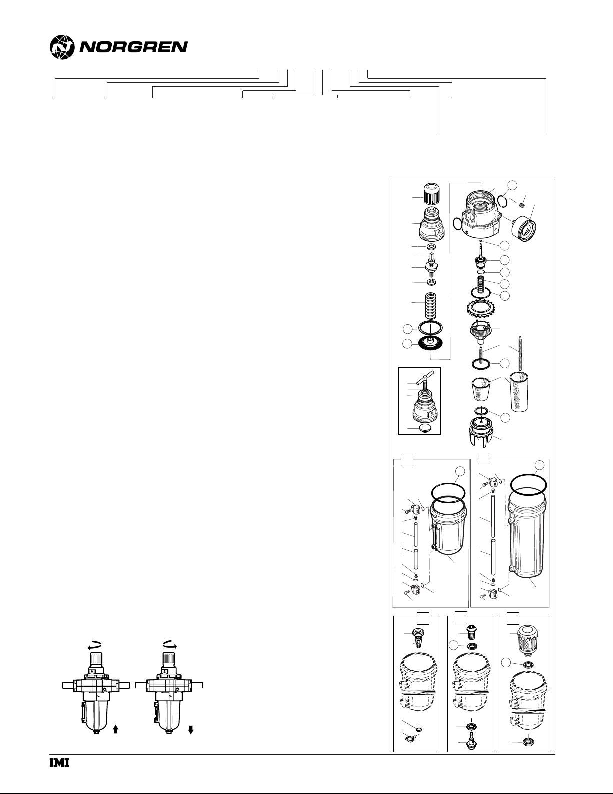
DISASSEMBLY
1. Shut off inlet pressure. Reduce pressure in inlet and
outlet lines to zero.
2. Turn adjustment (1 or 7) fully counterclockwise.
3. Unscrew clamp ring and remove unit from yoke.
4. Disassemble in general accordance with the item
numbers on exploded view. Do not remove the drains
unless replacement is necessary. Remove and replace
only if they malfunction.
CLEANING
1. Clean parts with warm water and soap.
2. Rinse and dry parts. Blow out internal passages in body
with clean, dry compressed air. Blow air through filter
element (55) from inside to outside to remove surface
contaminants.
3. Inspect parts. Replace those found to be damaged.
TECHNICAL DATA
Fluid: Compressed air
Maximum pressure: 17 bar (250 psig)
Operating temperature*: -20° to +80°C (0° to +175°F)
* Air supply must be dry enough to avoid ice formation at
temperatures below +2°C (+35°F).
Partical removal: 5, 25 or 40 µm
Air quality: Within ISO 8573-1, Class 3 and Class 5
(particulates)
Typical flow at 10 bar (150 psig) inlet pressure, 6,3 bar
(90 psig) set pressure and a droop of 1 bar (15 psig) from
set: 240 dm
3/
s (509 scfm)
1/4 turn manual drain connection: 1/8" pipe thread
Automatic drain connection: 1/8" pipe thread
Automatic drain operating conditions (float operated):
Bowl pressure required to close drain: Greater than 0,3 bar
(5 psig)
Bowl pressure required to open drain: Less than 0,2 bar
(3 psig)
Minimum air flow required to close drain: 1 dm3/s
(2 scfm)
Manual operation: Depress pin inside drain outlet to drain
bowl
Nominal bowl size:
0,5 litre (1 pint U.S.)
1 litre (1 quart U.S.)
Gauge ports:
1/8 PTF with PTF yoke ports
Rc1/8 with ISO Rc yoke ports
Rc1/8 with ISO G yoke ports
Materials:
Body: Aluminium
Yoke: Aluminium
Bonnet: Aluminium
Adjusting knob: Acetal resin
Optional T-bar adjusting screw: Steel
Valve: Aluminium
Bowl: Aluminium
Sight glass: Pyrex
Element: Sintered bronze or polypropylene
Elastomers: Synthetic rubber
REPLACEMENT ITEMS
Service kit (items circled on exploded view)
Relieving.............................................................4383-300
Nonrelieving .......................................................4383-301
0.5 litre bowl liquid level lens (19 thru 27) ............4380-060
1 litre bowl liquid level lens (30 thru 38) ...............4380-061
Filter element, 0.5 litre bowl, 5 µm (54, 55, 56) ......5576-97
Filter element, 0.5 litre bowl, 25 µm (54, 55, 56 ) ...5576-98
Filter element, 0.5 litre bowl, 40 µm (54, 55, 56) ....5576-99
Filter element, 1 litre bowl, 5 µm (55)......................5311-01
Filter element, 1 litre bowl, 25 µm (55)....................5311-02
Filter element, 1 litre bowl, 40 µm (55)....................5311-03
Automatic drain, G1/8 outlet (49) ............................3000-97
Automatic drain, 1/8 PTF outlet (49)........................3000-10
Manual drain, spindle type (44) .................................684-84
Manual drain, 1/4 turn (40)........................................619-50
Tamper resistant cover and wire..............................4355-51
IM-260.300.01
(6/01)
© Norgren 2001
Thread Form
A...PTF
B...ISO Rctapered
G ..ISO G parallel
N ..No yoke (N in 5th position)
Rc gauge ports.
A...No yoke (N in 5th position)
PTF gauge ports.
* Outlet pressure can be adjusted to pressures in excess of, and less than, those specified. Do not use these units to control pressures outside of the specified ranges.
† Available only with T-bar adjustment.
Filter/Regulator
B68★ - ★★★ - ★★★ - ★★★
Port
6...3/4"
8...1"
A...1-1/4"
B...1-1/2"
N ..No yoke
Spring (Outlet Pressure Range)*
F ...0,3 to 4 bar (5 to 60 psig)
L...0,4 to 8 bar (5 to 120 psig)
S...0,7 to 17 bar (10 to 250 psig)†
Gauge
G ..With
N ..Without
Diaphragm
N...Non-relieving
R...Relieving
Adjustment
K...Knob
T...T-bar
Drain
A...Automatic
E...Closed bottom
M ..Manual, spindle
type
Q...Manual,
1/4 turn
Bowl
C...1 litre (1 quart U.S.)
No liquid indicator
M..0,5 litre (1 pint U.S.)
No liquid indicator
R...0,5 litre (1 pint U.S.)
With liquid indicator
U...1 litre (1 quart U.S.)
With liquid indicator
Element
1 ...5 µm
2 ...25 µm
3 ...40 µm
Bowl/Element
E ...Long bowl
and element
G...Short bowl
and element
1
1
2
5
3
4
6
11
12
13
7
8
9
10
18
27
21
20
19
22
24
25
26
22
23
20
19
40
43
28
21
44
47
48
14
15
16
17
63
62
64
61
60
59
58
57
56
55
54
53
29
32
31
30
33
35
36
37
33
34
31
30
51
52
38
39
32
49
a subsidiary of IMI plc
42
41
45
46
50
B68G, B68E
Installation & Maintenance
Instructions
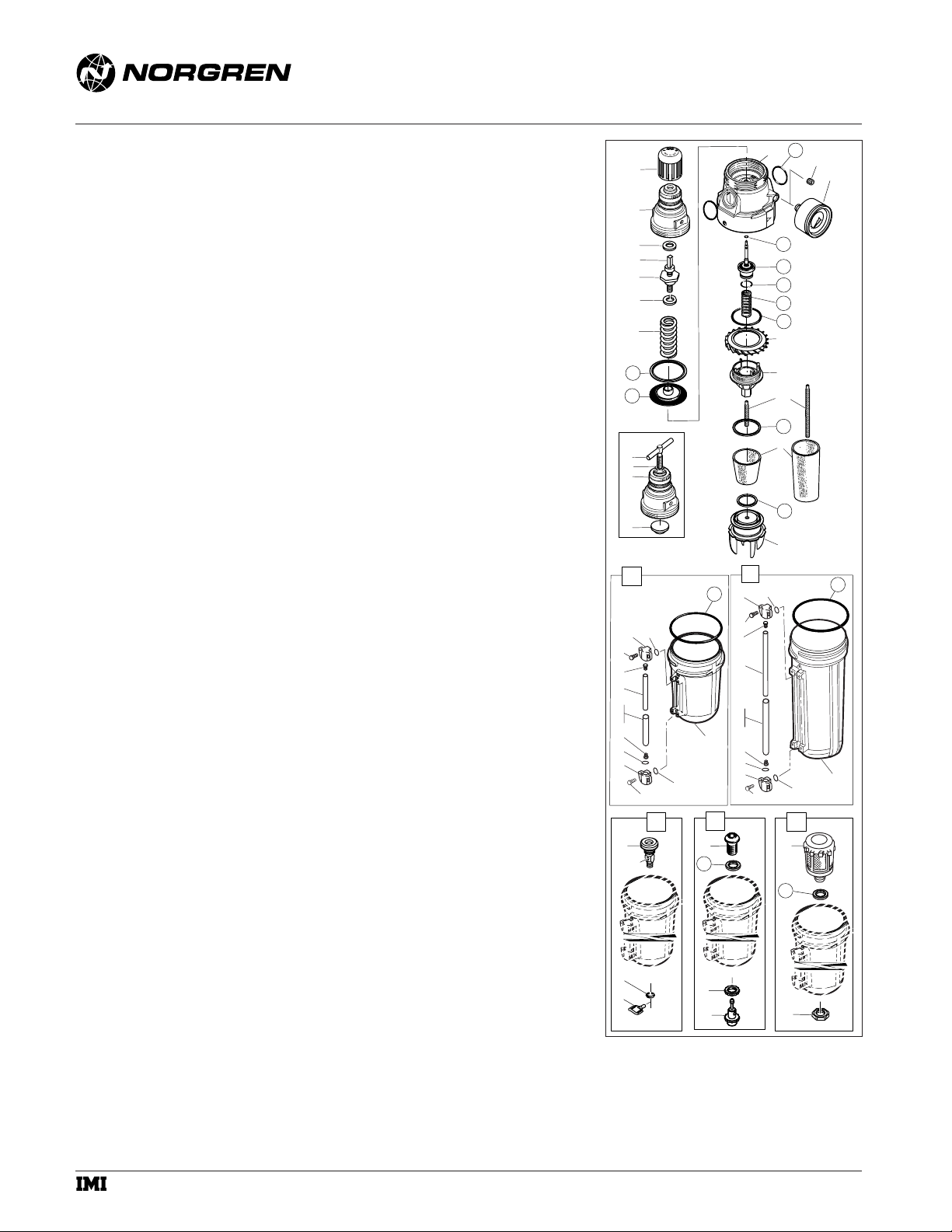
ASSEMBLY
1. Lubricate o-rings, the portion manual drain body (43) that
contacts the bowl, and the hole in the manual drain body
that accommodates the stem of drain valve (41) with oring grease.
2. Lubricate valve stem (62), adjusting screw threads and tip
(3, 7) and the recess of spring rest (10) with a light coat of
good quality o-ring grease.
3. Lubricate bonnet threads (2, 9) with a small amount of
anti-seize compound.
4. Assemble the unit as shown on the exploded view.
5. Assemble the liquid indicator parts (19 thru 26, 30 thru
37) to reservoir. Apply a 0.9 to 1.8 kg (2 to 4 pound)
clamping force to upper and lower sight glass brackets
(20, 31). Tighten screws (19, 30).
6. Torque Table
Item Torque in Nm (Inch-Pounds)
2, 9 (Bonnet) 62 to 68 (550 to 600)
16 (Pipe plug) 3,3 to 5,5 (29 to 49)
19, 30 (Screw) 1,8 to 2,3 (16 to 20)
45, 50 (Nut) 0,8 to 1,2 (7 to 10)
53 (Baffle) 1,1 to 1,4 (10 to 12)
WARNING
These products are intended for use in industrial
compressed air systems only. Do not use these products
where pressures and temperatures can exceed those listed
under Technical Data.
If outlet pressure in excess of the regulator pressure
setting could cause downstream equipment to rupture or
malfunction, install a pressure relief device downstream of
the regulator. The relief pressure and flow capacity of the
relief device must satisfy system requirements.
The accuracy of the indication of pressure gauges can
change, both during shipment (despite care in packaging)
and during the service life. If a pressure gauge is to be used
with these products and if inaccurate indications may be
hazardous to personnel or property, the gauge should be
calibrated before initial installation and at regular intervals
during use.
Before using these products with fluids other than air, for
non industrial applications, or for life-support systems
consult Norgren.
IM-260.300.02
(6/01)
© Norgren 2001
14
15
1
1
2
5
3
4
6
11
12
13
7
8
9
10
18
21
20
19
22
24
25
26
22
23
20
21
19
40
43
48
29
27
28
44
47
32
31
30
33
35
36
37
33
34
31
30
16
17
63
62
64
61
60
59
58
57
56
55
54
53
38
39
32
49
51
a subsidiary of IMI plc
52
42
41
45
46
50
 Loading...