

Norgren 10-028-037, 10-028-545, 10-028-046, 10-028-047, 10-028-048 Maintenance Manual
10-028
Installation & Maintenance
Instructions
ADJUSTMENT
1. Turn on system pressure.
2. Adjust lubricator drip rate under a steady flow condition.
Air flow should be at the rate the lubricator will be used.
Monitor drip rate thru sight feed dome (1).
3. Determine the air flow (scfm) thru the lubricator. Refer to
the shaded area in the Drip Rate Chart and determine the
drip rate corresponding to the air flow. Select an initial
drip rate toward the rich side of the shaded area for inlet
pressure less than 6,2 bar (90 psig), or toward the lean
side for inlet pressure more than 6,2 bar (90 psig). Turn
adjustment counterclockwise to increase and clockwise
to decrease the drip rate. Total travel of adjustment (1) is
320°.
4. Monitor the device being lubricated for a few days
following initial adjustment. Adjust the drip rate if the oil
delivery at the device appears either excessive or low.
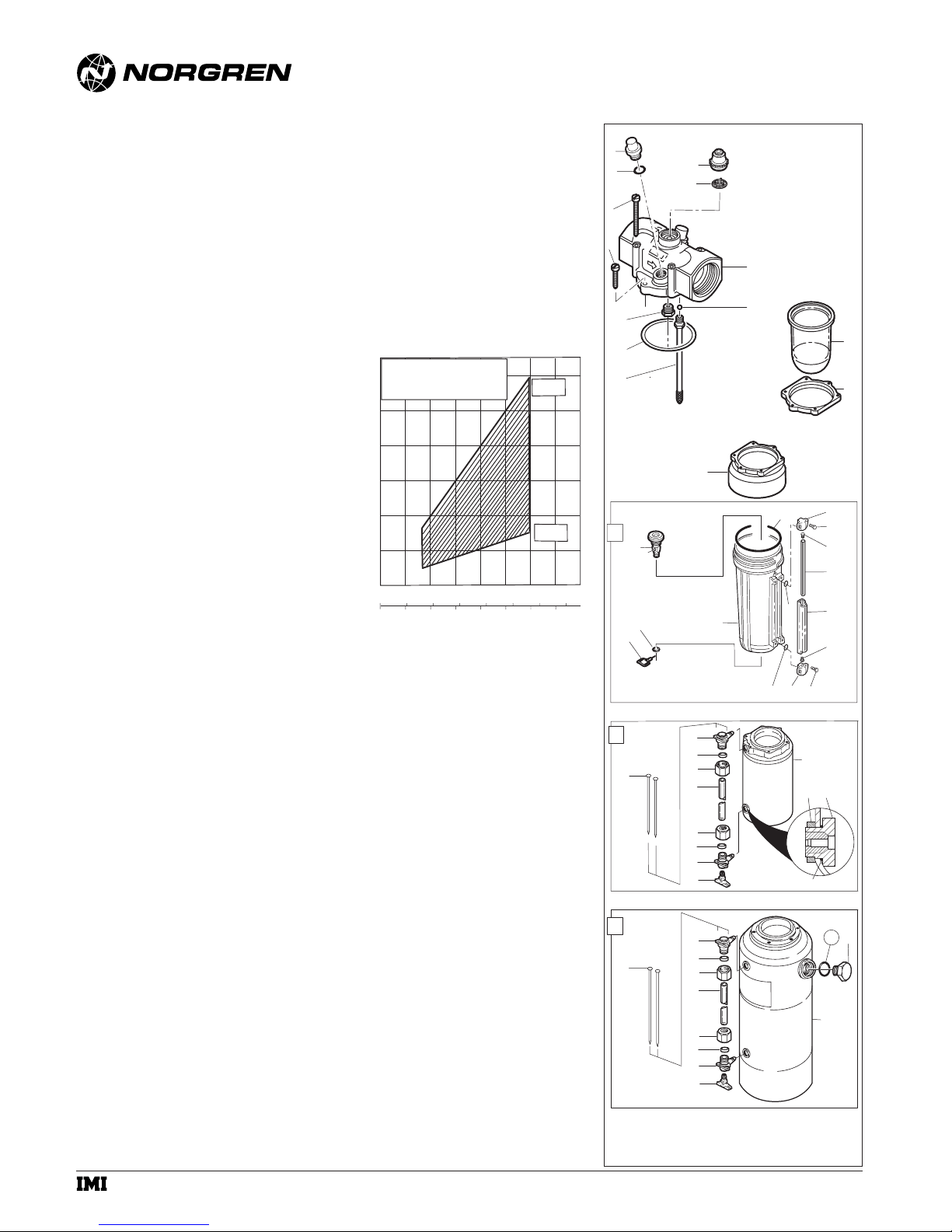
DISASSEMBLY
1. Shut off inlet pressure. Reduce pressure in inlet and
outlet lines to zero. Loosen fill plug. Lubricator may be
disassembled without removal from the air line.
2. Remove reservoir:
1-Quart Reservoir: Turn reservoir (40)
counterclockwise and remove from adapter (28).
All Other Reservoirs: Remove screws (6, 7) and
separate reservoir from body.
3. Disassemble in general accordance with the item
numbers on exploded view. Unscrew siphon tube
assembly (10), taking care not to lose check ball (11). Do
not remove siphon tube from fitting. Charge valve (9) is
not used with 2 and 5-gallon reservoirs. Do not remove
drain (30, 31, 32) unless replacement is necessary.
Remove and replace only if it malfunctions.
4. Disassembly of the reservoirs is not normally required.
CLEANING
1. Clean plastic reservoir and sight feed dome with warm
water only. Clean other parts using warm water and
soap.
2. Dry parts. Blow out internal passages in body with clean,
dry compressed air.
3. Inspect parts. Replace parts found to be damaged. If
plastic reservoir shows signs of cracking or cloudiness,
replace with a metal reservoir.
TECHNICAL DATA
Fluid: Compressed air
Maximum pressure:
Transparent bowl: 10 bar (150 psig)
Metal bowl: 17 bar (250 psig)
Operating temperature*:
Transparent bowl: -20° to 50°C (0° to 125°F)
Metal bowl: -20° to 80°C (0° to 175°F)
* Air supply must be dry enough to avoid ice formation at
temperatures below +2°C (+35°F).
Start point (minimum flow required for lubricator
operation) at 6,3 bar (90 psig) inlet pressure: 49 dm
3
/s
(103 scfm)
Typical flow at 6,3 bar (90 psig) inlet pressure and 0,35 bar
(5 psig) pressure drop: 268 dm
3
/s (568 scfm)
Reservoir sizes:
Model Nominal Capacity Working Capacity
10-028-037 0,25 liter (1/2 pt) 0,15 liter (5 fluid oz)
10-028-545 1 liter (1 qt) 0,56 liter (19 fluid oz)
10-028-046 2 liter (2 qt) 1,33 liter (45 fluid oz)
10-028-047 8 liter (2 gal) 3,34 liter (113 fluid oz)
10-028-048 20 liter (5 gal) 9,34 liter (316 fluid oz)
Materials:
Body: Aluminum
Reservoir:
Transparent 0,25 liter (1/2 pint): Polycarbonate
Metal:
1 liter (1 quart): Aluminum
2, 8 and 20 liter (2 quart, 2 and 5 gallon): Steel
(2 and 5 gallon reservoirs are rated to ASME
Pressure Vessel Code, Section VIII)
Metal bowl liquid level indicator lens: Pyrex
Sight-feed dome:
Standard: Polycarbonate
Optional: Pyrex and aluminum
Elastomers: Neoprene and nitrile
REPLACEMENT ITEMS
Liquid level lens kit
1-quart reservoir (33, 35, 36, 37, 38, 39) .......2273-22 *
2-quart reservoir (42, 43, 44, 45, 51) ................2273-04
2 and 5 gallon reservoirs (54, 55, 56, 57)..........2274-01
Pyrex sight feed dome.............................................5605-50
Quick fill cap..............................................18-011-008
Bowl guard for 1/2-pint reservoir ..............18-012-003
Wall mounting strap
2 gallon reservoir..................................18-001-056
5 gallon reservoir..................................18-001-039
* Current 1-quart reservoir models (Model 10-028-545)
use liquid level lens kit 2273-22. Early 1-quart reservoir
models (Model 10-028-045) are identical in appearance
to the 2-quart reservoir and use liquid level lens kit
2272-02.
INSTALLATION
1. Shut-off air pressure. Support weight of lubricator with 2
and 5 gallon reservoirs on shelf, floor, etc. Install
lubricator in air line -
● vertically (reservoir down),
● with air flow in direction of arrow on body,
● downstream of filters and regulators,
● upstream of cycling valves,
● as close as possible to the device being lubricated,
NOTE
Oil-Fog lubricators are generally installed no more than
5,2m (15 feet) from the device being lubricated. The
10-028 lubricator, however, will perform satisfactorily at
distances greater than 5,2m (15 feet) if installed at a
location sufficiently higher than the device being
lubricated, and the pipe network does not contain low
spots or complex bends.
2. Connect piping to proper ports using pipe thread sealant
on male threads only. Do not allow sealant to enter
interior of unit.
RECOMMENDED LUBRICANTS
Use a good quality, non-detergent, light, misting type oil for
compressed air tools. See Norgren publication
N/AL.8.900.935.
FILL RESERVOIR
Shut off inlet air pressure and reduce pressure in reservoir
to zero. Remove fill plug, add oil, and reinstall fill plug. Fill
to maximum fill line on transparent reservoir. Oil level must
always be visible in liquid level lens on metal reservoir. DO
NOT OVERFILL. Do not remove the fill plug on lubricators
with 2 and 5-gallon reservoirs when the reservoir is
pressurized, as oil will blow out the fill plug hole. The fill
plug on lubricators with smaller reservoirs may be removed
and the reservoir refilled when the reservoir is pressurized.
IM-450.410.01
(7/01)
Replaces NIP-364
© Norgren 2001
Oil-Fog Tool Lubricator
DRIP RATE CHART
PORT SIZE: 1-1/2"
120
INLET PRESSURE:
4 to 8 bar (60 to 100 psig)
100
80
60
40
20
DRIP RATE - DROPS PER MINUTE
0
0 100 200 300 dm3/s
0 200 400 600 scfm
AIR FLOW
RICH
LEAN
3
4
6
7
9
8
10
29
30
32
31
41
42
53
54
1
2
5
1/2 pint (0.25 liter)
11
1 quart (1 liter) Reservoir
28
39
40
34
35
2 quart (2 liter) Reservoir
46
44
43
45
43
44
47
48
2 and 5 gallon (8 and 20 liter) Reservoir
58
56
55
57
55
56
59
60
Reservoir
35
13
12
34
33
36
37
38
36
33
52
49
50
51
62
61
63
a subsidiary of IMI plc
10-028
Installation & Maintenance
Instructions
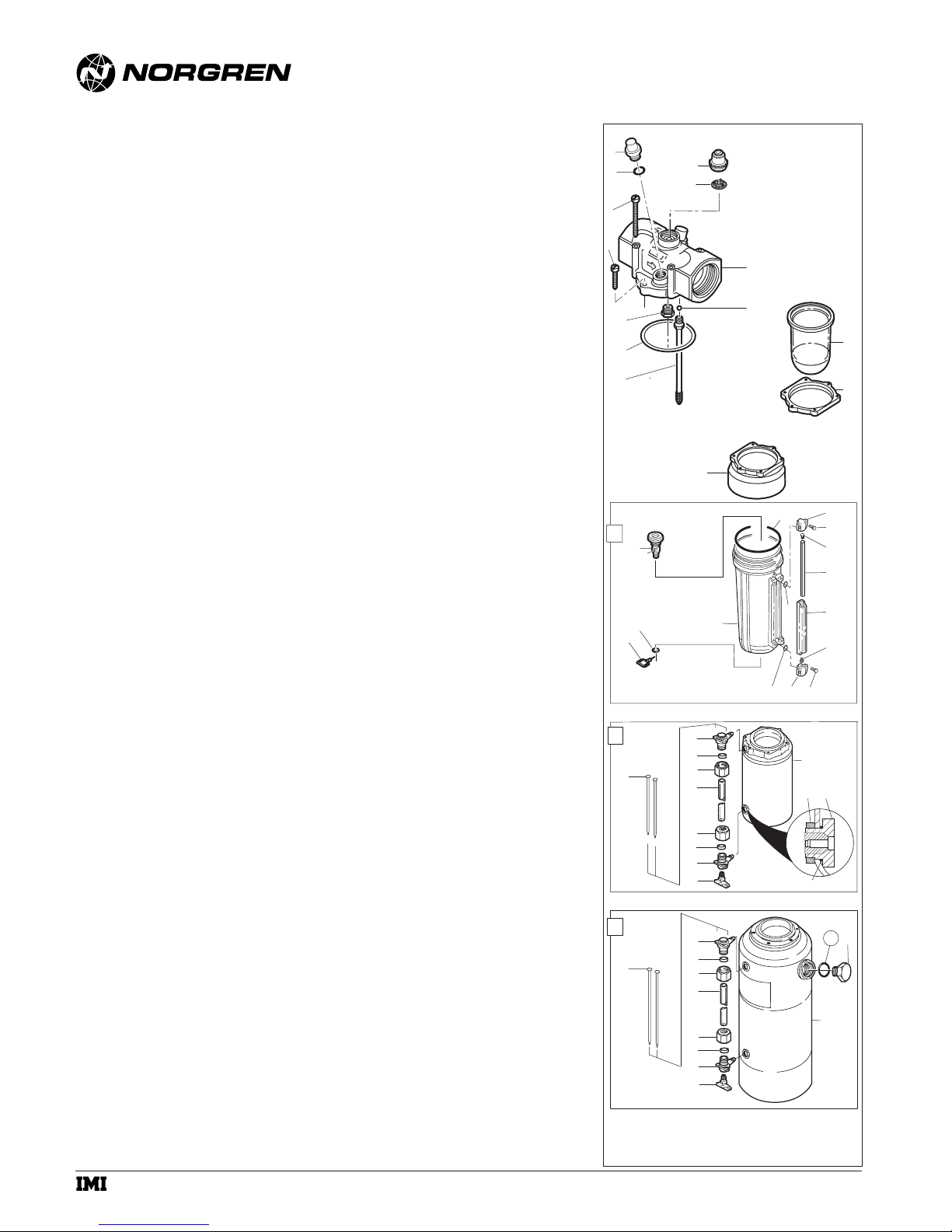
ASSEMBLY
1. Lubricate o-rings with o-ring grease.
2 If the 1/4 turn manual drain (30, 31, 32 ) was removed,
lubricate the portion of the drain body (30) that contacts
the bowl, and the hole in the manual drain body that
accommodates the stem of drain valve (31) with o-ring
grease. Press body (30) thru hole from inside of bowl.
Place retainer o-ring (32) over body (30) and position in
groove. Press drain valve (31) thru hole in body (30).
3. Assemble the liquid indicator parts (33 thru 38) to bowl.
Apply a 0,9 to 1,8 kg (2 to 4 pound) clamping force to
upper and lower brackets (34) to pull brackets together.
Tighten screws (33) to 0,9 to 1,1 N-m (8 to 10 inchpounds).
4. Assemble lubricator as shown on exploded view. Pay
particular attention to the following:
● Tighten sight feed dome (1) to 2,3 to 2,8 N-m (20 to
25 inch-pounds).
● Apply increasing torque to the six reservoir adapter
screws (6, 7) in a crisscross pattern. Apply final torque
of 2,26 to 3,39 N-m (20 to 30 inch-pounds).
● Turn bowl (40) into adapter (28) until arrowhead on
bowl is aligned with or to the right of slot in adapter.
WARNING
These products are intended for use in industrial
compressed air systems only. Do not use these products
where pressures and temperatures can exceed those listed
under Technical Data.
The polycarbonate sight feed dome and reservoir can be
damaged and possibly burst if exposed to such substances
as certain solvents, strong alkalies, compressor oils
containing ester-based additives or synthetic oils. Fumes of
these substances in contact with the polycarbonate sight
feed dome and reservoir, externally or internally, can also
result in damage. Clean with warm water only
Use pyrex sight feed dome and metal reservoir in
applications where the lubricator might be exposed to
substances that are incompatible with polycarbonate.
In lubrication applications some oil mist may escape
from the point of use to the surrounding atmosphere.
Users are referred to safety and health standards for
limiting oil mist contamination and utilization of protecting
equipment
Before using these products with fluids other than air,
for nonindustrial applications, or for life-support systems
consult Norgren.
IM-450.410.02
(7/01)
Replaces NIP-364
© Norgren 2001
Oil-Fog Tool Lubricator
3
4
6
7
9
8
10
29
30
32
31
1
2
5
1/2 pint (0.25 liter)
11
1 quart (1 liter) Reservoir
28
39
35
40
Reservoir
13
12
34
33
36
37
38
36
33
34
35
2 quart (2 liter) Reservoir
41
42
53
54
46
44
43
45
43
44
47
48
2 and 5 gallon (8 and 20 liter) Reservoir
58
56
55
57
55
56
59
60
52
49
51
50
62
61
63
a subsidiary of IMI plc
 Loading...