


Model No. NTEL7906.1
Serial No.
Serial
Number
Decal
QUESTIONS?
As a manufacturer, we are committed to providing complete customer satisfaction. If you have questions, or if parts are damaged or missing, PLEASE CONTACT OUR CUSTOMER SERVICE DEPARTMENT DIRECTLY.
CALL1-888TOLL-825-FREE:-2588 Mon.–Fri., 6 a.m.–6 p.m. MST Sat. 8 a.m.–5 p.m. MST
ON THE WEB: www.nordictrackservice.com
 CAUTION
Read all precautions and instructions in this manual before using this equipment. Keep this manual for future reference.
USER’S MANUAL


 Visit our website at
 www.nordictrack.com new products, prizes,
fitness tips, and much more!

TABLE OF CONTENTS
IMPORTANT PRECAUTIONS . . . . . . . . . . . . . . . . . . . . . . . . . . . . . . . . . . . . . . . . . . . . . . . . . . . . . . . . . . . . . . . .3 BEFORE YOU BEGIN . . . . . . . . . . . . . . . . . . . . . . . . . . . . . . . . . . . . . . . . . . . . . . . . . . . . . . . . . . . . . . . . . . . . . .4 ASSEMBLY . . . . . . . . . . . . . . . . . . . . . . . . . . . . . . . . . . . . . . . . . . . . . . . . . . . . . . . . . . . . . . . . . . . . . . . . . . . . . . .5 HOW TO USE THE ELLIPTICAL EXERCISER . . . . . . . . . . . . . . . . . . . . . . . . . . . . . . . . . . . . . . . . . . . . . . . . . .11 MAINTENANCE AND TROUBLESHOOTING . . . . . . . . . . . . . . . . . . . . . . . . . . . . . . . . . . . . . . . . . . . . . . . . . . .22 CONDITIONING GUIDELINES . . . . . . . . . . . . . . . . . . . . . . . . . . . . . . . . . . . . . . . . . . . . . . . . . . . . . . . . . . . . . . .23 PART LIST . . . . . . . . . . . . . . . . . . . . . . . . . . . . . . . . . . . . . . . . . . . . . . . . . . . . . . . . . . . . . . . . . . . . . . . . . . . . . .24 EXPLODED DRAWING . . . . . . . . . . . . . . . . . . . . . . . . . . . . . . . . . . . . . . . . . . . . . . . . . . . . . . . . . . . . . . . . . . . .26 ORDERING REPLACEMENT PARTS . . . . . . . . . . . . . . . . . . . . . . . . . . . . . . . . . . . . . . . . . . . . . . . . . .Back Cover LIMITED WARRANTY . . . . . . . . . . . . . . . . . . . . . . . . . . . . . . . . . . . . . . . . . . . . . . . . . . . . . . . . . . . . . .Back Cover
NordicTrack is a registered2trademark of ICON IP, Inc.

IMPORTANT PRECAUTIONS
WARNING: To reduce the risk of serious injury, read the following important precautions before using the elliptical exerciser.
1. Read all instructions in this manual and all warnings on the elliptical exerciser before using the elliptical exerciser. Use the elliptical exercise only as described in this manual.
2. It is the responsibility of the owner to ensure that all users of the elliptical exerciser are adequately informed of all precautions.
3. The elliptical exerciser is intended for home use only. Do not use the elliptical exerciser in a commercial, rental, or institutional setting.
4. Keep the elliptical exerciser indoors, away from moisture and dust. Place the elliptical exerciser on a level surface, with a mat beneath it to protect the floor or carpet. Make sure that there is enough clearance around the elliptical exerciser to mount, dismount, and use it.
5. Inspect and properly tighten all parts regularly. Replace any worn parts immediately.
6. Keep children under age 12 and pets away from the elliptical exerciser at all times.
7. The elliptical exerciser should not be used by persons weighing more than 325 lbs. (147 kg).
WARNING: Before beginning this or any exercise program, consult your physician. This is especially important for persons over the age of 35 or persons with pre-existing health problems. Read all instructions before using. ICON assumes no responsibility for personal injury or property damage sustained by or through the use of this product.
3
BEFORE YOU BEGIN
Thank you for purchasing the revolutionary NordicTrack® AUDIOSTRIDER 990 elliptical exerciser. The AUDIOSTRIDER 990 elliptical exerciser provides a wide array of features designed to make your workouts at home more effective and enjoyable—and when you’re not exercising, the unique elliptical exerciser can be folded out of the way.
For your benefit, read this manual carefully before you use the elliptical exerciser. If you have ques-
tions after reading this manual, please see the front cover of this manual. To help us assist you, note the product model number and serial number before contacting us. The model number is NTEL7906.1. The serial number can be found on a decal attached to the elliptical exerciser (see the front cover of this manual for the location of the decal).
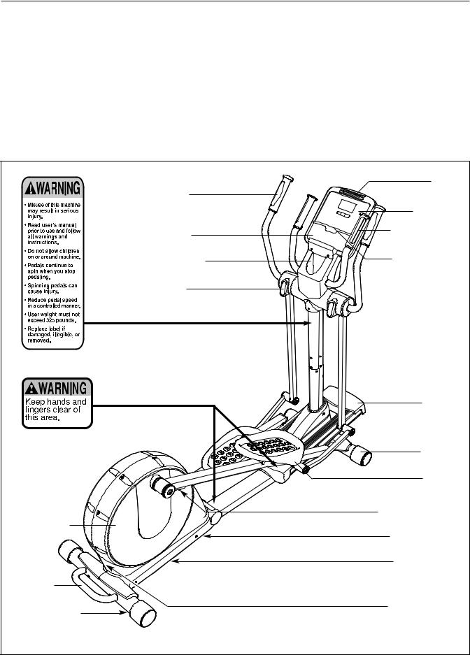
Before reading further, please familiarize yourself with the parts that are labeled in the drawing below.
Upper Body Arm |
Fan |
|
|
||
|
Console |
|
Stereo Speakers |
Pulse Sensor |
|
|
||
Water Bottle Holder* |
Stereo Cable |
|
Storage Magnet |
|
|
|
FRONT |
|
|
Ramp |
|
|
Wheel |
|
REAR |
Pedal |
|
|
||
Pedal Disc |
Pedal Arm Latch |
|
Leveling Foot |
||
|
||
|
Latch Button |
|
Handle |
RIGHT SIDE |
|
Leveling Foot |
Power Socket |
|
|
||
|
*No water bottle is included |
|
|
4 |
ASSEMBLY
Assembly requires two persons. Place all parts of the elliptical exerciser in a cleared area and remove the packing materials. Do not dispose of the packing materials until assembly is completed.
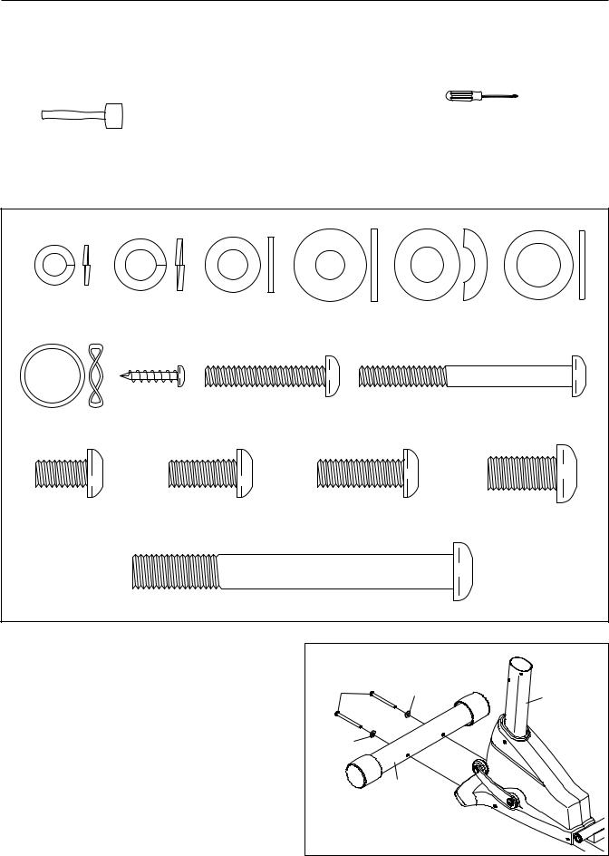
Assembly requires the included hex keys and your own phillips screwdriver |
and rubber |
|
mallet |
. |
|
As you assemble the elliptical exerciser, use the drawings below to identify small parts. The number in parentheses below each drawing is the key number of the part, from the PART LIST on pages 24 and 25. The number following the parentheses is the quantity needed for assembly. Note: Some small parts may have been preassembled. If a part is not in the parts bag, check to see if it has been preassembled.
M6 Split Washer |
|
M8 Split |
M8.5 x 16mm x |
M10 x 25mm |
M10 Curved |
Link Arm |
|
|
1.5mm Washer |
||||||
(102)–8 |
Washer (101)–4 |
(103)–6 |
Washer (87)–2 |
Washer (99)–4 |
Spacer (74)–4 |
||
Wave Washer |
|
M4 x 16mm |
M6 x 35mm |
|
M6 x 62mm |
||
Screw (116)–16 |
Screw (109)–4 |
|
Screw (108)–4 |
||||
(100)–2 |
|
|
|
|
|
|
|
M8 x 15mm Button |
M8 x 20mm Button |
M8 x 25mm Button |
M10 x 20mm Button |
||||
Screw (106)–10 |
Screw (107)–4 |
Screw (110)–2 |
|
Screw (111)–2 |
|||
|
|
|
M10 x 93mm Button Screw (82)–4 |
|
|
||
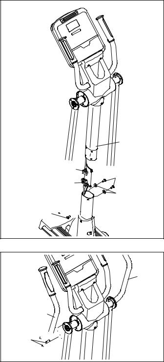
1. If there is a shipping bracket attached to the |
1 |
|
|
|
rear of the Folding Frame (not shown), remove |
|
|
||
|
|
|
||
the screw and the shipping bracket from the |
82 |
99 |
|
|
Folding Frame. Discard the screw and the ship- |
1 |
|||
|
||||
ping bracket. |
|
|
|
|
See HOW TO FOLD AND UNFOLD THE |
99 |
|
|
|
ELLIPTICAL EXERCISER on page 11 and |
|
|
||
|
|
|
||
unfold the elliptical exerciser. |
|
|
|
|
While another person lifts the front of the |
|
4 |
|
|
|
|
|
||
Frame (1), attach the Front Stabilizer (4) to the |
|
|
|
|
Frame with two M10 x 93mm Button Screws |
|
|
|
|
(82) and two M10 Curved Washers (99). |
|
|
|
|
|
5 |
|
|
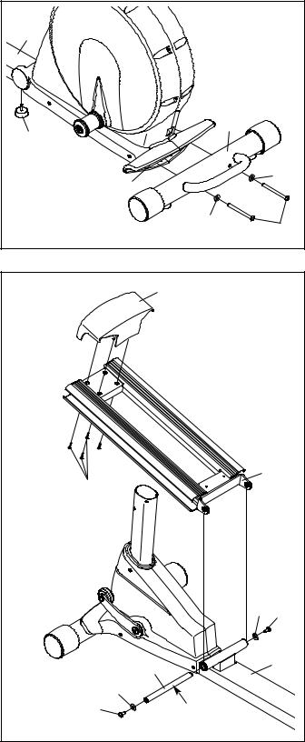
2.While another person lifts the Folding Frame (2), attach the Rear Stabilizer (3) to the Folding Frame with two M10 x 93mm Button Screws (82) and two M10 Curved Washers (99). Next, tighten the Center Foot (95) into the Frame (1).
3.Attach the Front Ramp Cover (6) to the Ramp (5) with four M4 x 16mm Screws (116).
Slide an M10 x 25mm Washer (87) onto an M10 x 20mm Button Screw (111). Tighten the Button Screw into one end of the Ramp
Axle (72). Apply a small amount of the included grease to the Ramp Axle.
Orient the Ramp (5) as shown. Align the lower end of the Ramp with the welded tube on the Frame (1). Insert the Ramp Axle (72) into the Ramp and the welded tube.
Slide an M10 x 25mm Washer (87) onto an M10 x 20mm Button Screw (111). Tighten the Button Screw into the open end of the Ramp Axle (72).
2 |
1 |
|
|
|
|
95 |
|
|
3 |
|
|
|
|
|
|
|
2 |
|
99 |
|
|
|
|
|
|
|
|
99 |
82 |
|
|
|
|
|
3 |
|
|
6 |
|
|
|
|
|
116 |
5 |
|
|
87 |
111 |
|
72 |
1 |
|
|
|
111 87 |
Grease |
|
6
4. Identify the Left Pedal (34) and the Left Pedal |
4 |
|
|
|
|
Arm (32), which are marked with stickers. |
|
34 |
|
|
|
|
|
|
|
||
Attach the Left Pedal (34) to the Left Pedal |
32 |
|
|
|
|
Arm (32) with two M6 x 62mm Screws (108), |
|
|
|
|
|
two M6 x 35mm Screws (109), and four M6 |
|
|
|
|
|
Split Washers (102). |
|
|
|
|
|
Attach the Right Pedal (not shown) to the |
|
|
|
|
|
Right Pedal Arm (not shown) in the same |
|
|
|
|
|
way. |
|
102 |
|
|
|
|
|
|
|
|
|
|
|
109 |
102 |
|
|
|
108 |
|
|
|
|
|
|
102109 |
|
|
|
|
|
|
|
|
|
5. Insert the Roller (38) on the Left Pedal Arm (32) |
5 |
|
|
|
|
and the Roller on the Right Pedal Arm (33) into |
|
|
116 |
|
|
|
|
|
|
||
the sides of the Ramp (5). |
|
|
|
|
7 |
|
|
|
|
|
|
Attach the Rear Ramp Cover (7) to the |
|
|
|
|
|
Ramp (5) with two M4 x 16mm Screws (116). |
|
|
33 |
|
|
|
|
|
|
|
|
See the inset drawing. Lift the Pedal Arm |
|
|
|
|
|
Latch (41) on the Left Pedal Arm (32) and set |
|
|
|
|
|
the end of the Left Pedal Arm on the left Crank |
|
|
|
|
|
Bushing Sleeve (54). Release the Pedal Arm |
|
|
|
|
|
Latch; make sure that the Left Pedal Arm is |
|
|
|
|
|
securely connected to the Crank Bushing |
|
|
|
|
|
Sleeve. |
|
|
5 |
|
38 |
Connect the Right Pedal Arm (33) to the |
|
|
|
||
|
|
|
|
|
|
right Crank Bushing Sleeve (not shown) in |
|
|
|
|
|
the same way. |
|
|
|
|
|
|
|
|
32 |
|
|
|
|
32 |
|
|
|
|
|
41 |
54 |
|
|
|
7 |
|
|
|
|
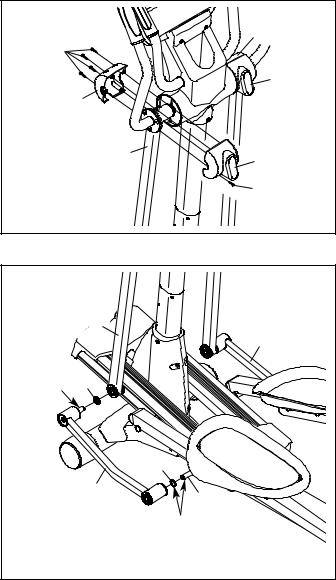
6.While another person holds the Upright (10) near the Frame (1), connect the Upper Wire Harness (65) to the Lower Wire Harness (64).
Carefully insert the Upright (10) into the
Frame (1); be careful not to damage the Wire Harnesses (64, 65). Attach the Upright with four M8 x 20mm Button Screws (107) and four M8 Split Washers (101).
6
Be careful not to damage the Wire Harnesses (64, 65) during this step
|
10 |
|
65 |
107 |
|
64 |
||
|
||
101 |
101 |
107


 1
1
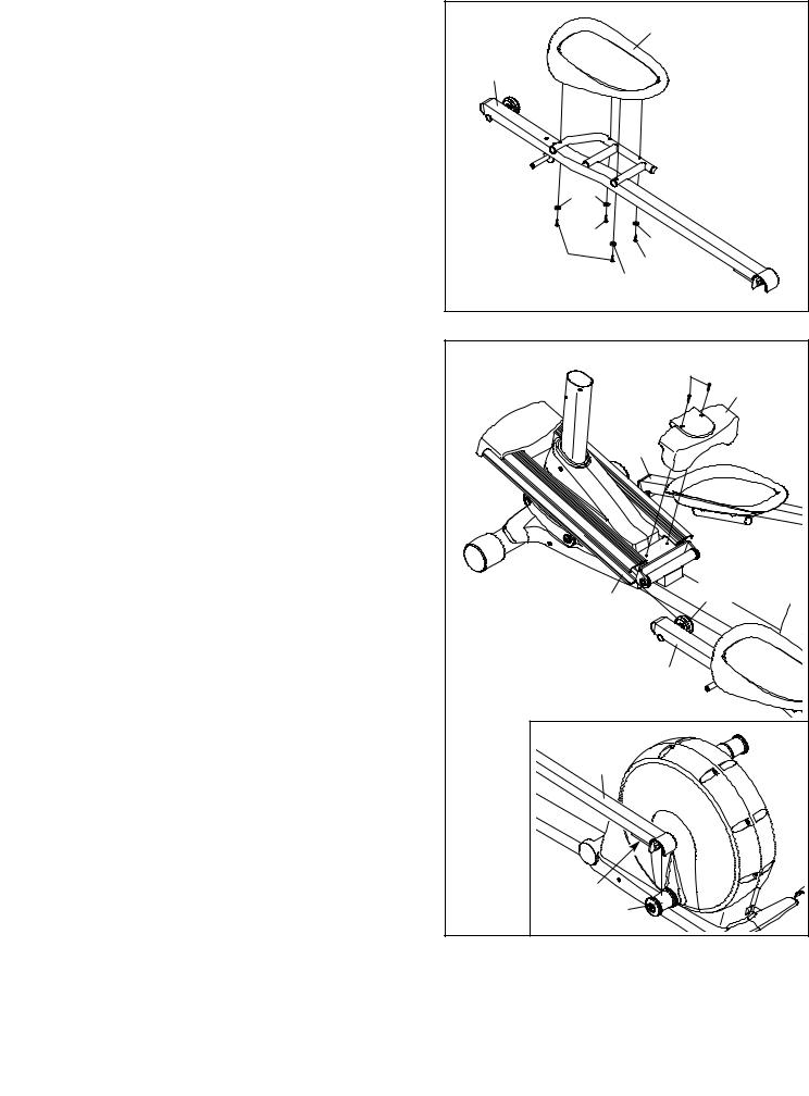
7. Attach the Left Upper Body Arm (22) to the left |
|
|
7 |
||
Upper Body Leg (24) with three M8 x 15mm |
||
|
||
Button Screws (106). |
|
|
|
Attach the Right Upper Body Arm (23) in the same way.
23
22
106


 24
24
8
8. Hold the Left Rear Upper Body Cover (26) and |
8 |
|
|
|
the Left Front Upper Body Cover (27) around |
|
|
29 |
|
|
|
|
||
the left Upper Body Leg (24). Attach the Upper |
|
116 |
|
|
|
|
|
||
Body Covers with five M4 x 16mm Screws (116). |
|
|
|
|
|
|
|
|
|
Attach the Right Rear Upper Body Cover (28) |
|
|
|
28 |
|
|
|
|
|
and the Right Front Upper Body Cover (29) |
|
|
27 |
|
in the same way. |
|
|
|
|
|
|
|
24 |
26 |
|
|
|
|
|
|
|
|
|
116 |
9.Apply a small amount of grease to the axle on the Left Link Arm (30), to the axle on the Left Pedal Arm (32), and to a Wave Washer (100).
Slide the Wave Washer (100) onto the axle on the Left Pedal Arm (32). Next, slide a Link Arm Spacer (74) onto the axle on the Left Link Arm (30).
Then, insert the axle on the Left Link Arm (30) into the left Upper Body Leg (24) while sliding the Left Link Arm onto the axle on the Left Pedal Arm (32).
Repeat this step with the Right Link Arm (31).
9 |
|
|
|
24 |
31 |
|
|
|
Grease |
74 |
|
|
|
100 |
|
30 |
32 |
|
|
|
|
|
Grease |
9
 Loading...