


 Loading...
Nokia Customer Care
Service Manual
RA-6 (Nokia E90 Communicator; L3&4)
Mobile Terminal
Part No: 9254834 (Issue 1)
COMPANY CONFIDENTIAL
Copyright © 2007 Nokia. All rights reserved.

|
|
|
RA-6 |
|
|
|
Amendment Record Sheet |
Amendment Record Sheet |
|
|
|
|
|
|
|
Amendment No |
Date |
Inserted By |
Comments |
Issue 1 |
05/2007 |
TSa |
|
|
|
|
|
Page ii |
COMPANY CONFIDENTIAL |
Issue 1 |
|
Copyright © 2007 Nokia. All rights reserved. |
|

RA-6
Copyright
Copyright
Copyright © 2007 Nokia. All rights reserved.
Reproduction, transfer, distribution or storage of part or all of the contents in this document in any form without the prior written permission of Nokia is prohibited.
Nokia, Nokia Connecting People, and Nokia X and Y are trademarks or registered trademarks of Nokia Corporation. Other product and company names mentioned herein may be trademarks or tradenames of their respective owners.
Nokia operates a policy of continuous development. Nokia reserves the right to make changes and improvements to any of the products described in this document without prior notice.
Under no circumstances shall Nokia be responsible for any loss of data or income or any special, incidental, consequential or indirect damages howsoever caused.
The contents of this document are provided "as is". Except as required by applicable law, no warranties of any kind, either express or implied, including, but not limited to, the implied warranties of merchantability and fitness for a particular purpose, are made in relation to the accuracy, reliability or contents of this document. Nokia reserves the right to revise this document or withdraw it at any time without prior notice.
The availability of particular products may vary by region.
IMPORTANT
This document is intended for use by qualified service personnel only.
Issue 1 |
COMPANY CONFIDENTIAL |
Page iii |
|
Copyright © 2007 Nokia. All rights reserved. |
|

RA-6
Warnings and cautions
Warnings and cautions
Warnings
•IF THE DEVICE CAN BE INSTALLED IN A VEHICLE, CARE MUST BE TAKEN ON INSTALLATION IN VEHICLES FITTED WITH ELECTRONIC ENGINE MANAGEMENT SYSTEMS AND ANTI-SKID BRAKING SYSTEMS. UNDER CERTAIN FAULT CONDITIONS, EMITTED RF ENERGY CAN AFFECT THEIR OPERATION. IF NECESSARY, CONSULT THE VEHICLE DEALER/ MANUFACTURER TO DETERMINE THE IMMUNITY OF VEHICLE ELECTRONIC SYSTEMS TO RF ENERGY.
•THE PRODUCT MUST NOT BE OPERATED IN AREAS LIKELY TO CONTAIN POTENTIALLY EXPLOSIVE ATMOSPHERES, FOR EXAMPLE, PETROL STATIONS (SERVICE STATIONS), BLASTING AREAS ETC.
•OPERATION OF ANY RADIO TRANSMITTING EQUIPMENT, INCLUDING CELLULAR TELEPHONES, MAY INTERFERE WITH THE FUNCTIONALITY OF INADEQUATELY PROTECTED MEDICAL DEVICES. CONSULT A PHYSICIAN OR THE MANUFACTURER OF THE MEDICAL DEVICE IF YOU HAVE ANY QUESTIONS. OTHER ELECTRONIC EQUIPMENT MAY ALSO BE SUBJECT TO INTERFERENCE.
•BEFORE MAKING ANY TEST CONNECTIONS, MAKE SURE YOU HAVE SWITCHED OFF ALL EQUIPMENT.
Cautions
•Servicing and alignment must be undertaken by qualified personnel only.
•Ensure all work is carried out at an anti-static workstation and that an anti-static wrist strap is worn.
•Ensure solder, wire, or foreign matter does not enter the telephone as damage may result.
•Use only approved components as specified in the parts list.
•Ensure all components, modules, screws and insulators are correctly re-fitted after servicing and alignment.
•Ensure all cables and wires are repositioned correctly.
•Never test a mobile phone WCDMA transmitter with full Tx power, if there is no possibility to perform the measurements in a good performance RF-shielded room. Even low power WCDMA transmitters may disturb nearby WCDMA networks and cause problems to 3G cellular phone communication in a wide area.
•During testing never activate the GSM or WCDMA transmitter without a proper antenna load, otherwise GSM or WCDMA PA may be damaged.
Page iv |
COMPANY CONFIDENTIAL |
Issue 1 |
|
Copyright © 2007 Nokia. All rights reserved. |
|

RA-6
ESD protection
ESD protection
Nokia requires that service points have sufficient ESD protection (against static electricity) when servicing the phone.
Any product of which the covers are removed must be handled with ESD protection. The SIM card can be replaced without ESD protection if the product is otherwise ready for use.
To replace the covers ESD protection must be applied.
All electronic parts of the product are susceptible to ESD. Resistors, too, can be damaged by static electricity discharge.
All ESD sensitive parts must be packed in metallized protective bags during shipping and handling outside any ESD Protected Area (EPA).
Every repair action involving opening the product or handling the product components must be done under ESD protection.
ESD protected spare part packages MUST NOT be opened/closed out of an ESD Protected Area.
For more information and local requirements about ESD protection and ESD Protected Area, contact your local Nokia After Market Services representative.
Issue 1 |
COMPANY CONFIDENTIAL |
Page v |
|
Copyright © 2007 Nokia. All rights reserved. |
|

RA-6
Care and maintenance
Care and maintenance
This product is of superior design and craftsmanship and should be treated with care. The suggestions below will help you to fulfil any warranty obligations and to enjoy this product for many years.
•Keep the phone and all its parts and accessories out of the reach of small children.
•Keep the phone dry. Precipitation, humidity and all types of liquids or moisture can contain minerals that will corrode electronic circuits.
•Do not use or store the phone in dusty, dirty areas. Its moving parts can be damaged.
•Do not store the phone in hot areas. High temperatures can shorten the life of electronic devices, damage batteries, and warp or melt certain plastics.
•Do not store the phone in cold areas. When it warms up (to its normal temperature), moisture can form inside, which may damage electronic circuit boards.
•Do not drop, knock or shake the phone. Rough handling can break internal circuit boards.
•Do not use harsh chemicals, cleaning solvents, or strong detergents to clean the phone.
•Do not paint the phone. Paint can clog the moving parts and prevent proper operation.
•Use only the supplied or an approved replacement antenna. Unauthorised antennas, modifications or attachments could damage the phone and may violate regulations governing radio devices.
All of the above suggestions apply equally to the product, battery, charger or any accessory.
Page vi |
COMPANY CONFIDENTIAL |
Issue 1 |
|
Copyright © 2007 Nokia. All rights reserved. |
|

RA-6
Company Policy
Company Policy
Our policy is of continuous development; details of all technical modifications will be included with service bulletins.
While every endeavour has been made to ensure the accuracy of this document, some errors may exist. If any errors are found by the reader, NOKIA MOBILE PHONES Business Group should be notified in writing/e- mail.
Please state:
•Title of the Document + Issue Number/Date of publication
•Latest Amendment Number (if applicable)
•Page(s) and/or Figure(s) in error
Please send to:
NOKIA CORPORATION
Nokia Mobile Phones Business Group
Nokia Customer Care
PO Box 86
FIN-24101 SALO
Finland
E-mail: Service.Manuals@nokia.com
Issue 1 |
COMPANY CONFIDENTIAL |
Page vii |
|
Copyright © 2007 Nokia. All rights reserved. |
|

RA-6
Battery information
Battery information
Note: A new battery's full performance is achieved only after two or three complete charge and discharge cycles!
The battery can be charged and discharged hundreds of times but it will eventually wear out. When the operating time (talk-time and standby time) is noticeably shorter than normal, it is time to buy a new battery.
Use only batteries approved by the phone manufacturer and recharge the battery only with the chargers approved by the manufacturer. Unplug the charger when not in use. Do not leave the battery connected to a charger for longer than a week, since overcharging may shorten its lifetime. If left unused a fully charged battery will discharge itself over time.
Temperature extremes can affect the ability of your battery to charge.
For good operation times with Ni-Cd/NiMh batteries, discharge the battery from time to time by leaving the product switched on until it turns itself off (or by using the battery discharge facility of any approved accessory available for the product). Do not attempt to discharge the battery by any other means.
Use the battery only for its intended purpose. Never use any charger or battery which is damaged.
Do not short-circuit the battery. Accidental short-circuiting can occur when a metallic object (coin, clip or pen) causes direct connection of the + and - terminals of the battery (metal strips on the battery) for example when you carry a spare battery in your pocket or purse. Short-circuiting the terminals may damage the battery or the connecting object.
Leaving the battery in hot or cold places, such as in a closed car in summer or winter conditions, will reduce the capacity and lifetime of the battery. Always try to keep the battery between 15°C and 25°C (59°F and 77° F). A phone with a hot or cold battery may temporarily not work, even when the battery is fully charged.
Batteries' performance is particularly limited in temperatures well below freezing. Do not dispose of batteries in a fire!
Dispose of batteries according to local regulations (e.g. recycling). Do not dispose as household waste.
Page viii |
COMPANY CONFIDENTIAL |
Issue 1 |
|
Copyright © 2007 Nokia. All rights reserved. |
|

RA-6
Nokia E90 Communicator; L3&4 Service Manual
Structure
Nokia E90 Communicator; L3&4 Service Manual Structure
1 General Information
2 Service Tools and Service Concepts
3 BB Troubleshooting and Tuning Guide
4 RF troubleshooting
5 Camera Module Troubleshooting
6 System Module Glossary
Issue 1 |
COMPANY CONFIDENTIAL |
Page ix |
|
Copyright © 2007 Nokia. All rights reserved. |
|

RA-6
Nokia E90 Communicator; L3&4 Service Manual
Structure
(This page left intentionally blank.)
Page x |
COMPANY CONFIDENTIAL |
Issue 1 |
|
Copyright © 2007 Nokia. All rights reserved. |
|
Nokia Customer Care
1 — General Information
Issue 1 |
COMPANY CONFIDENTIAL |
Page 1 –1 |
|
Copyright © 2007 Nokia. All rights reserved. |
|

RA-6
General Information
(This page left intentionally blank.)
Page 1 –2 |
COMPANY CONFIDENTIAL |
Issue 1 |
|
Copyright © 2007 Nokia. All rights reserved. |
|

RA-6
General Information
Table of Contents |
|
RA-6 product selection........................................................................................................................................... |
1–5 |
RA-6 product features and sales package............................................................................................................ |
1–5 |
Product and module list ........................................................................................................................................ |
1–7 |
Mobile enhancements............................................................................................................................................ |
1–8 |
Technical specifications......................................................................................................................................... |
1–9 |
Transceiver general specifications .................................................................................................................. |
1–9 |
Main RF characteristics for GSM850/900/1800/1900 and WCDMA1900/2100 phones ............................... |
1–9 |
Battery endurance.......................................................................................................................................... |
1–10 |
List of Tables |
|
Table 1 Audio .......................................................................................................................................................... |
1–8 |
Table 2 Car............................................................................................................................................................... |
1–8 |
Table 3 Data ............................................................................................................................................................ |
1–8 |
Table 4 Power ......................................................................................................................................................... |
1–8 |
Table 5 Carrying...................................................................................................................................................... |
1–9 |
List of Figures |
|
Figure 1 View of RA-6............................................................................................................................................. |
1–5 |
Issue 1 |
COMPANY CONFIDENTIAL |
Page 1 –3 |
|
Copyright © 2007 Nokia. All rights reserved. |
|

RA-6
General Information
(This page left intentionally blank.)
Page 1 –4 |
COMPANY CONFIDENTIAL |
Issue 1 |
|
Copyright © 2007 Nokia. All rights reserved. |
|
RA-6
General Information
RA-6 product selection
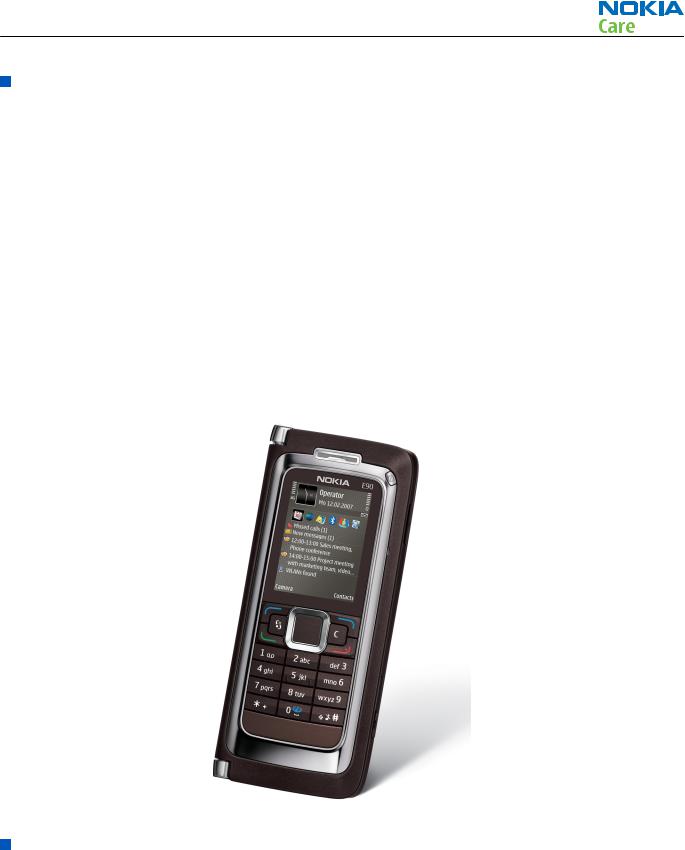
RA-6 is a WCDMA/GSM dual mode handportable phone supporting EGSM850/900/1800/1900 and WCDMA2100.
RA-6 is a 3GPP Release 5 terminal supporting WCDMA/HSDPA, EGPRS and GPRS data bearers. For WCDMA HSDPA the maximum bit rate is up to 3.6 Mbps for downlink and 384 kbps for uplink with simultaneous CS speech or CS video (max. 64 kbps).
For 2G and 2.5G networks the RA-6 is a Class A EGPRS DTM MSC 11 which means maximum download speed of up to 236.8 kbps simultaneously with speech or Class B EGPRS MSC 32 which means a in maximum download speed of up to 296kbit/s with EGPRS, and up to 107kbit/s with GPRS.
According to GSM standard 05.05 it responds to class 4 (max. 2W) in GSM 850 and EGSM 900 class 1 (1W) in DCS 1800 and class 1 in PCS 1900. RA-6 supports EGPRS (EDGE) class B as well as Bluetooth 2.0 EDR standard.
RA-6 supports two way video calls with two integrated cameras, one on the front and one on the back.
RA-6 is an MMS (Multimedia Messaging Service) enabled multimedia computer with a large 2.6’’ QVGA (240 x 320 pixels) TFT colour display and an integrated 5 Megapixel auto focus camera. The MMS implementation follows the OMA MMS standard release 1.2. The Browser is a highly advanced internet browser also capable of viewing operator domain XHTML Mobile Profile (MP) content.
RA-6 uses Symbian 9.2 operating system and supports also MIDP Java 2.0 & CLDC1.1, providing a good platform for compelling 3rd party applications.
Figure 1 View of RA-6
RA-6 product features and sales package
Communicator display and keypad
•Active matrix colour display (800 x 352), 16M colours
•5-way rocker key, 2 soft keys beside screen, send and end keys
•Full keyboard with backlight (separate key to activate light), Application shortcut keys, Series60 application key, profile key
Issue 1 |
COMPANY CONFIDENTIAL |
Page 1 –5 |
|
Copyright © 2007 Nokia. All rights reserved. |
|

RA-6
General Information
• Shortcuts to (chr+): Bluetooth, IR, help, volume control (call volume)
Cover display and ITU-T keypad
•Active matrix colour display (240 x 320), 16M colours •
•Full telephone keypad: Send and End keys, two separate Soft Keys, 5 way rocker, Power (including profile), Application key, C key, Nib on the “5” key number keys. The Zero key has the wireless internet symbol (long press activates web), silent profile activation in hash key
Hardware characteristics
•Communicator clamshell concept
•At least 128 MB free memory for user data and applications
•microSD (hot swap) memory card
•Integrated hands free speaker
•Internal Vibra
•Integrated GPS
•Integrated camera(s), 3Mpix with flash and autofocus, second camera QCIF for video calling
Connectivity
•Quad band GSM (850/900/1800/1900), WCDMA 2100
•GPRS/EGPRS (Class A, MSC 32)
•Dual mode transfer MSC11, SAIC rel v1
•HSDPA 3.6Mbit/s
•Mini USB type B interface with USB 2.0 full speed
•3.5mm stereo headphone plug and TV out support (PAL/NTSC)
•Bluetooth wireless technology 2.0
•Infrared (SIR)
•IrDA
•3GPP rel 5
Key features
UI and developer platform
•Series 60 Platform 3.1 Edition
•Symbian 9.2
•Java™ MIDP 2.0
Push email & PIM
•Intellisync Wireless Email
•Other emails :BlackBerry Connect, Mail for Exchange, Visto Mobile, Altexia Native S60 email & PIM
•POP3, IMAP4, SMTP, OMA DS 1.2
•Selectable email account
•Remote contact look-up
•Text-to-speech
•Instant messaging (Yahoo, AOL, OMA 1.2)
Page 1 –6 |
COMPANY CONFIDENTIAL |
Issue 1 |
|
Copyright © 2007 Nokia. All rights reserved. |
|

RA-6
General Information
•Calendar attachment support
•Meeting requests to calendar
•Calendar plug-in for 3rd party email solutions Seamless roaming
•Prioritized list of preferred access points •
•3rd party client (BirdStep) for seamless roaming Device Managemen
•Intellisync Device management
•OMA Device Management 1.1.2
•OMA Client Provisioning 1.1.2
•OTI firmware update
•Local connectivity with Nokia Suite
Security
•• Secure storage
•Device lock, also remote lock
•OMA DRM 2.0
•Wireless LAN security features
•Memory card lock
Other applications
•Web browser (x)HTML
•QuickOffice office tools
•Gate5 for location based services
•Catalogs application for add on application download
•Nokia Office Tools 2.0
•FM radio
Sales package
• |
Transceiver RA-6 |
|
|
• |
Charger (AC-4) |
|
|
• |
Battery (BP-4L) |
|
|
• Stereo headset (HS-47) |
|
|
|
• Connectivity cable (DKE-2) |
|
|
|
• Video out cable (CA-75U) |
|
|
|
• |
Memory card |
|
|
|
Product and module list |
|
|
|
|
|
|
|
|
|
|
|
|
|
|
|
Module name |
Type code |
Notes |
|
System/RF Module |
|
Main PWB with components |
|
|
|
|
|
UI Module |
|
Keyboard PWB with components. |
|
|
|
Part of the UI Frame Assy |
|
|
|
|
Issue 1 |
COMPANY CONFIDENTIAL |
Page 1 –7 |
|
Copyright © 2007 Nokia. All rights reserved. |
|

|
|
RA-6 |
|
|
General Information |
|
|
|
Module name |
Type code |
Notes |
Front Camera Module |
|
Camera module CIF |
|
|
|
Back Camera Module |
|
5MP camera with macro |
|
|
|
Display Module |
|
|
|
|
|
Engine Shield Assembly |
|
Part of slide assembly |
|
|
|
Slide Assembly |
|
Mechanical assembly |
|
|
|
Core SW Module |
|
|
|
|
|
Mobile enhancements
|
Table 1 Audio |
|
|
|
|
|
|
Enhancement |
|
|
Type |
Headsets |
|
HS-47 |
|
|
|
|
|
|
|
HS-42 |
|
|
|
|
|
Wireless headsets |
|
HS-25W |
|
|
|
|
|
Inductiove loopset |
|
TBD |
|
|
|
|
|
|
Table 2 Car |
|
|
|
|
|
|
Enhancement |
|
|
Type |
Mobile Holder and antenna coupler |
|
|
|
|
|
|
|
Mobile charger |
|
DC-4 |
|
|
|
|
|
Nokia A/V adapter for legacy car kits |
|
HF-6W |
|
|
|
|
|
Car kit |
|
N616 |
|
|
|
|
|
|
Table 3 Data |
|
|
|
|
|
|
Enhancement |
|
|
Type |
Connectivity adapter cable |
|
DKE-2 |
|
|
|
|
|
MicroSD card |
|
TBD |
|
|
|
|
|
|
Table 4 Power |
|
|
|
|
|
|
Enhancement |
|
|
Type |
Battery Li-ion |
|
BP-4L |
|
|
|
|
|
Travel charger |
|
AC-4 |
|
|
|
|
|
|
|
AC-5 |
|
|
|
|
|
Charger adapter |
|
CA-44 |
|
|
|
|
|
|
|
|
|
Page 1 –8 |
COMPANY CONFIDENTIAL |
Issue 1 |
|
Copyright © 2007 Nokia. All rights reserved.

RA-6
General Information
|
Table 5 Carrying |
|
|
|
|
Enhancement |
|
Type |
Wrist strap |
|
TBD |
|
|
|
Carrying case |
|
|
|
|
|
Technical specifications
Transceiver general specifications
Unit |
Dimensions (L x W x T) |
Weight (g) |
Volume (cm3) |
|
(mm) |
|
|
Transceiver with BP-4L |
132 x 57 x 20 mm |
210 |
140 |
Li-ion battery back |
|
|
|
|
|
|
|
Main RF characteristics for GSM850/900/1800/1900 and WCDMA1900/2100 phones
Parameter |
Unit |
Cellular system |
GSM850, EGSM900, GSM1800/1900, WCDMA1900 or |
|
WCDMA2100 |
|
|
Rx frequency band |
GSM850: 869 - 894MHz |
|
|
|
EGSM900: 925 - 960 MHz |
|
|
|
GSM1800: 1805 - 1880 MHz |
|
|
|
GSM1900: 1930 - 1990 MHz |
|
|
|
WCDMA1900: 1930-1990MHz |
|
|
|
WCDMA2100: 2110 - 2170 MHz |
|
|
Tx frequency band |
GSM850: 824 - 849MHz |
|
|
|
EGSM900: 880 - 915 MHz |
|
|
|
GSM1800: 1710 - 1785 MHz |
|
|
|
GSM1900: 1850 - 1910 MHz |
|
|
|
WCDMA1900: 1850-1910MHz |
|
|
|
WCDMA2100: 1920 - 1980 MHz |
|
|
Output power |
GSM850: +5 ...+33dBm/3.2mW ... 2W |
|
|
|
GSM900: +5 … +33dBm/3.2mW … 2W |
|
|
|
GSM1800: +0 … +30dBm/1.0mW … 1W |
|
|
|
GSM1900: +0 … +30dBm/1.0mW … 1W |
|
|
|
WCDMA -50 … 24 dBm |
|
|
Issue 1 |
COMPANY CONFIDENTIAL |
Page 1 –9 |
|
Copyright © 2007 Nokia. All rights reserved. |
|

RA-6
General Information
Parameter |
Unit |
Number of RF channels |
GSM850: 124 |
|
|
|
GSM900: 174 |
|
|
|
GSM1800: 374 |
|
|
|
GSM1900: 299 |
|
|
Channel spacing |
200 kHz |
|
|
Number of Tx power levels |
GSM850: 15 |
|
|
|
GSM900: 15 |
|
|
|
GSM1800: 16 |
|
|
|
GSM1900: 16 |
|
|
Battery endurance
Battery |
Capacity (mAh) |
Talk time |
Stand-by |
BP-4L |
1500 |
5 hrs |
up to 14 days |
|
|
|
|
Charging times
AC-4
(TBD)
Page 1 –10 |
COMPANY CONFIDENTIAL |
Issue 1 |
|
Copyright © 2007 Nokia. All rights reserved. |
|
Nokia Customer Care
2 — Service Tools and Service
Concepts
Issue 1 |
COMPANY CONFIDENTIAL |
Page 2 –1 |
|
Copyright © 2007 Nokia. All rights reserved. |
|

RA-6
Service Tools and Service Concepts
(This page left intentionally blank.)
Page 2 –2 |
COMPANY CONFIDENTIAL |
Issue 1 |
|
Copyright © 2007 Nokia. All rights reserved. |
|

RA-6
Service Tools and Service Concepts
Table of Contents |
|
Service tools............................................................................................................................................................ |
2–5 |
CA-31D ................................................................................................................................................................ |
2–5 |
CA-35S................................................................................................................................................................. |
2–5 |
CU-4..................................................................................................................................................................... |
2–6 |
DKE-2................................................................................................................................................................... |
2–7 |
FLS-5 ................................................................................................................................................................... |
2–7 |
FPS-10................................................................................................................................................................. |
2–7 |
FS-49 ................................................................................................................................................................... |
2–8 |
MJ-115................................................................................................................................................................. |
2–8 |
PCS-1 ................................................................................................................................................................... |
2–8 |
PKD-1 .................................................................................................................................................................. |
2–9 |
RJ-150 ................................................................................................................................................................. |
2–9 |
SA-125 ................................................................................................................................................................ |
2–9 |
SA-131 ................................................................................................................................................................ |
2–9 |
SB-6..................................................................................................................................................................... |
2–9 |
SB-7.................................................................................................................................................................. |
2–10 |
SRT-6................................................................................................................................................................ |
2–10 |
SS-46 ................................................................................................................................................................ |
2–10 |
SS-62 ................................................................................................................................................................ |
2–10 |
SS-81 ................................................................................................................................................................ |
2–11 |
SS-93 ................................................................................................................................................................ |
2–11 |
SX-4.................................................................................................................................................................. |
2–11 |
XCS-4 ................................................................................................................................................................ |
2–11 |
XRS-6................................................................................................................................................................ |
2–11 |
Service concepts .................................................................................................................................................. |
2–12 |
POS (Point of Sale) flash concept .................................................................................................................. |
2–12 |
POS (Point of Sale) flash concept .................................................................................................................. |
2–13 |
Module jig service concept ............................................................................................................................ |
2–14 |
Service concept for RF testing and RF/BB tuning ........................................................................................ |
2–15 |
Flash concept with FPS-10............................................................................................................................. |
2–16 |
RF testing concept with RF coupler .............................................................................................................. |
2–17 |
CU-4 flash concept with FPS-10..................................................................................................................... |
2–18 |
List of Figures |
|
Figure 2 POS flash concept ................................................................................................................................. |
2–12 |
Figure 3 POS flash concept ................................................................................................................................. |
2–13 |
Figure 4 Module jig service concept .................................................................................................................. |
2–14 |
Figure 5 Service concept for RF testing and RF/BB tuning .............................................................................. |
2–15 |
Figure 6 Basic flash concept with FPS-10.......................................................................................................... |
2–16 |
Figure 7 RF testing concept with RF coupler .................................................................................................... |
2–17 |
Figure 8 CU-4 flash concept with FPS-10........................................................................................................... |
2–18 |
Issue 1 |
COMPANY CONFIDENTIAL |
Page 2 –3 |
|
Copyright © 2007 Nokia. All rights reserved. |
|

RA-6
Service Tools and Service Concepts
(This page left intentionally blank.)
Page 2 –4 |
COMPANY CONFIDENTIAL |
Issue 1 |
|
Copyright © 2007 Nokia. All rights reserved. |
|
RA-6
Service Tools and Service Concepts
Service tools
The table below gives a short overview of service tools that can be used for testing, error analysis and repair of product RA-6, refer to various concepts.
|
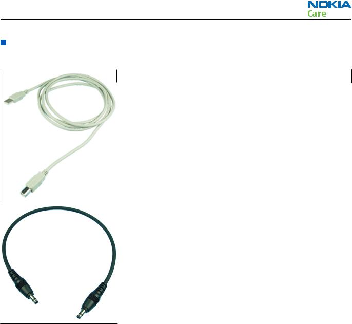
CA-31D |
USB cable |
|
|
|
|
|
The CA-31D USB cable is used to connect FPS-10 or FPS-11 to a PC. It is included in the FPS-10 and FPS-11 sales packages.
|
CA-35S |
Power cable |
|
|
|
|
|
CA-35S is a power cable for connecting, for example, the FPS-10 flash prommer to the Point-Of-Sales (POS) flash adapter.
Issue 1 |
COMPANY CONFIDENTIAL |
Page 2 –5 |
|
Copyright © 2007 Nokia. All rights reserved. |
|
RA-6
Service Tools and Service Concepts
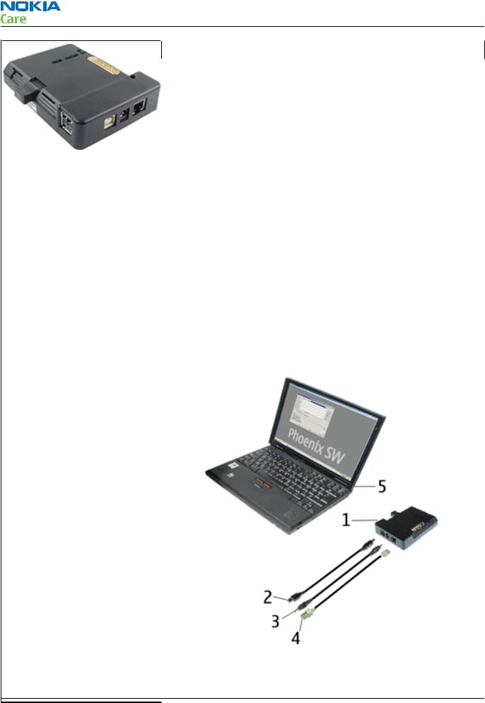
CU-4 |
Control unit |
|
|
|
|
CU-4 is a general service tool used with a module jig and/or a flash adapter. It requires an external 12 V power supply.
The unit has the following features:
•software controlled via USB
•EM calibration function
•Forwards FBUS/Flashbus traffic to/from terminal
•Forwards USB traffic to/from terminal
•software controlled BSI values
•regulated VBATT voltage
•2 x USB2.0 connector (Hub)
•FBUS and USB connections supported
When using CU-4, note the special order of connecting cables and other service equipment:
Instructions
1Connect a service tool (jig, flash adapter) to CU-4.
2Connect CU-4 to your PC with a USB cable.
3Connect supply voltage (12 V)
4Connect an FBUS cable (if necessary).
5Start Phoenix service software.
Note: Phoenix enables CU-4 regulators via USB when it is started.
Reconnecting the power supply requires a Phoenix restart.
Page 2 –6 COMPANY CONFIDENTIAL Issue 1 Copyright © 2007 Nokia. All rights reserved.

RA-6
Service Tools and Service Concepts
|
DKE-2 |
Mini-USB cable |
|
|
|
|
|
USB to mini-USB connector cable.
|
FLS-5 |
Flash device |
|
|
|
|
|
FLS-5 is a dongle and flash device incorporated into one package, developed specifically for POS use.
|
FPS-10 |
Flash prommer |
|
|
|
|
|
FPS-10 interfaces with:
•PC
•Control unit
•Flash adapter
•Smart card
FPS-10 flash prommer features:
•Flash functionality for BB5 and DCT-4 terminals
•Smart Card reader for SX-2 or SX-4
•USB traffic forwarding
•USB to FBUS/Flashbus conversion
•LAN to FBUS/Flashbus and USB conversion
•Vusb output switchable by PC command
FPS-10 sales package includes:
•FPS-10 prommer
•Power Supply with 5 country specific cords
•USB cable
Issue 1 |
COMPANY CONFIDENTIAL |
Page 2 –7 |
|
Copyright © 2007 Nokia. All rights reserved. |
|

RA-6
Service Tools and Service Concepts
FS-49 |
Flash adapter |
|
|
|
|
Flash adapter FS-49 is used for phone testing and flashing. FS-49 is used with the generic flash adapter base SS-60/62 and control unit CU-4 or interface adapter SS-46.
When flashing or system testing the phone, the adapter is attached to replace the phone own battery.
All functions (as well as the calibration voltages, current and the protections for over voltages, over current and voltage polarity), are performed by CU-4.
Flash adapter FS-49 main features:
•VBATT supply interface
•USB / FBUS multiplexed interface to the phone
|
MJ-115 |
Module jig |
|
|
|
|
|
MJ-115 can be used for flashing as well as for RF, battery and system testing.
MJ-115 main functions:
•CU-4 interface adapter to phone
•FBUS interface to phone
•UI Interface to phone
•WCDMA and GSM RF-interface
All functions are performed in CU-4 e.g. calibration voltages and currents both all protections (over current, over voltage and voltage polarity).
MJ-115 contains following interfaces to phone:
•VBATT interface
•UI interface containing Display connector
•WCDMA and GSM RF interfaces
•Bluetooth RF interface
•Earpiece interface
•IHF speaker interface
•Microphone interface
|
PCS-1 |
Power cable |
|
|
|
|
|
The PCS-1 power cable (DC) is used with a docking station, a module jig or a control unit to supply a controlled voltage.
Page 2 –8 |
COMPANY CONFIDENTIAL |
Issue 1 |
|
Copyright © 2007 Nokia. All rights reserved. |
|
RA-6
Service Tools and Service Concepts
|
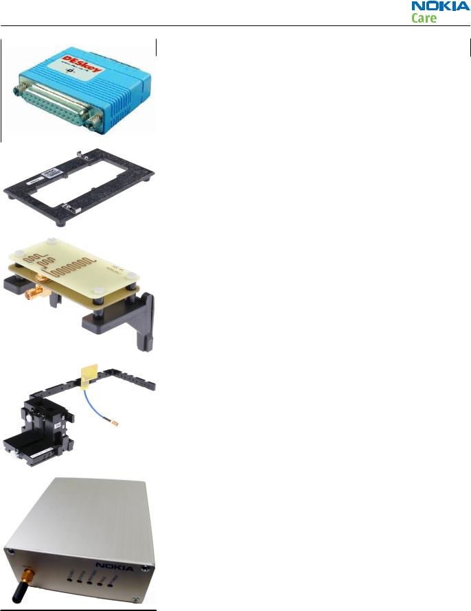
PKD-1 |
SW security device |
|
|
|
|
|
SW security device is a piece of hardware enabling the use of the service software when connected to the parallel (LPT) port of the PC.
Without the device, it is not possible to use the service software.
Printer or any such device can be connected to the PC through the device if needed.
|
RJ-150 |
Soldering jig |
|
|
|
|
|
RJ-150 is a soldering jig used for soldering and as a rework jig for the engine module.
|
SA-125 |
RF coupler |
|
|
|
|
|
SA-125 is an RF coupler for WCDMA and GSM RF testing. It is used together with the product-specific flash adapter.
|
SA-131 |
RF coupler |
|
|
|
|
|
SA-131 is a generic device for GPS testing.
|
SB-6 |
Bluetooth tester |
|
|
|
|
|
The SB-6 test box is a generic device to perform Bluetooth bit error rate testing and doing cordless FBUS connection via Bluetooth.
Issue 1 |
COMPANY CONFIDENTIAL |
Page 2 –9 |
|
Copyright © 2007 Nokia. All rights reserved. |
|
|
|
|
RA-6 |
|
|
Service Tools and Service Concepts |
|
|
|
|
|
|
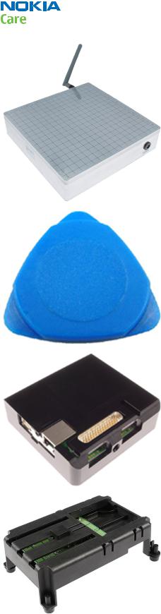
SB-7 |
WLAN test box |
|
|
|
|
|
|
WLAN test requires defined position for the device. |
||
|
|
|
|
|
SRT-6 |
Opening tool |
|
|
|
|
|
|
SRT-6 is used to open phone covers. |
||
|
|
|
|
|
SS-46 |
Interface adapter |
|
|
|
|
|
|
SS-46 acts as an interface adapter between the flash adapter and |
||
|
FPS-10. |
|
|
|
|
|
|
|
SS-62 |
Generic flash adapter |
|
|
|
base for BB5 |
|
|
|
|
|
|
• generic base for flash adapters and couplers |
||
|
• SS-62 equipped with a clip interlock system |
||
|
• provides standardised interface towards Control Unit |
||
|
• provides RF connection using galvanic connector or coupler |
||
|
• multiplexing between USB and FBUS media, controlled by VUSB |
||
|
|
|
|
Page 2 –10 |
COMPANY CONFIDENTIAL |
Issue 1 |
|
Copyright © 2007 Nokia. All rights reserved. |
|
Loading...