


Owner’s Manual
MOVANO
Operation, Safety and Maintenance
O N VAO M
VAUXHALL Movano
Operation, Safety, Maintenance
Data specific to your vehicle
Please enter your vehicle’s data here to keep it easily accessible.
This information is available under the section "Technical data" as well as on the identification plate and in the Service Booklet.
Fuel
Designation
Engine oil
Grade
Viscosity
Tyre inflation pressure
|
Tyre size |
|
with full load |
|
|
|
|
|
|
Summer tyres |
|
Front |
|
Rear |
|
|
|
|
|
|
|
|
|
|
Winter tyres |
|
Front |
|
Rear |
|
|
|
|
|
Weights
Permissible Gross Vehicle Weight
– |
EC kerbweight |
= |
Loading |

Your Movano
is an intelligent combination of forwardlooking technology, impressive safety, environmental friendliness and economy.
It now lies with you to drive your vehicle safely and ensure that it performs perfectly. This Owner’s Manual provides you with all the necessary information to that end.
Make sure your passengers are aware of the possible risk of accident and injury
which may result from improper use of the vehicle.
You must always comply with the specific laws of the country that you are travelling through. These laws may differ from the information in this Owner’s Manual.
When this Manual refers to a workshop visit, we recommend your Vauxhall Authorised Repairer.
All Vauxhall Authorised Repairers provide first-class service at reasonable prices.
You will receive quick, reliable and individual service.
Experienced mechanics, trained by Vauxhall, work according to specific Vauxhall instructions.
The Owner’s Manual should always be kept in the vehicle: Ready to hand in the glove compartment.
Make use of the Owner’s Manual:
z The "In Brief" section will give you an initial overview.
z The table of contents at the beginning of the owner’s manual and within the individual chapters will show you where everything is.
z Its index will help you find what you want.
z It will familiarise you with the sophisticated technology.
z It will increase your pleasure in your vehicle.
z It will help you to handle your vehicle expertly.
The Owner’s Manual is designed to be clearly laid-out and easily understood.
This symbol signifies:
6 Continue reading on next page.
3 Items marked with an asterisk are not fitted to all vehicles (model variants, engine options, models specific to one country, optional equipment, Genuine Vauxhall Parts and Accessories).
9Warning
Text marked 9 Warning provides information on risk of accident or injury. Disregard of the instructions may lead to injuries or endanger life.
Inform your passengers accordingly.
Yellow arrows in the illustrations serve as points of reference or indicate some action to be performed.
Black arrows in the illustrations indicate a reaction or a second action to be performed.
Directional data, e.g. left or right, or front or back, in the descriptions always relate to the direction of travel.
Thank you for choosing a Vauxhall. We wish you many hours of pleasurable driving
Your Vauxhall Team

Contents
Commitment to customer satisfaction:
Our aim: to keep you happy with your vehicle. All Vauxhall Authorised Repairers offer first class service at competitive prices. Experienced, factory-trained technicians work according to factory instructions. Your Authorised Repairer can supply you with GENUINE VAUXHALLAPPROVED PARTS, which have undergone stringent quality and precision checks, and of course useful and attractive VAUXHALL-APPROVED ACCESSORIES.
Our name is your guarantee!
For details of the
Vauxhall Authorised Repairer Network please ring this number; 0845 090 2044
In brief ......................................................... |
2 |
Instruments .............................................. |
18 |
Keys, doors, bonnet ................................ |
29 |
Seats, interior........................................... |
40 |
Safety systems......................................... |
48 |
Lighting .................................................... |
62 |
Windows................................................... |
67 |
Heating, ventilation ................................ |
71 |
Tecshift..................................................... |
80 |
Driving hints............................................. |
86 |
Save fuel, protect the environment ....... |
88 |
Fuel consumption, fuel, refuelling.......... |
90 |
Catalytic converter, exhaust emissions . 92 |
|
Drive Control Systems ............................. |
96 |
Chassis systems ....................................... |
98 |
Brakes..................................................... |
103 |
Wheels, tyres.......................................... |
107 |
Roof rack, caravan and trailer towing |
112 |
Self-help ................................................. |
115 |
If you have a problem .......................... |
134 |
Service plan, maintenance ................... |
136 |
Vehicle care ........................................... |
147 |
Technical data ...................................... |
152 |
Index....................................................... |
168 |
2 In brief
In brief
Key numbers, Code numbers
Remove key number from key.
The key number is given in the vehicle documents and in the Car Pass 3.
Electronic immobiliser, radio 3: The code numbers are given in the
Car Pass and Radio Pass respectively.
Do not keep the Car Pass and Radio Pass in the vehicle.
6 Further information - see pages 29, 30.
Unlocking the vehicle: Direct remote control unit towards vehicle,
press button c, pull door handle
To unlock mechanically:
Insert key and turn in driver’s door lock and pull door handle.
To lock doors from inside:
Press central locking button located on the overhead console.
6 Door locks - see page 29, electronic immobiliser - see page 30, remote control - see page 31, central locking system - see page 33,
Vauxhall alarm system 3 - see page 35.
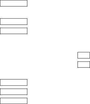
Seat adjustment:
Pull handle, slide seat, release handle,
allow seat to audibly latch into position
Never adjust the driver's seat whilst driving. It could move in an uncontrolled manner when the handle has been pulled.
In brief |
3 |
|
|
|
|
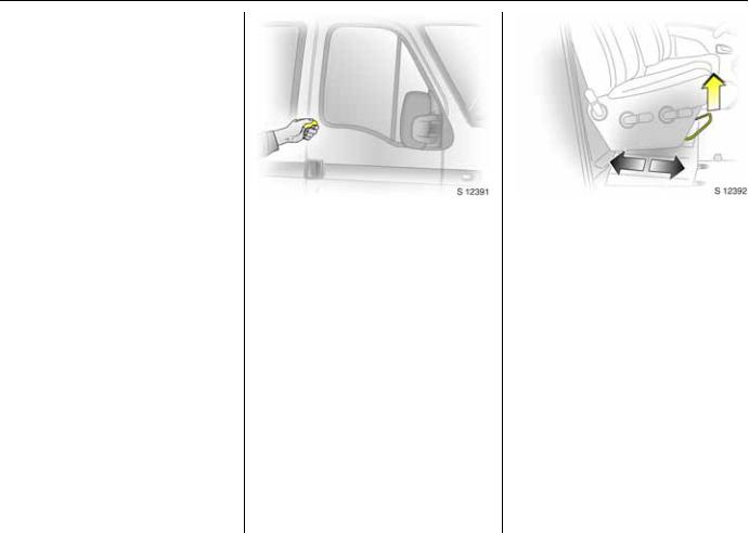
Adjusting the front seat backrest: Push release lever
Move seat backrest to suit seating position, it will lock in position when the lever is released.
9Warning
Important: Do not sit nearer than 10 inches (25 cm) from the steering
wheel, to permit safe airbag deployment.
Adjusting the front seat height: Pull up lever, adjust seat, release lever,
lock seat into position
Front lever: Adjusts front of seat Rear lever: Adjusts rear of seat
Driver’s seat armrest
Armrest can be lowered from upright position for added comfort. Return armrest to upright position when not required.
4 In brief
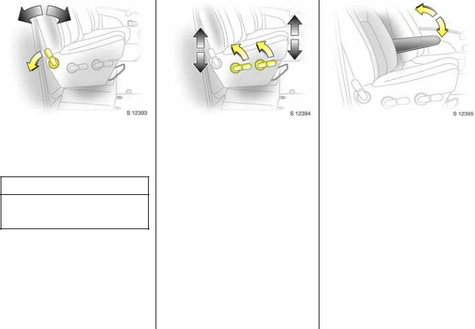
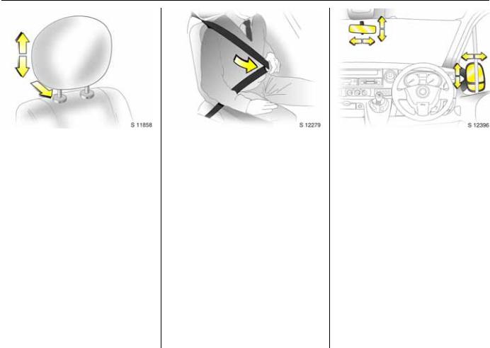
Adjusting head restraint height: Hold firmly,
raise to adjust height, press tab to release when lowering
6 Head restraint position – see page 40, further information - see page 41.
Seat belt:
Draw smoothly from inertia reel, guide over the shoulder and engage in buckle
The belt must not be twisted at any point. The lap belt must fit snugly across the body. The seat backrest must not be inclined too far back.
To release belt, press red button on belt buckle.
6 Seat belts - see pages 49 to 50, airbag system - see page 52, seat position - see page 40.
Adjust interior and exterior mirrors:
Swivel to appropriate position
Move lever on underside of interior mirror housing to reduce dazzle at night.
6 Further information - see page 61.
In brief |
5 |
|
|
|
|
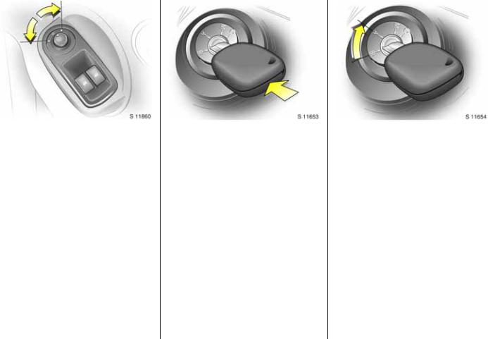
Electrically adjustable exterior mirrors 3:
Switch in driver’s door
Only operational with the ignition on.
Turn switch to left:
switch operates left-hand mirror.
Turn switch to right:
switch operates right-hand mirror.
Switch in central position: mirror adjustment is off.
The lower aspherical mirrors can be adjusted manually.
Starter switch:
St |
= |
Ignition off |
A |
= |
Steering unlocked, ignition off |
M |
= |
Ignition on: preheat (see page 14) |
D |
= |
Start (transmission in neutral) |
6 Electronic immobiliser - see page 30.
Releasing the steering column lock:
Move steering wheel slightly, turn key to position ‘A’
6 Remove key and engage steering column lock - see page 16.

6 In brief

In brief |
7 |
|
|
Page |
1 |
Door window defrosters ................... |
73 |
2 |
Side air vents .................................... |
73 |
3 |
Passenger’s airbag 3 |
|
|
or storage area ................................. |
52 |
4 |
Centre air vents ................................ |
72 |
5 |
Radio / Infotainment system 3........ |
27 |
6 |
Heating and ventilation controls |
.... 71 |
7 |
Electronic tachograph 3 .................. |
27 |
8Stalk for driving lights, headlight flash, front fog lights, fog tail light,
|
dipped and main beam |
................... 10 |
|
turn signals ....................................... |
11 |
|
horn.................................................... |
11 |
9 |
Driver’s airbag................................... |
52 |
10 |
Instruments............................ |
18, 22, 23 |
|
|
Page |
11 |
Stalk for windscreen wiper, |
|
|
automatic wiper with rain sensor 3, |
|
|
windscreen wash system, |
|
|
headlight wash system 3................. |
12 |
12 |
Drink holder or storage area |
|
13 |
Starter switch ...................................... |
5 |
14 |
Instrument panel fusebox .............. |
127 |
15 |
Headlight range adjustment 3 ....... |
64 |
16 |
Battery isolation switch 3 .............. |
126 |
17 |
Switches for |
|
|
heated rear windows........................ |
15 |
|
air suspension 3 ............................... |
98 |
|
cruise control 3................................. |
99 |
|
speed limiter 3................................ |
100 |
|
Winter and Laden programme |
|
|
with Tecshift 3. ........................... |
82, 83 |
|
rear seating |
|
|
compartment lights 3 ...................... |
65 |
|
ESP 3 |
|
|
(Electronic Stability Programme)..... 96 |
|
|
|
Page |
18 |
Hazard warning switch .................... |
11 |
19 |
Ashtray .............................................. |
45 |
20 |
Document holder.............................. |
47 |
21 |
Cigarette lighter................................ |
44 |
22 |
Note pad clip 3 ................................ |
47 |
|
rear door lock isolation switch 3..... |
38 |
|
rear seating |
|
|
compartment lights 3...................... |
65 |
23 |
Glove compartment |
|
24 |
Bonnet release lever......................... |
39 |

8 In brief
Control indicators
vAirbag system: see page 52.
rFog tail light: see pages 10, 63.
>Front fog lights 3: see page 63.
ßHeated front seats 3: see pages 18, 79.
uAnti-lock Brake System (ABS): see page 106.
8Diesel particle filter 3: see pages 18, 93.
ZExhaust emissions 3: see pages 20, 93.
UCruise control, speed limiter 3: see page 100.
L |
Rear door lock isolator 3: |
|
see page 38. |
o |
Not used |
CStop engine: see page 19.
oElectronic immobiliser: see pages 19, 30.
AService / engine electronics 3: see pages 19, 93.
OTurn signals: see pages 11, 19.
YFuel level:
see pages 19, 91, 154.
IOil pressure: see page 20.
D |
Engine electronics / Preheating |
|
system / Diesel fuel filter: |
|
see pages 14, 19. |
EEngine stop: see page 19.
pAlternator: see page 20.
RBrake system:
see pages 20,105, 142.
v ESP (Electronic Stability
Programme) 3: see page 96.
XDriver’s seat belt 3: see pages 20, 48.
H Not used
PHeadlight main beam: see pages 10, 62.
9Headlight dipped beam: see pages 10, 62.
H |
Air suspension: Fault 3: |
|
see page 20. |
PElectric side step 3: see page 37.
FEngine oil life monitor 3: see page 94.
Windscreen wiper
Stalk positions: see page 12,
KTimed interval wipe or automatic wiping with rain sensor 3
1Slow
2Fast
nWindscreen wash and headlight wash 3

In brief |
9 |
Lighting - see pages 10, 62.
7 Light switch off position
0 Parking lights
9 Headlight dipped beam
P Headlight main beam r Fog tail light
>Front fog lights 3
OTurn signals: see pages 11, 19.
¨Hazard warning lights: see pages 11, 63.
?Headlight range adjustment 3: see page 64.
dInterior light: see page 64.
lReading light: see page 65.
Heating and ventilation
xFan switch: see page 72.
Air distribution: see page 71,
M to head area.
L to head area and footwell
K to footwell
Jto windscreen, front door windows and to footwell
Kto demist windscreen and front door windows
Jto defrost windscreen and front door windows
ÜHeated rear windows 3, heated exterior mirrors 3: see pages 15, 75.
AC Air conditioning system 3: see page 75.
;Air recirculation button: see page 76.
ßHeated seats 3: see pages 18, 79.
Tecshift 3
VWinter programme: see page 82.
kg Laden programme: see page 83.
WTransmission electronics: see page 85.
TFootbrake application: see page 80.
AAutomatic mode: see page 81.
Miscellaneous
jHorn:
see page 11.
/Bonnet:
see page 39.
UCentral locking: see page 34.
) Cigarette lighter 3: see page 44.
+First-aid kit 3: see page 119.
¨Warning triangle 3: see page 119.
10 In brief
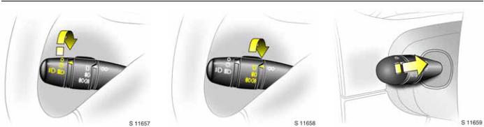
Light switch: |
Fog lights: |
|
Dipped and main beam, |
|||
7 = |
Off |
7 |
= |
Off |
Headlight flash: |
|
0 = |
Parking lights |
r |
= |
On (fog tail light only) |
Pull stalk towards steering wheel |
|
9 = |
Dipped or main beam |
> r |
= |
On (front fog lights 3 |
To change the headlight beam, pull the |
|
6 Headlight warning device - see page 16, |
|
|
and fog tail light) |
stalk towards the steering wheel, then |
||
Further information - see page 62, |
The fog tail lights will only illuminate when |
release when a click is felt. |
||||
Automatic dipped beam activation 3 - |
Pulling the stalk towards the steering wheel |
|||||
the headlights and ignition are switched |
||||||
see page 63, |
||||||
on. |
|
|
to the first stop operates the headlight |
|||
headlight range adjustment - see page 62, |
|
|
||||
|
|
|
flash. |
|||
headlights when driving abroad - |
|
|
|
|||
|
|
|
|
|||
see page 66. |
|
|
|
|
||
|
|
|
|
|
|
|
In brief |
11 |
|
|
|
|
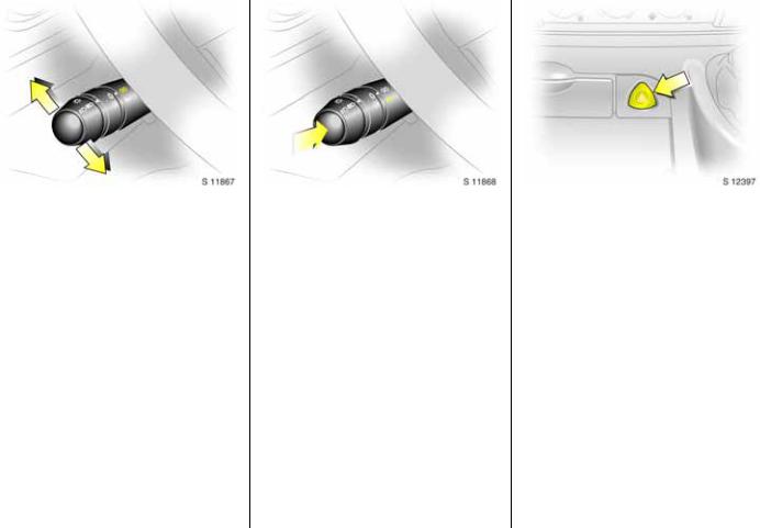
Turn signals: |
|
Horn: |
Stalk in rest position |
Press button j |
|
Upwards = |
Right turn |
|
Downwards = |
Left turn |
|
When the steering wheel is turned back, the stalk automatically returns to its original position. This will not happen when making a minor steering manoeuvre such as lane changing.
When lane changing, move stalk part way to first stop. When released, the stalk will spring back.
Hazard warning lights:
On |
= |
Press button ¨ |
Off |
= |
Press button ¨ again |
When the hazard warning system is actuated, the button's control indicators flash in unison with the hazard warning lights.
12 In brief
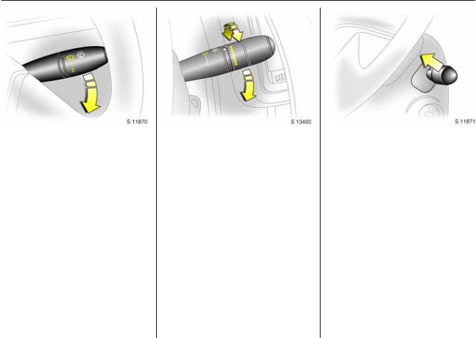
Windscreen wiper: |
Automatic wiping with |
Windscreen wash system and |
|||||
Move stalk downwards |
rain sensor 3: |
|
headlight wash system 3: |
||||
K = |
Timed interval wipe |
Move stalk downwards |
Pull stalk towards steering wheel |
||||
1 |
= |
Slow |
K = |
Automatic wiping with |
Wash fluid is sprayed onto the windscreen |
||
2 |
= |
Fast |
|
|
rain sensor |
(and - when the lights are on - onto the |
|
Return the stalk to its original position to |
1 |
= |
Slow |
|
headlights 3); at the same time, the wiper |
||
switch off. |
2 |
= |
Fast |
|
is operated for several cycles. |
||
|
|
|
The rain sensor detects the amount of |
Check regularly that the headlight wash |
|||
|
|
|
water on the windscreen and automatically |
system is operating efficiently. |
|||
|
|
|
regulates the windscreen wiper frequency. |
On vehicles fitted with rain sensor 3, it is |
|||
|
|
|
The sensitivity of the system can be |
important to keep the sensor area clean by |
|||
|
|
|
adjusted by rotating the variable wipe: |
operating the wash system regularly. |
|||
|
|
|
Less sensitive |
= rotate down |
6 Further information - see pages 143, 144. |
||
|
|
|
More sensitive |
= rotate up |
|
||
Upon starting the engine, automatic wiping will need to be reselected.
6 Further information - see pages 143, 148.
In brief |
13 |
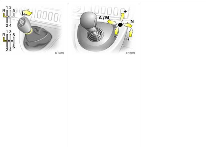
Manual transmission:
o |
= |
Neutral |
1 to 5/6 |
= 1st to 5th / 6th 3 gear |
|
R |
= |
Reverse gear |
When shifting up from 4th to 5th gear, pressure must be exerted towards the right at the beginning of the shift operation.
When shifting from 5th to 4th gear, do not exert any force towards the left.
Reverse gear:
With vehicle stationary, depress clutch pedal, pull up collar 3 on gearshift lever and move lever against resistance to engage reverse gear.
If the gear does not engage:
With gearshift lever in neutral, release clutch pedal and depress again, then repeat gear selection.
Tecshift 3: |
|
|
N |
= |
Neutral |
o |
= |
Centre position |
-= Shift to lower gear
+= Shift to higher gear
A/M |
= |
Switch between |
|
|
Automatic mode |
|
|
and Manual mode |
R |
= |
Reverse |
The selector lever must be moved in the appropriate direction as far as it will go. Upon release, it automatically returns to the centre position. Pay heed to the gear / mode indicator in the transmission display.
6 Further information - see page 80.
Before driving, check:
z Tyre inflation pressures and condition.
zEngine oil level and fluid levels in engine compartment (see pages 137 to 138).
z All windows, mirrors, exterior lighting and number plates are free from dirt, snow and ice and are operational.
zObjects are securely located and will not be thrown forwards in the event of sudden braking.
zNo objects are placed on the instrument panel or in the area in which the airbags inflate.
z Seats, seat belts and mirrors are correctly adjusted.
z Brake operation.
14 In brief
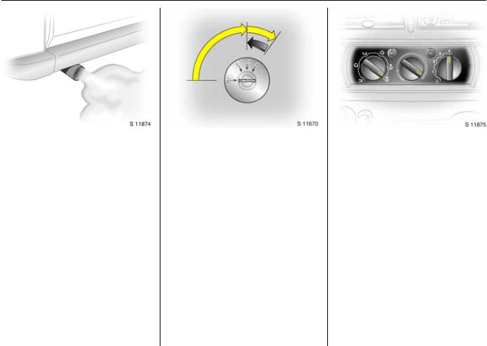
Exhaust gases are poisonous |
Starting the engine: |
Demisting windows: |
|
Exhaust gases contain carbon monoxide, |
Transmission in neutral, |
Set the temperature rotary knob |
|
which is extremely poisonous but has no |
Depress clutch pedal, |
to red and fan to position 4, |
|
odour or colour. |
Do not accelerate, |
set air distribution to K2) |
|
Therefore, never inhale exhaust gases, and |
Turn key to M, |
Close centre air vents; open side air vents |
|
never run the engine in an enclosed space. |
Wait until preheating control |
and direct them towards the door windows. |
|
You should also avoid driving with the |
indicator D goes out1), |
6 Heating, ventilation - see page 71, |
|
turn key to D |
|||
doors open, as exhaust gases could enter |
air conditioning system - see page 75. |
||
the passenger compartment. |
6 Electronic immobiliser - see page 30, |
|
|
6 Exhaust gases - see page 92. |
further information - see pages 80, 88. |
|
|
|
|
2) |
Air recirculation feature not possible when |
|
position selected. On vehicles equipped with |
1) Preheating system switches on only if outside |
air conditioning 3, the air conditioning is |
automatically activated when position |
|
temperature is low. |
selected. |
In brief |
15 |
|
|
|
|
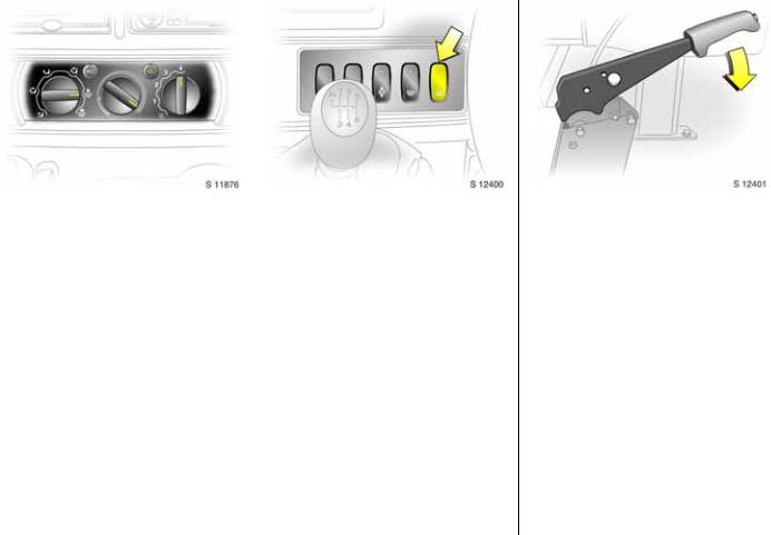
Defrosting windows: |
Heated rear windows 3, |
||
Set the temperature rotary knob |
heated exterior mirrors 3: |
||
to red and fan to position 4, |
Press Ü |
= |
On |
set air distribution to J |
Press Ü again= |
Off |
|
Close centre air vents; open side air vents |
6 Further information - see page 75. |
||
and direct them towards the door windows. |
|
|
|
6 Heating, ventilation - see page 71, |
|
|
|
air conditioning system - see page 75. |
|
|
|
|
|
|
|
Releasing the handbrake: Raise lever slightly,
press lock button, lower lever fully
Drive carefully, economically and with the environment in mind. While driving, do not do anything that could distract you.
6 Handbrake - see page 104.
16 |
In brief |
|
|
||
|
|
|
|
||
Warning buzzers |
|
When parking: |
|||
|
|||||
While driving: |
|
z Always apply handbrake firmly. Engage |
|||
z when operating the turn signals. |
|
first gear or reverse gear. On slopes |
|||
|
apply the handbrake as far as it will go. |
||||
z when switching cruise control 3 on and |
|
||||
|
z Turn steering wheel until lock is felt to |
||||
|
off. |
|
|
||
|
|
|
engage (anti-theft protection). |
||
z during illumination of low fuel control |
|
||||
|
z Switch off exterior lights, otherwise the |
||||
|
indicator. |
|
|||
|
|
headlight warning device will sound |
|||
z with Tecshift 3, at high clutch |
|
||||
|
when the driver’s door is opened. |
||||
|
temperatures. |
|
z Cooling fans may run on after the engine |
||
z when driver’s seat belt is not fastened 3. |
|
||||
|
has been switched off. |
||||
When the vehicle is parked and driver’s |
|
z Do not park vehicle on easily ignitable |
|||
|
surfaces as the hot exhaust system |
||||
door is opened: |
Parking the vehicle: |
||||
temperatures could cause the surface to |
|||||
|
|
|
|||
z when headlights are switched on. |
Apply handbrake firmly, |
ignite. |
|||
z with Tecshift 3, when neutral is not |
Close windows, |
|
|||
|
selected, footbrake is not depressed or |
Switch off engine, |
|
||
|
handbrake is not applied. |
Remove key, |
|
||
6 Driving hints - see page 86, |
Engage steering column lock, |
|
|||
Save fuel, protect the environment - |
Lock doors |
|
|||
see page 88. |
6 Further information - see pages 30, 87, |
|
|||
|
|
|
remote control - see page 31, |
|
|
|
|
|
central locking system - see page 33, |
|
|
|
|
|
Vauxhall alarm system 3 - see page 35. |
|
|
|
|
|
|
|
|

In brief |
17 |
Service work, Maintenance
We recommend that you entrust all work to your Vauxhall Authorised Repairer, who can provide you with reliable service and correctly perform all work according to factory instructions.
If you have a problem - see page 134.
Genuine Vauxhall Parts and Accessories
We recommend the use of “Genuine Vauxhall Parts and Accessories” and conversion parts released expressly for your vehicle type. These parts have undergone special tests to establish their reliability, safety and specific suitability for your vehicle. Despite continuous market monitoring, we cannot assess or guarantee these attributes for other products, even if they have been granted approval by the relevant authorities or in some other form.
"Genuine Vauxhall Parts and Accessories" and conversion parts approved by Vauxhall can be obtained from your Vauxhall Authorised Repairer. You will be given advice about permitted technical changes and correct installation will take place.
9Warning
Carry out regularly the checks recommended in this Owner's Manual.
Ensure that your vehicle is serviced at the service intervals specified in the Service Booklet. We recommend that you entrust this work to your Vauxhall Authorised Repairer.
Have faults remedied without delay! Consult a workshop. We recommend your Vauxhall Authorised Repairer. If necessary, interrupt your journey.
6 Maintenance - see pages 136 to 146.
That was a brief overview of the most important information for your first drive in your Movano.
Your vehicle has still more instruments and controls, possibly also optional equipment.
The remaining chapters of the Owner’s Manual contain important information on operation, safety and maintenance as well as a complete index.
18 Instruments
Instruments
Control indicators ............................... |
18 |
Tachometer......................................... |
21 |
Speedometer....................................... |
21 |
Fuel gauge .......................................... |
21 |
Coolant temperature gauge.............. |
22 |
Multi-function display ........................ |
22 |
Oil level display 3............................... |
23 |
Trip computer 3 ................................. |
24 |
Engine oil life monitor 3..................... |
27 |
Radio 3................................................ |
27 |
Electronic tachograph 3.................... |
27 |
Navigation system 3.......................... |
28 |
Mobile telephones and radio |
|
equipment (CB) 3 ............................ |
28 |
Control indicators
The control indicators described here are not present in all vehicles. The descriptions however, apply to all instrument versions.
Ü
Heated rear windows 3, heated exterior mirrors 3 see pages 15, 75.
9
Headlight dipped beam
Illuminates when dipped beam is on.
P
Headlight main beam
Illuminates when main beam is on and when headlight flash is operated.
r
Fog tail light
Illuminates when fog tail light is switched on.
>
Front fog lights 3
Illuminates when front fog lights are switched on.
u
Anti-lock Brake System (ABS) see page 105.
8
Diesel particle filter 3
Illuminates when regeneration of diesel particle filter is required - see page 93.
ß
Heated front seats 3
Illuminates when seat heating system is switched on.

Instruments 19
P
Electric side step 3
Illuminates when electric side step is activated by operating sliding side door. If illuminated continuously it indicates a fault. Consult a workshop.
v
ESP (Electronic Stability Programme) 3 see page 96.
F
Engine oil life monitor 3 see page 94.
O
Turn signals
Flashes when turn signals are on. If they flash rapidly: a turn signal bulb has failed.
kg
Tecshift, Laden programme 3
Control indicator illuminates in transmission display when Laden programme is enabled - see page 83.
T
Tecshift, footbrake application 3 see page 80.
W
Tecshift, transmission electronics 3
Control indicator illuminates in transmission display when fault has occurred - see page 85.
A
Tecshift, Automatic mode 3
Control indicator illuminates in transmission display when Automatic mode is selected - see page 81.
V
Tecshift, Winter programme 3
Control indicator illuminates in transmission display when Winter programme is enabled - see page 82.
C
Stop engine
If C illuminates in conjunction with either p, I, or E, stop engine as soon as possible without impeding other vehicles and consult a workshop.
o
Electronic immobiliser
If it flashes when the ignition is on, there is a fault in the immobiliser system;
the engine cannot be started - see page 30.
A
Service / engine electronics 3
If it illuminates while driving, interrupt your journey. If illuminated in conjunction with another control indicator, observe this also. Consult a workshop.
Further information - see page 93.
D
Engine electronics / Preheating system / Diesel fuel filter
Illuminates briefly during engine preheating. If illuminated continuously it indicates:
z The presence of water in the diesel fuel filter. Drain diesel fuel filter of residual water - see page 140.
z An electronic system failure or the presence of water in the diesel fuel filter. Consult a workshop.
Y
Fuel level
If it illuminates: fuel level low, fill up. Never let the tank become empty!
To start the engine after the tank has been run empty, the fuel system must be bled - see page 115.
E
Engine stop
Illuminates in conjunction with control indicator C (stop engine) if coolant temperature is too high. Stop vehicle and consult a workshop.
20 |
Instruments |
|
|
|
|
|
|
|
|
|
|
|
|
|
|
p |
|
|
|
|
F |
||
|
|
9Warning |
|
||||
Alternator |
|
|
Not used |
||||
Illuminates when ignition is switched on. |
|
|
|
X |
|||
|
When the engine is off, considerably |
|
|||||
Goes out after engine is started. |
|
|
|||||
If illuminated during driving: |
|
greater force will be required for braking |
|
Driver’s seat belt 3 |
|||
|
and steering. |
|
Illuminates when ignition is switched on to |
||||
Stop vehicle and switch off engine. The |
|
|
|||||
|
Do not remove key until vehicle has come |
|
remind driver to engage seat belt. |
||||
battery is not being charged and the |
|
|
|||||
|
|
Seat belts - see page 48. |
|||||
engine cooling may be interrupted. The |
|
to a standstill, otherwise the steering |
|
||||
|
|
|
|
||||
brake servo unit may cease to be effective. |
|
column lock could engage unexpectedly. |
|
o |
|||
Interrupt your journey and check drive belt |
|
|
|
Not used |
|||
|
|
|
|||||
condition and tensioning before consulting |
|
Check oil level before consulting a |
|||||
|
|
|
|||||
a workshop. |
|
U |
|||||
|
workshop. |
||||||
I |
|
|
R |
Cruise control, speed limiter 3 |
|||
|
|
see page 100. |
|||||
Oil pressure |
|
Brake system |
|
|
|||
Illuminates when ignition is switched on. |
|
Illuminates when ignition is switched on if |
Z |
||||
Goes out after engine is started. |
|
handbrake is applied and/or fluid level for |
Exhaust emissions 3 |
||||
If illuminated during driving: |
|
brake hydraulics is too low. |
If it illuminates, there is a fault in the |
||||
Engine lubrication may be interrupted, |
|
|
|
emission control system. The permitted |
|||
|
9Warning |
|
|||||
resulting in damage to the engine and/or |
|
|
emission limits may be exceeded. Consult a |
||||
locking of the driving wheels: |
|
|
|
workshop. |
|||
|
If it illuminates when the handbrake is not |
|
|||||
z Move out of the flow of traffic as quickly |
|
|
For faults that can lead to destruction of |
||||
|
applied: stop vehicle; interrupt your |
|
|||||
|
as possible without impeding other |
|
|
the catalytic converter - see page 92. |
|||
|
|
journey immediately and consult a |
|
||||
|
vehicles. |
|
|
Consult a workshop immediately. |
|||
|
|
workshop. |
|
||||
z Depress clutch. |
|
|
|
|
|||
|
|
|
H |
||||
z Move gearshift lever to neutral. |
|
|
|
||||
|
|
|
|||||
|
|
|
Air suspension: Fault 3 |
||||
z Switch off ignition (to position A). |
|
Further information - see page 103. |
|||||
|
|
|
|
L |
Illuminates when a fault has occurred in the |
||
|
|
|
|
air suspension system. Consult a workshop. |
|||
|
|
|
|
Rear door lock isolator 3 |
|
|
|
|
|
|
|
see page 38. |
|
|
|
|
|
|
|
v |
|
|
|
|
|
|
|
Airbag system |
|
|
|
|
|
|
|
see page 52. |
|
|
|
|
|
|
|
|
|
|
|
Instruments 21
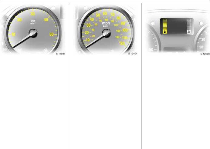
Tachometer
Making use of the tachometer helps to save fuel; it indicates the engine speed.
Warning zone on right:
Maximum permissible engine speed exceeded, danger to engine.
If possible, drive in each gear in the low engine speed range (between approx. 2000 and 3000 rpm) and maintain an even vehicle speed.
Start-up limiter 3
To reduce the risk of engine damage on certain models, engine rpm will be limited when starting.
Speedometer
Indicates the vehicle speed.
Certain vehicle variants feature a speed regulator 3 1) which restricts the vehicle’s maximum speed. As a visible indication of this, a warning label is located on the instrument panel.
Vehicles with cruise control may feature a speed limiter 31) (which enables a variable maximum vehicle speed to be set) -
see page 100.
1)Depending on driving environment (e.g. when descending steep inclines), the vehicle speed can exceed set limits. In such instances, it remains the driver’s responsibility to adhere to the specific speed limits.
Fuel gauge
Display of fuel level:
Illumination of bars displays fuel level.
When the fuel gauge indicates that the fuel supply is low, low fuel level control indicator Y illuminates = fill up.
See page 90.
Never let the tank become empty!
22 Instruments
Coolant temperature gauge
Display of coolant temperature:
Bars illuminated |
= |
Engine operating |
in lower area |
|
temperature not yet |
|
|
reached |
Bars illuminated |
= |
Normal operating |
up to central |
|
temperature |
area |
|
|
Bars illuminated |
= |
Temperature too |
to uppermost |
|
high. Stop vehicle, |
area |
|
switch off engine. |
or control |
|
Danger to engine. |
indicator E is |
|
Check coolant level. |
illuminated 3 |
|
See page 141. |
For physical reasons, the coolant temperature gauge shows the coolant temperature only if the coolant level is adequate.
During operation, the system is pressurized. The temperature may therefore rise to over 100 °C.
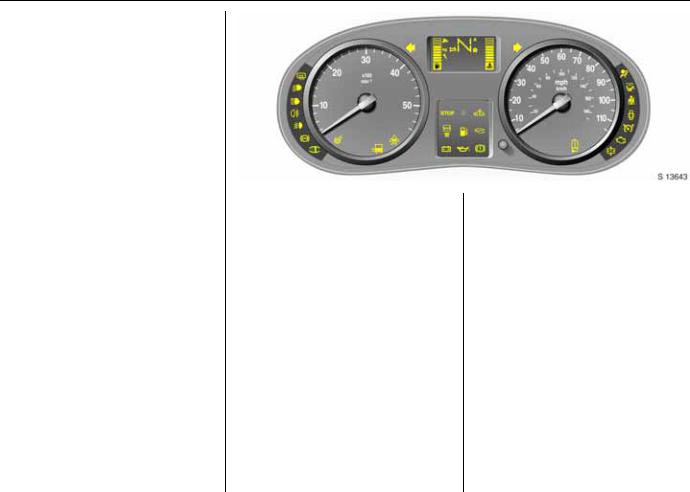
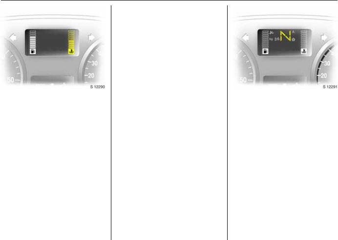
Multi-function display
Transmission display 3
Display of the selected gear and mode with Tecshift 3.
N Neutral or idling position. R Reverse gear.
A Automatic mode. kg Laden programme.
VWinter programme.
TFootbrake application.
WTransmission electronics.
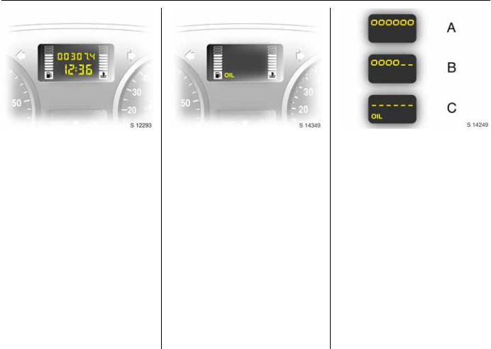
Instruments 23
Electronic odometer / clock 3 Normal mode:
The odometer and clock are visible.
Reset:
The reset button is located alongside the speedometer. Press button once to display the trip odometer.
Press the button and hold; the display will flash and after 1 second will reset to zero. Press the button again to return the odometer to normal mode.
Clock adjust mode:
With the display in normal mode, press and hold the button and the minutes reading will begin to increase.
After the button is released, the clock will continue to flash for a further 5 seconds to enable further adjustments to be made.
Oil level display 3
The oil level display is correct only if the vehicle is parked on level ground with a cold engine. The oil level display will only be reset if the ignition has been switched off for more than two minutes.
If "oil" appears in the display, the oil level may need topping up. To gain a more accurate indication of the oil level, press and hold the reset button - see page 26.
The squares that appear on the display indicate the level. As the oil level diminishes, the squares in the display disappear and are replaced with dashes.
A:Maximum level
B:Intermediate level
C:Minimum level = check and top up engine oil1)
1)Control indicator Ailluminates if oil level is too low.
To return to the normal display, press the reset button again.
Checking and topping up fluids - see page 138.
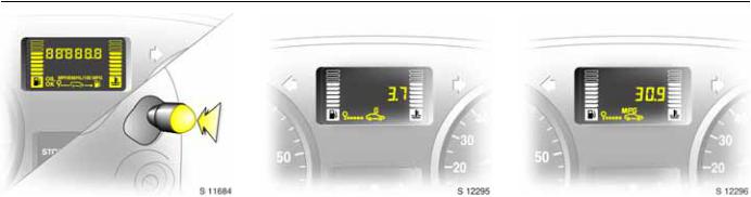
24 Instruments
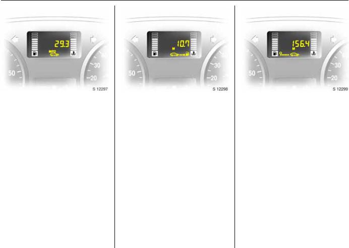
Trip computer 3 |
Fuel used |
Average consumption |
|
In addition to the electronic odometer |
Displays the amount of fuel consumed |
Displays the average amount of fuel |
|
since the last reset. |
consumed, taking into consideration the |
||
functions, the trip computer can also |
|||
|
distance travelled and the fuel used since |
||
display additional monitored vehicle data. |
The measurement can be restarted at any |
||
the last reset. |
|||
z Fuel used, |
time - see page 26. |
||
The measurement can be restarted at any |
|||
|
|||
z Average consumption, |
|
||
|
time - see page 26. |
||
|
|
||
z Instantaneous consumption, |
|
|
|
z Range, |
|
|
|
z Distance travelled, |
|
|
|
z Average speed, |
|
|
|
z Cruise control speed limiter 3. |
|
|
|
Pressing the selection switch located on the |
|
|
|
end of the windscreen wash control stalk |
|
|
|
will cycle through these displays. |
|
|
|
|
|
|
Instruments 25
Instantaneous consumption
Displays the current fuel consumption level.
The value is displayed after reaching a speed of 15 mph (25 km/h).
Range
Displays the distance the vehicle can travel on its current fuel tank contents.
The range is calculated from the current contents of the fuel tank and the average consumption since the last reset -
see page 26.
The measurement can be restarted at any time - see page 26.
Distance travelled
Displays the distance driven since the last reset.
The measurement can be restarted at any time - see page 26.
 Loading...