


I N S T A L L A T I O N & O P E R A T I O N G U I D E
MSU250
INFRARED MAIN SYSTEM UNIT
B L E N D I N G H I G H F I D E L I T Y A N D A R C H I T E C T U R E ®

I N F R A R E D M A I N S Y S T E M U N I T
MSU250
Infrared Main
System Unit
TABLE OF CONTENTS |
Introduction |
||
Introduction |
1 |
An infrared (IR) extender system enables you to control your IR |
|
remote controlled A/V equipment from a remote location. This |
|||
Features and |
|
||
|
enables you to place your A/V components out of sight |
||
Benefits |
2 |
||
(behind cabinet doors, in the rear of a room, or in a different |
|||
MSU250 Parts |
|
||
4 |
room) and still conveniently operate your equipment. |
||
Guide |
Installed at the equipment location, the MSU250 receives the |
||
Installation |
|
||
|
IR commands transmitted from your existing hand-held |
||
Considerations |
5 |
||
remotes in that room. The commands are carried via a small |
|||
Installation |
8 |
||
category 5 cable to your A/V equipment in another room, and |
|||
Testing the |
|
instantly “repeated”. |
|
IR Extender |
|
The MSU250 is compatible with all current Niles infrared systems. |
|
System |
11 |
||
It may be used along with the Niles TS100, MS100, MS200, |
|||
Power Status |
13 |
||
WS100, MVC100IR and CS100 IR sensors or the IntelliPad®. |
|||
Trouble- |
|
The model MSU250 is an IR Main System Unit. It is one of |
|
Shooting |
16 |
||
three elements that make up an infrared extender system: |
|||
Specifications |
19 |
||
• IR Main System Unit—Models MSU140, MSU250, |
|||
Contents |
19 |
||
MSU480 and MSU440Z. |
|||
Addendum |
20 |
||
• IR Sensors/Keypads—Models WS100, TS100, MS100, |
|||
|
|
||
|
|
MS200, CS100, MVC100IR and the IntelliPad. |
|
|
|
• IR Flashers—Models MF1, MF2, MF1VF, MF2VF and |
|
|
|
the IRB1. |
|
|
|
An IR sensor expansion unit, Model IRH610, is available for |
|
|
|
IR repeater systems used in more than six rooms. |
|
|
|
|
|

I N F R A R E D M A I N S Y S T E M U N I T
Features and Benefits
The MSU250 offers a number of improvements over other IR Extender Main System Units:
•Universal system—compatible with virtually all brands of A/V equipment and remote controls.
•Accommodates two IR sensors or keypads.
•Provides five flasher outputs via convenient 3.5mm jacks.
•System feedback LED confirms operation.
•12VDC Output—This is useful for triggering external devices and system automation.
•3-30V AC/DC status input. Provides system status to connected sensors and keypads.
•Expandable—an IRH610 IR expansion hub can be used to provide additional inputs.
•2x variable flasher out (4 + 5).
•Printed circuit board design assures high reliability.
•Low profile and small footprint with integrated mounting wings that allow for both horizontal and vertical installation.
•UL listed regulated in-line power supply with universal voltage capability.
•Two year parts and labor warranty.
2
I N F R A R E D M A I N S Y S T E M U N I T
Niles IR |
Stereo Receiver |
|
Flasher |
||
|
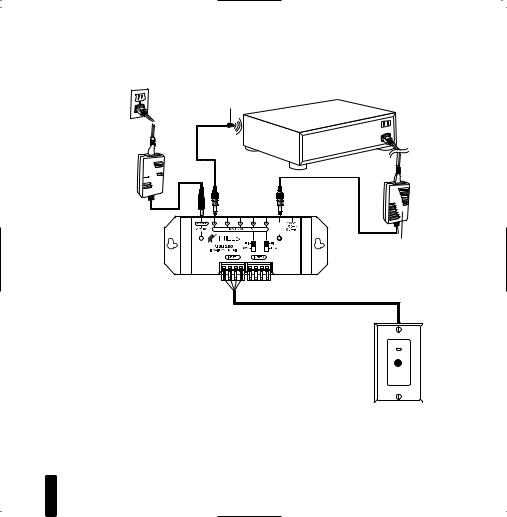
12VDC power supply  (supplied with the
  MSU250 Main
  System Unit) plugged
  into an unswitched
 AC outlet powers
 the system
3- |
MSU250 |
12VDC power supply (Not Supplied) plugged into the switched outlet Niles stock#FG00665
Figure 1
Connecting the WS100 to a Niles MSU250 Main System Unit broadcasting a status feedback signal.
In a typical system, the MSU250 provides for the connection for two remote room sensors (or keypads) and will control multiple audio/video components via its flasher connections.
Power, IR data, status signal and ground via category 5 wire
WS100 IR Sensor
3

I N F R A R E D M A I N S Y S T E M U N I T
MSU250 Parts Guide
1 |
2 |
4 |
3 |
||
|
3-30V |
|
|
AC/DC |
|
|
STATUS |
|
|
IN |
|
|
6 |
5 |
|
7 |
|
1.12VDC Jack – Provides 12 volt DC power to MSU via a regulated power supply.
2.IR Flasher Outputs – 3.5mm jacks provide output for either single or dual (MF1, MF1VF, MF2, MF2VF) low-level flashers.
3.3-30V AC/DC Status – 3.5mm jack provides system status to sensors/ keypads via a 12V power supply attached to a switched outlet on the system receiver or a 12V trigger output.
4.12V Output – When 12 volts is detected at the status jack (#3) the 12V output jack will output 12V/200mA DC. This is useful for triggering external devices and system automation.
5.Status/IR Confirmation LED – This LED performs two functions: (1) it provides a visible indication of system status via a green LED and (2) confirms the reception of IR data via a blinking blue LED.
6.Flasher Hi/Lo switch – Setting these switches to the appropriate position allows you to connect either a high output flooding flasher (IRB1) or low output microflashers (MF1, MF1VF, MF2, MF2VF).
7.Sensor Input – Removable quick connect sensor plug for connection of IR sensors to the system.
4
I N F R A R E D M A I N S Y S T E M U N I T
Installation Considerations
IMPORTANT
Do not place the MSU250 on top of or directly behind a television set. Some television sets produce intense electromagnetic interference which may disable your IR extender system.
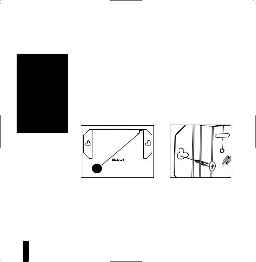
Placement of the MSU250
Place the MSU250 conveniently close to the equipment it will be controlling. Generally, the unit is placed in a concealed location because its controls and indicators are only used during installation. Placement possibilities include:
1)Table-top (on the floor or shelf behind the equipment) (Figure 2).
2)Wall-mount (affixed to the back of the equipment cabinet or a nearby wall) (Figure 3).
3-30V |
4 |
3 |
2 |
1 |
POWER |
AC/DC |
|
|
|
|
+12VDC |
STATUS |
|
|
|
|
|
MSU250 Base |
|||||
IN |
|
FLASHEROUTPUTS |
|
|
|
|
MSU140 |
|
|
|
|
IRMAINSYSTEMUNIT |
|
|
|
||
|
|
INPUT1 |
|
|
|
|
|
Self-Adhesive |
|||
|
|
Rubber Feet |
|||
POWER |
+12V DC |
Figure 2: Table-top placement |
Figure 3: Wall-mount placement |
Affix the enclosed self-adhesive |
Use sheetrock screws. |
rubber feet to the base of the MSU250. |
|
5
I N F R A R E D M A I N S Y S T E M U N I T
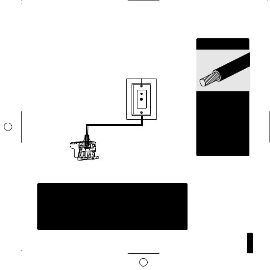
Wiring
From every IR Sensor location you must “home-run” a category 5 cable back to the MSU250. Home run means that an individual cable is connected between each IR Sensor and
the MSU250 (Figure 4).
Remotely Located
IR Sensors
Figure 4: Home run the sensor cable from the sensor to the MSU250.
SENSORS IN
SD G +
TA N 12 D VA T
T A
U
S
“TECH TIP”
Wire size is expressed by it’s AWG (American Wire Gauge) number. The lower the AWG number, the larger the wire, i.e., 20 AWG wire is physically larger than
22 AWG.
IMPORTANT – AVOIDING INTERFERENCE
Avoid locating any of the cables, Sensors, Keypads or the Main System Unit near any potential sources of ElectroMagnetic Interference (EMI), such as light dimmers, speed controls for ceiling fans, electrical ballasts, television sets, large motors, heaters or air conditioners.
6
I N F R A R E D M A I N S Y S T E M U N I T
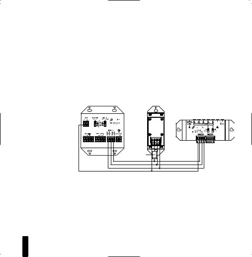
Figure 5: An IR sensor cable is “daisy-chained” from an IntelliPad, to a sensor and back to the MSU250.
IntelliPad Wiring
When you are placing both a IntelliPad and a sensor (or two keypads) in one room you may “daisy-chain” using a single cable. A cable is run between the keypad and the sensor and a single cable is run from either the sensor back to the MSU250. To prevent data feedback an IN4003 Blocking Diode is inserted on the data (IR) line between the IntelliPad and the sensor. The cathode, or blocking side of the diode, faces the IntelliPad. (Figure 5). Note that status wire is connected to IntelliPad’s status (+) connector.
3-30V |
AC/DC |
STATUS |
IN |
IN4003 |
Blocking |
Diode |
Sensor/Keypad Cable
The MSU250 connects to IR sensors and the IntelliPad with category 5 cable, with a maximum cable run of 500'.
Flasher Cable
Niles infrared flashers come supplied with a 10 foot 2-conduc- tor 22 gauge cable. Should you need to extend it, use a 16 gauge 2-conductor cable (“zip-cord”). Shielding is not necessary for a flasher. Flasher wires can be extended up to 200'.
7
 Loading...