


 Loading...
M350 E 05.4.NF.1
Industrial Microscope
ECLIPSE LV150/LV150A
Instructions
Thank you for purchasing the Nikon products.
This instruction manual has been prepared for the users of Nikon’s industrial microscope “ECLIPSE LV150/LV150A.”
To ensure correct usage, read this manual carefully before operating the instrument.
•It is prohibited to reproduce or transmit this manual in part or whole without Nikon’s expressed permission.
•The contents of this manual are subject to change without notice.
•Although every effort has been made to ensure the accuracy of this manual, if you note any points that are unclear or incorrect, contact your nearest Nikon representative.
•Some of the products described in this manual may not be included in the set you have purchased.
•Be sure to read the instruction manual for any other products that may be used in combination with the microscope.
Warning/Caution Symbols Used in This Manual
Although Nikon products are designed to provide you with the utmost safety during use, incorrect usage or disregard of the instructions can cause personal injury or property damage. For your safety, read this instruction manual carefully and thoroughly before using the instrument. Do not discard this manual, but keep it near the product for easy reference.
In this manual, safety instructions are indicated with the symbols shown below. Be sure to follow the instructions indicated with these symbols to ensure correct and safe operation.
|
Symbol |
|
Meaning |
|
|
|
WARNING |
|
Disregarding instructions marked with this symbol may lead |
|
|
|
||
|
|
|||
|
|
|
to death or serious injury. |
|
|
|
CAUTION |
|
Disregarding instructions marked with this symbol may lead |
|
|
|
||
|
|
|||
|
|
|
to injury or property damage. |
|
|
|
|
|
|
Meaning of Symbols Used on the Equipment
Symbol Meaning
Caution for heat.
This marking on the rear of the lamphouse, and near the lamphouse clamp screw on the illuminator (LV-UEPI and LV-UEPI2), calls your attention on the following.
For the symbol position, see pages 10 and 12.
•The lamphouse is very hot during and immediately after illumination.
•Risk of burns. Do not touch the lamphouse during and immediately after illumination.
•Make sure that the lamphouse has sufficiently cooled before replacing the lamp.
1

 WARNING
1.Intended product use
This microscope should only be used for microscopic observation. Do not use it for any other purpose. Do not observe such a large sample as to stick out of the stage.
2.Do not disassemble.
Disassembly may cause malfunction, electrical shock, and/or injury. Any injury or damage due to such an act will not be warranted. Do not disassemble any part other than those described in this manual. If you experience any problem with the microscope, notify your nearest Nikon representative.
3.Read the instruction manuals carefully.
For your safety, carefully read this manual and the manuals provided with the other products to be used with the system. Be sure to read warnings and cautions at the beginning of each manual in particular.
When the external light source is used:
When you use the external light source using a mercury lamp or so on, handle the lamp with extreme caution. Read the manual for the light source carefully and observe handling precautions.
4.Ratings of power supply
The power circuit in this instrument is rated for AC power supplies of 100 to 240 V, 50/60 Hz. When connecting the instrument to a power line, check that the line conforms to the voltage and frequency ratings mentioned above.
Use of a power line that does not satisfy the ratings may lead to equipment malfunction or damage or a fire.
5.Power cord
Use only the supplied power cord. Using the wrong power cord could result in damage or a fire. Also, connect the microscope to a PE (protective earth) terminal, since the microscope complies with the electric shock protection class I.
And besides, to prevent electrical shock, always turn off the power switch (flip it to “ ” side) before connecting or disconnecting the power cord.
For details about the specified power cord, see “VIII. Specifications.”
6.Specified light source
This microscope must be used with a specified light source. The following light source combinations are specified for this microscope.
●Illuminator:
Nikon LV-UEPI Universal Epi Illuminator (model LV-UEPI) or Nikon LV-UEPI2 Universal Epi Illuminator (model LV-UEPI2)
●Lamphouse:
Nikon LV-LH50PC precentered lamphouse 12V 50W (model LV-LH50PC)
●Lamp:
Nikon LV-HL50W 12V 50W LONGLIFE halogen lamp (model LV-HL50W), or nonNikon 12V 50W SHORTLIFE halogen lamp (model OSRAM HLX 64610, OSRAM HLX 64611, or PHILIPS 7027)
If you wish to buy these lamps, contact your nearest Nikon representative.
2

WARNING
7.Light source other than the specified ones
To perform the epi-fl microscopy wit the LV-UEPI2 illuminator, the specified light source brightness may be less than the desired brightness. In this case, a light source other than the specified ones, an external light source, can be used for the LV-UEPI2.
Use the X-Cite 120 (manual type) or X-Cite 120PC (motorized type) manufactured by EXFO Electro-Optic Engineering Inc. for the external light source. In particular, when the LV150A is used for the microscope main body, be sure to attach the X-Cite 120PC to prevent a flash of light. The X-Cite 120PC must be connected with the LV150A through the RS-232C cable attached to the light source. When the LV150 is used, either external light source will work.
Please take note that if a light source other than the specified ones are installed onto this microscope, this microscope system will not be treated as a TUV/SEMI approved product.
8.Heat from the light source
The lamp and the lamphouse become extremely hot. To avoid burns, do not touch the lamphouse while the lamp is lit or for thirty minutes after it is turned off. Furthermore, to avoid the risk of fire, do not place fabric, paper, or highly flammable
volatile materials (such as gasoline, petroleum benzine, paint thinner, or alcohol) near the lamphouse while the lamp is lit or for about thirty minutes after it is turned off.
9.Air vents
Do not block the air vents on the microscope and lamphouse.
If the air vents are blocked, the temperature of the microscope will raise. And it results in damage or fire.
10.Ultraviolet light from a light source other than the specified ones
If you use a light source other than the specified ones and that has a mercury lamp or so on, the light source radiates ultraviolet light that is harmful to the eyes and skin from the emission port. Direct viewing of light from these lamps may result in snow blindness at a light case or blindness at worst. To prevent injury, follow the guidelines below.
1)Insert the UV collector lens into the optical path of the microscope unless the UV excitation light is necessary.
On the illuminator LV-UEPI2, the UV filter automatically enters the optical path when turning the microscopy selection knob to BF (bright-field) or DF (dark-field). The UV filter is removed from the optical path when turning the knob to FL1 (epi-fl 1) or FL2 (epi-fl 2).
2)When performing the epi-fl microscopy by using the UV excitation light, attach the filter cube dedicated to the UV excitation light. And then, if you must see the objective or its surroundings, be sure to see through the ultraviolet light shield.
3)Attach the light source to the microscope during use.
Always attach the light source to the microscope when the light source is ready to turn on. Do not turn on the light source unattached to the microscope, or remove the light source from the microscope while the light source is lit. When removing the light source from the microscope, turn off the power to the light source, and then unplug the power code from the wall outlet.
11.Reflection
Lustrous samples reflect the illumination. Do not observe the illuminated surface of a sample for a long time because the strong reflection may hurt your eyes. When you use the illuminator LV-UEPI2, be sure to view it through the ultraviolet light shield.
3

 CAUTION
1.Handle the system gently
Components of this system are precision optical instruments. Handle them carefully, and do not subject them to any shocks.
The precision of the objectives in particular can be adversely affected even by weak shocks.
2.Do not wet the microscope
If the microscope gets wet, a short circuit may cause malfunction or abnormal heating of the microscope. If you accidentally spill water on the microscope, immediately turn off the power switch (flip it to the “ ” side) and unplug the power cord from the wall outlet. Then, wipe away the moisture using a dry cloth or the like. If water gets inside the microscope, do not use it; instead, notify your nearest Nikon representative.
3.Weak electromagnetic waves
This microscope emits weak electromagnetic waves. The accuracy of any precision electronic equipment may be adversely affected if positioned too close. If the microscope affects TV or radio reception, move the radio or TV farther away from the microscope.
4.Installation location
Being a precision optical instrument, the microscope may get damaged or loose accuracy if it is used or stored under unsuitable conditions. When selecting the installation location, note the following:
•Avoid a brightly lit location, such as exposed to direct sunlight or directly under a room light. The image quality deteriorates if there is excessive ambient light.
Always install the microscope with a surrounding clear area of 10 cm or more.
•Choose a location that is free from dust or dirt.
•Choose a flat surface with little vibration.
•Choose a sturdy desk or table that is able to bear the weight of the instrument.
•Do not install the microscope in a hot or humid location.
•Select a layout that allows easy removal of the power cord from the microscope’s AC inlet in the event of an emergency.
•For details about the operating environment and storage environment, see “VIII. Specifications.”
•Take enough space around the microscope referring to the layout diagrams on page 6.
•The microscope may be moved by earthquakes. We recommend taking anti-earthquake measures.
For details about the anti-earthquake measures, see “15. Countermeasures for Earthquakes” in “IV. Assembly.”
5.Cautions on moving the microscope
•The microscope is a precision optical instrument. Handle it carefully and do not subject it to a strong physical shock. (In particular, objectives may loose accuracy when exposed to even a weak physical shock.)
•When moving the microscope, first remove the stage and the lamphouse. Then, securely hold the microscope by the root of the arm from the back.
(Information) The microscope with the stage, eyepiece tube, lamphouse, and other parts attached, weighs approx. 20 kg.
•Do not hold the focusing knobs, eyepiece tube, lamphouse, sub-stage, etc., when carrying the microscope. They may come off and may cause serious injury or malfunction.
•Before carrying the stage, attach the fixing metals to hold the movement of the stage plate.
•Be careful not to pinch your fingers or hands during transportation.
4

 CAUTION
6.Cautions on assembling the microscope
•Be careful not to pinch your fingers or hands during assembly.
•Scratches or fingerprints on the lens surface will adversely affect the microscope image. Be careful not to scratch or touch the lens surfaces.
7.Cautions on lamp replacement
•To prevent burn injury, allow the lamp to cool down sufficiently (for at least 30 minutes after it is turned off) before replacing the lamp.
•To prevent electrical shock and damage to the microscope, always turn off the power switch (flip it to the “ ” side) and unplug the power cord from the wall outlet before connecting or disconnecting the lamphouse.
•Do not touch the glass surface of the lamp with bare hands. Fingerprints or grease on the bulb surface will reduce the illumination intensity of the lamp. Wipe out any fingerprints or grease attached to the surface.
•Securely attach the lamphouse cover to the lamphouse after replacing the lamp. Never light the lamp while the lamphouse cover is open.
•When you dispose of the replaced lamp, do not break it up. Instead, dispose of the used lamp as special industrial waste or dispose of it according to the local regulations and rules.
8.Handing of filter cubes
When using the microscope configured with the illuminator LV-UEPI2, a filter cube can be attached to enable epi-fl microscopy. Note the following precautions for handling a filter cube.
•Interference filters (in particular, excitation filters exposed to intense light) are subject to aging. Replace them depending on their total operating hours.
•Filters can change in characteristics under high humidity. To avoid changes in characteristics and quality, do not use or store filters at high temperatures or high humidity, or expose them to rapid temperature changes. When not using filters, they should be stored with a drying agent in desiccators or sealed containers.
•The filters fitted in the nine types of filter cubes listed below have sharper wavelength characteristics than ordinary filters. However, these filters should be handled with care as they are applied with complicate coating. In particular, be cautious against wear during cleaning. (Observe the procedures described in “Cleaning Filters and Lenses” of “VII. Care and Maintenance.”)
Single-band filter cubes: DAPI, FITC, TxRed, and GFP Multi-band filter cubes: F-R, F-T, D-F, D-F-R, and D-F-T.
5
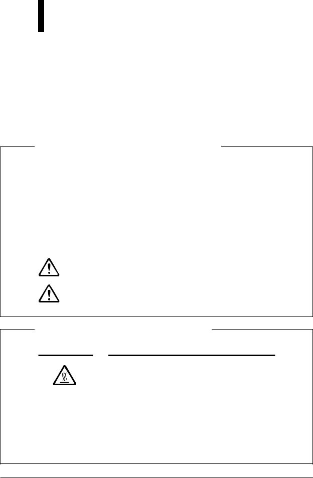
LAYOUT DIAGRAMS
100
643 (Stage area)
250
Center of gravity position
6 x 6 STAGE JAPAN
168 |
305 |
503 (Stage area)
570.4
Eye point |
192.6 |
80 |
|
Center of gravity position
Center of |
|
gravity position |
|
508.5 |
484 |
230 |
230 |
250 |
79 |
262 |
Dimensions are in mm.
This illustration depicts the LV150A microscope configured with the LV-UEPI illuminator, LVTI3 eyepiece tube, LV-LH50PC lamphouse, and 6x6 stage.
6

OPERATING POSTURE
The figure below shows the operating posture that prevents strain on your body.
Choose a workbench and a chair having similar dimensions to those shown in the figure.
The 95th percentile male (Height: 189.5 cm)
of the eyepiece height point) |
seating surface) |
height |
of the |
1269 (The |
(The height |
|
405 |
510
673 |
760 |
Dimensions are in mm.
660
*The height of the eye point is that when one eye-level riser is mounted on the microscope.
*Take at least 610 mm of horizontal clearance for your legs.
The 5th percentile female (Height: 147.5 cm)
of the eyepiece height point) |
seating surface) |
height |
of the |
1244 (The |
(The height |
|
565 |
510
673 |
760 |
135
Dimensions are in mm.
660
* Take at least 610 mm of horizontal clearance for your legs.
7

CONTENTS |
|
|
Warning/Caution Symbols Used in This Manual .............................................. |
1 |
|
Meaning of Symbols Used on the Equipment .................................................. |
2 |
|
WARNING ......................................................................................................... |
2 |
|
CAUTION .......................................................................................................... |
4 |
|
LAYOUT DIAGRAMS ........................................................................................... |
6 |
|
OPERATING POSTURE....................................................................................... |
7 |
|
Names of Each Part ................................................................................... |
10 |
|
1 |
When Configured with the Illuminator LV-UEPI ........................................................... |
10 |
2 |
When Configured with the Illuminator LV-UEPI2 ......................................................... |
12 |
3 |
Rear View ........................................................................................................................ |
14 |
Microscopy ................................................................................................. |
15 |
|
1 |
Bright-Field Microscopy ................................................................................................. |
16 |
2 |
Dark-Field Microscopy ................................................................................................... |
18 |
3 |
Differential Interference Contrast (DIC) Microscopy ..................................................... |
20 |
4 |
Simplified Polarization Microscopy ................................................................................ |
22 |
5 |
Sensitive Polarization Microscopy .................................................................................. |
24 |
6 |
Epi-Fluorescence Microscopy ......................................................................................... |
25 |
Operation of Each Part .............................................................................. |
26 |
|
1 |
Operation of the Illumination .......................................................................................... |
26 |
2 |
Filters ............................................................................................................................... |
26 |
3 |
Coarse/Fine Focus Knobs ................................................................................................ |
27 |
4 |
Eyepiece Tube ................................................................................................................. |
29 |
5 |
Diopter Adjustment ......................................................................................................... |
30 |
6 |
Interpupillary Distance Adjustment ................................................................................ |
30 |
7 |
Field Diaphragm .............................................................................................................. |
31 |
8 |
Aperture Diaphragm ........................................................................................................ |
32 |
9 |
Illumination Selection Lever and Microcopy Selection Knob ........................................ |
33 |
10 |
Stage ................................................................................................................................ |
34 |
11 |
Motorized Nosepiece Operation ...................................................................................... |
35 |
12 |
Polarizer Slider ................................................................................................................ |
36 |
13 |
Lambda Plate Slider (for the LV-UEPI2 only) ................................................................ |
37 |
14 |
Analyzer Slider ................................................................................................................ |
38 |
15 |
DIC Slider ....................................................................................................................... |
39 |
16 |
Filter Cubes for Fluorescence Observation (for the LV-UEPI2 only) ............................. |
40 |
17 |
Excitation Light Balancer (for the LV-UEPI2 Only) ....................................................... |
43 |
8
Assembly .................................................................................................... |
45 |
|
1 |
Attaching the Stage and the Holder ................................................................................. |
47 |
2 |
Assembling the Nosepiece .............................................................................................. |
48 |
3 |
Attaching the Illuminator ................................................................................................ |
50 |
4 |
Attaching the Lamphouse and Replacing the Lamp ....................................................... |
53 |
5 |
Attaching the Fiver Adapter and External Light Source ................................................. |
54 |
6 |
Attaching the Eyepiece Tube ........................................................................................... |
56 |
7 |
Attaching Eyepieces ........................................................................................................ |
56 |
8 |
Attaching Objectives ....................................................................................................... |
56 |
9 |
Attaching Eye Level Riser .............................................................................................. |
57 |
10 |
Attaching Column Riser .................................................................................................. |
57 |
11 |
Connecting the Power Cord ............................................................................................ |
58 |
12 |
Connecting the RS-232C ................................................................................................. |
58 |
13 |
Installing Separately Sold Accessories ............................................................................ |
58 |
14 |
Anti-static Treatment ....................................................................................................... |
58 |
15 |
Countermeasures for Earthquakes ................................................................................... |
59 |
External Communications Control........................................................... |
60 |
|
Troubleshooting......................................................................................... |
66 |
|
1 |
Viewing and control systems ........................................................................................... |
66 |
2 |
Electrical .......................................................................................................................... |
69 |
Care and Maintenance .............................................................................. |
70 |
|
1 |
Cleaning Lenses and Filters ............................................................................................ |
71 |
2 |
Cleaning the Painted, Plastic, and Printed Parts .............................................................. |
71 |
3 |
Storage ............................................................................................................................. |
71 |
4 |
Regular Inspections ......................................................................................................... |
71 |
Specifications ............................................................................................ |
72 |
|
9
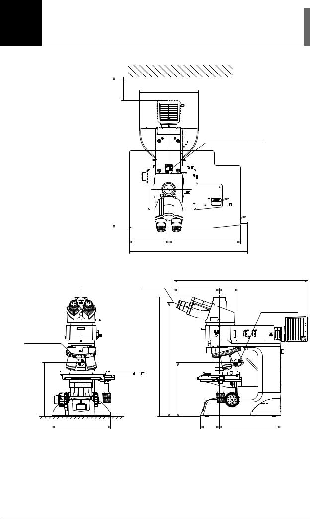
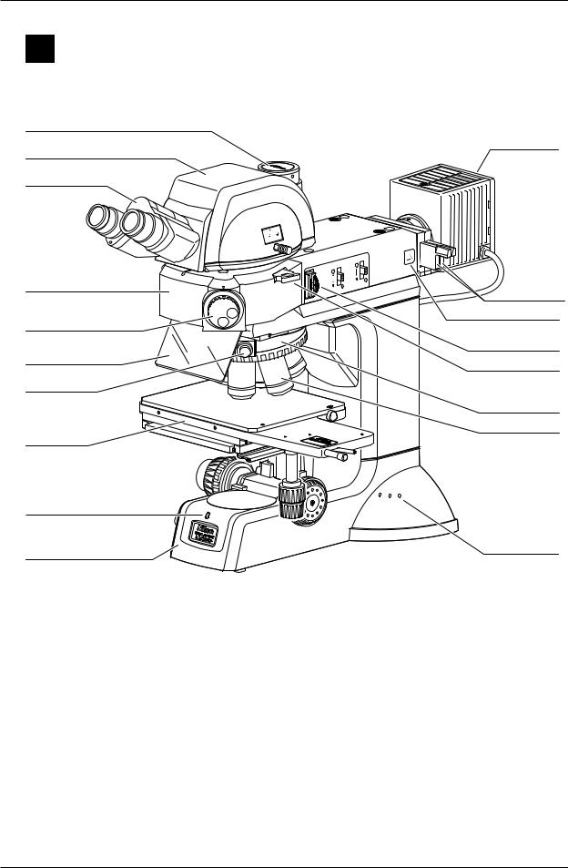
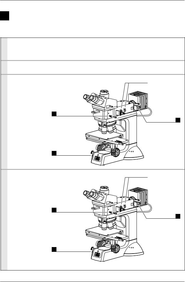
Names of Each Part
1 When Configured with the Illuminator LV-UEPI
 Names of Parts
Vertical tube
Binocular part
Eyepiece tube LV-TI3
Illuminator LV-UEPI
Nosepiece
Objective
Lamphouse
IN |
OUT |
100 |
|
0 |
|
|
0 |
100 |
|
A.STOP
F.STOP
 Filter sliders BF
 DF
DF  “CAUTION for heat” symbol
Polarizer slider *1
Analyzer slider *1
DIC slider *2
Stage
6 x6 JAPANSTAGE
Power indicator
Main body of  Tool holders the microscope
*1: For DIC microscopy or simplified polarization microscopy. *2: For DIC microscopy.
This drawing depicts the ECLIPSE LV150A microscope configured with the LV-UEPI illuminator, LV-TI3 eyepiece tube, LV-LH50PC lamphouse, 6x6 stage, and attachments for DIC microscopy.
10
I. Names of Each Part
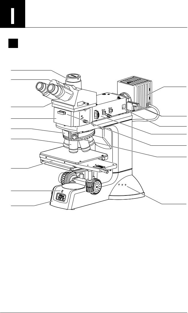
 Names of Operational Parts
Clamp screw for various adapters
Diopter adjustment ring
Eyepiece
Analyzer slider *1
Prism movement knob
Prism  selection knob
DIC slider *2
Optical path selection lever
Field diaphragm open/close lever
Aperture diaphragm open/close lever
IN |
OUT |
100 |
|
0 |
|
|
0 |
100 |
|
A.STOP
F.STOP
BF |
Filter sliders |
 DF
DF
Field diaphragm centering screw
Polarizer slider *1
Bright/dark-field illumination selection lever
Stage coarse/fine movement selection switch
Stage coarse movement lever
Fine focus knob
Coarse focus knob
OBJ. |
OFF |
 Brightness control knob
 Coarse torque adjustment ring
 Nosepiece rotation button (on LV150A only)
6 x6 JAPANSTAGE
Rotates the nosepiece counterclockwise (when seen from above the microscope).
 Nosepiece rotation button (on LV150A only)
Rotates the nosepiece clockwise (when seen from above the microscope).
Stage fine movement knob for Y-axis
Stage fine movement knob for X-axis
Fine focus knob
Coarse focus stopper ring
*1: For DIC microscopy or simplified polarization microscopy. *2: For DIC microscopy.
This drawing depicts the ECLIPSE LV150A microscope configured with the LV-UEPI illuminator, LV-TI3 eyepiece tube, LV-LH50PC lamphouse, 6x6 stage, and attachments for DIC microscopy.
11
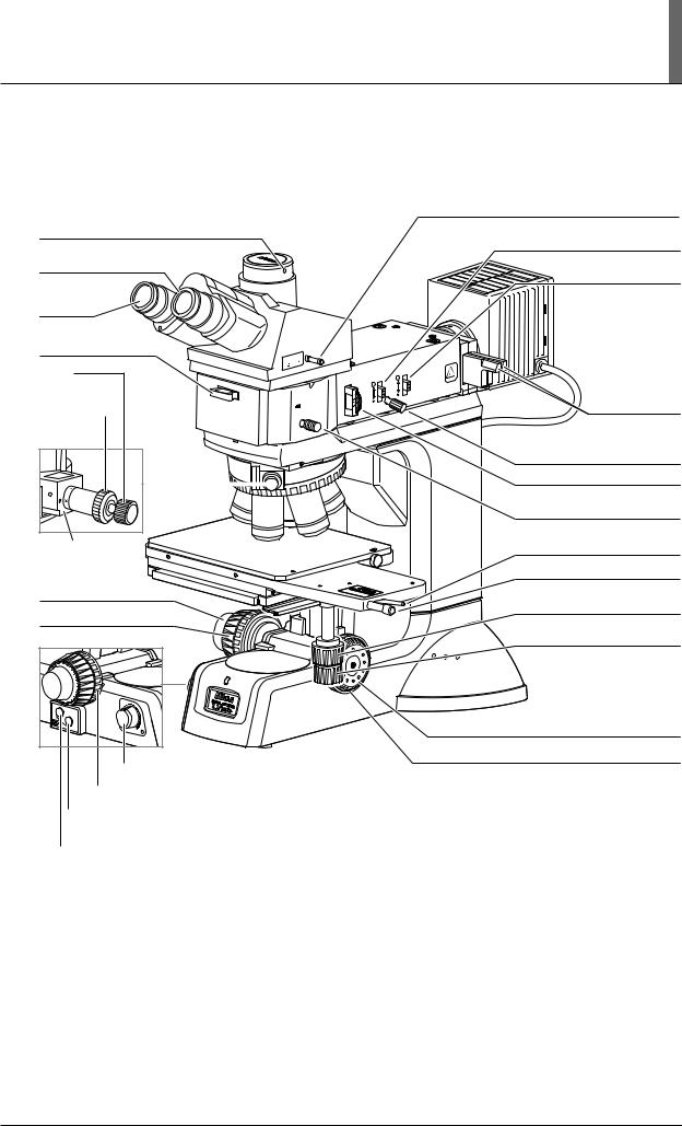
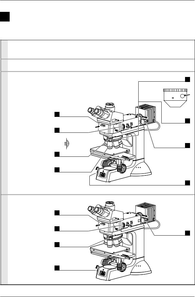
2 When Configured with the Illuminator LV-UEPI2
 Names of Parts
Vertical tube
Eyepiece tube LV-TT2
Binocular part
Illuminator LV-UEPI2
Microscopy selection knob
Ultraviolet light shield
DIC slider *3
Stage
Lamphouse
IN |
OUT |
100 |
|
0 |
|
|
20 |
100 |
|
|
LV-TT2 |
A.STOP
F.STOP
|
BF |
|
Filter sliders |
DF |
|
FL2 |
“CAUTION for heat” symbol |
|
|
|
|
|
|
S |
|
|
FL1 |
|
Polarizer slider *1 |
|
|
|
|
|
|
|
Dummy slider *2 |
|
|
|
Analyzer slider *1 |
|
|
|
Nosepiece |
|
|
|
Objective |
|
|
|
6x6 |
|
|
|
JAPANSTAGE |
Power indicator
Tool holders
Main body of the microscope
*1: For DIC microscopy, simplified polarization microscopy, or sensitive polarization microscopy. *2: Lambda plate slider in case of sensitive polarization microscopy.
*3: For DIC microscopy.
This drawing depicts the ECLIPSE LV150A microscope configured with the LV-UEPI2 illuminator, LV-TT2 eyepiece tube, LV-LH50PC lamphouse, 6x6 stage, and attachments for DIC microscopy.
12

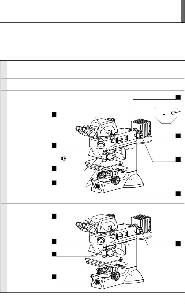
I. Names of Each Part
 Names of Operational Parts
Clamp screw for various adapters
Diopter adjustment ring
Eyepiece
Optical path selection lever
Field diaphragm open/close lever
Aperture diaphragm open/close lever
IN |
OUT |
100 |
|
0 |
|
|
20 |
100 |
|
|
LV-TT2 |
Microscopy selection knob
A.STOP
F.STOP
Prism movement knob
Prism  selection knob
DIC slider *2
|
BF |
DF |
FL2 |
|
S |
|
FL1 |
6x6 JAPANSTAGE
Filter sliders
Aperture diaphragm centering screw (on both sides)
Field diaphragm centering screw (on both sides)
Polarizer slider *1
Dummy slider *2
Analyzer slider *1
Stage coarse/fine movement selection switch
Stage coarse movement lever
Fine focus knob |
Stage fine movement knob |
|
Coarse focus knob |
for Y-axis |
|
Stage fine movement knob |
||
|
||
|
for X-axis |
|
|
Fine focus knob |
|
OBJ. |
|
|
OFF |
|
|
|
Coarse focus stopper ring |
|
|
Brightness control knob |
 Coarse torque adjustment ring
 Nosepiece rotation button (on LV150A only)
Rotates the nosepiece counterclockwise (when seen from above the microscope).
 Nosepiece rotation button (on LV150A only)
Rotates the nosepiece clockwise (when seen from above the microscope).
*1: For DIC microscopy, simplified polarization microscopy, or sensitive polarization microscopy. *2: Lambda plate slider in case of sensitive polarization microscopy.
*3: For DIC microscopy.
This drawing depicts the ECLIPSE LV150A microscope configured with the LV-UEPI2 illuminator, LV-TT2 eyepiece tube, LV-LH50PC lamphouse, 6x6 stage, and attachments for DIC microscopy.
13
I. Names of Each Part
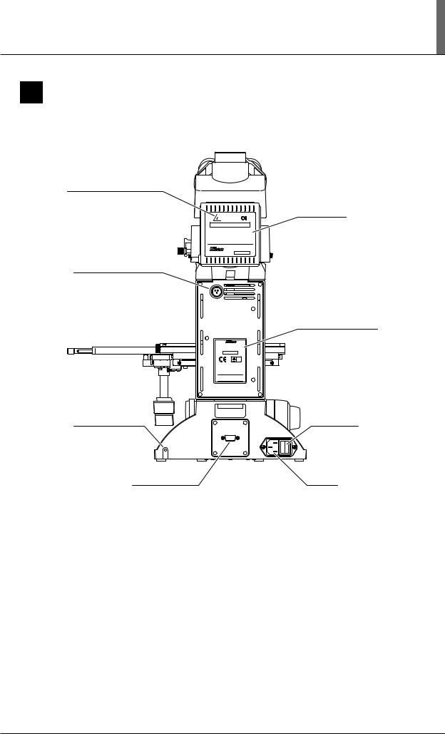
3 Rear View
“CAUTION for heat” symbol
Caution label
CAUTION ! - High Temperature -
1. Do not touch the lamphouse while the lamp is lit. The surface of the lamphouse becomes hot when the lamp is on.
2. Turn off the power and allow the lamp and lamphouse to cool enough before replacing the lamp. Wait for at least 30 minutes after turning off
the lamp
3. Use 12V50W HALOGEN lamp only.
|
HALOGEN 12V50W |
|
LV-LH50PC |
JAPAN |
6 5 2 7 0 1 |
Connector for connecting |
|
the lamphouse |
|
|
LAMP |
|
DC12V 50W |
|
Input voltage indication |
|
ECLIPSE LV150A |
|
100–240V~ 1.2A 50/60Hz |
|
MADE IN JAPAN |
|
5 1 0 0 0 1 |
|
TÜV |
|
including interference that may cause |
|
undesired operation. |
|
This Class A digital apparatus complies with |
|
Canadian ICES-003. |
|
Cet appareil numérique de la classe A est |
|
confirme à la norme NMB-003 du Canada. |
Grounding tap (M4) |
Power switch |
|
RS232C |
RS232C connector |
AC inlet |
This drawing depicts the ECLIPSE LV150A microscope configured with the LV-UEPI illuminator, LV-TI3 eyepiece tube, LV-LH50PC lamphouse, and 6x6 stage.
14

Microscopy
This chapter describes the procedures for each microscopy.
This microscope can be configured with two types of illuminators, LV-UEPI or LV-UEPI2. See the table below for the microscopies available with each illuminator, as well as the optional accessories required for each microscopy.
●If the microscope has not yet been assembled, see “IV. Assembly” on p.45 first.
●See “III. Operation of Each Part” on p.26 for how to operate each part of the microscope.
Microscope |
Procedure |
Illuminators |
Required accessories (optional) |
|
|
|
|
Bright-field |
p.16 to 17 |
LV-UEPI |
– |
microscopy |
|
LV-UEPI2 |
|
|
|
|
|
Dark-field |
p.18 to 19 |
LV-UEPI |
BD objective |
microscopy |
|
LV-UEPI2 |
BD quintuple nosepiece, universal quintuple nosepiece |
|
|
|
or motorized universal quintuple nosepiece* |
|
|
|
(The standard sextuple nosepiece cannot be used |
|
|
|
for dark-field microscopy.) |
|
|
|
|
Differential |
p.20 to 21 |
LV-UEPI |
Polarizer |
interference |
|
LV-UEPI2 |
Analyzer |
contrast (DIC) |
|
|
DIC slider |
microscopy |
|
|
Universal quintuple nosepiece or motorized universal |
|
|
|
quintuple nosepiece* |
|
|
|
Objectives marked “LU” |
|
|
|
(Objectives marked “LU” are suitable for DIC |
|
|
|
microscopy.) |
|
|
|
|
Simplified |
p.22 to 23 |
LV-UEPI |
Polarizer |
polarization |
|
LV-UEPI2 |
Analyzer |
microscopy |
|
|
|
|
|
|
|
Sensitive |
p.24 |
LV-UEPI2 |
Polarizer |
polarization |
|
|
Lambda plate |
microscopy |
|
|
Analyzer |
|
|
|
|
Epi- |
p.25 |
LV-UEPI2 |
Filter cube |
fluorescence |
|
|
(Up to two cubes can be attached.) |
microscopy |
|
|
Fluorescence excitation light balance filter (optional) |
|
|
|
|
* For the LV150A only.
15
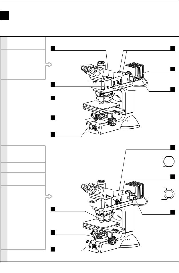
1 Bright-Field Microscopy
 When configured with the LV-UEPI
1.Turn on the power.
2.Set the microscope for bright-field microscopy
If accessories for DIC microscopy (*1 to *3) are in place, pull them out of the optical path.
3.Place the sample on the stage and focus on it.
(p.27)
4.Adjust the diopter. (p.30)
5.Adjust the interpupillary
distance. (p.30)
6.Change the magnification and observe the sample.
Hint:
It may be difficult to focus on a sample with small contrast, such on a polished surface. In a case like this, stop down the field diaphragm so that its image can be seen in the viewfield, and try to focus on the rim of the diaphragm image. When the rim is in focus, the sample is in focus just as well.
1Push in.
Binocular eyepiece: 100% (P.29)
2 |
Push in. |
*1 |
|
||
|
BF (bright-field) (p.33) |
|
|
Select the |
*2 |
3 |
10x objective. |
|
|
On the LV150A, |
|
|
use the nosepiece |
|
|
rotation buttons. (p.35) |
|
4 |
Lower the stage |
|
as far as it will go. |
||
|
Coarse focus knob |
|
|
(p.27) |
|
5 |
Adjust the |
|
brightness. |
|
|
Brightness control knob (p.26)
Select the
1 10x objective.
On the LV150A, use the nosepiece rotation buttons.
(p.35)
Finely adjust 2 the focus.
Coarse/fine focus knob (p.27)
Adjust the
3brightness.
Brightness control knob (p.26)
A STOP
F.STOP
BF
 DF
DF
A.STOP
F.STOP
BF
 DF
DF
Raise the levers. 6
To fully open the field and aperture diaphragms.
(p.31 and p.32)
Push in the NCB11 filter. 7
To compensate color temperature.
(p.26)
|
Adjust the |
|
*3 |
brightness. |
8 |
ND filter (p.26)
 Power switch
Adjust to circumscribe the viewfield. 4
Field diaphragm (p.31)
Image of field diaphragm
Viewfield
Adjust to 70 to 80% of the objective’s N.A. 5
Aperture diaphragm (p.32)
Objective’s pupil
Image of aperture diaphragm
Adjust the brightness. 6
ND filter (p.26)
16
II. Microscopy
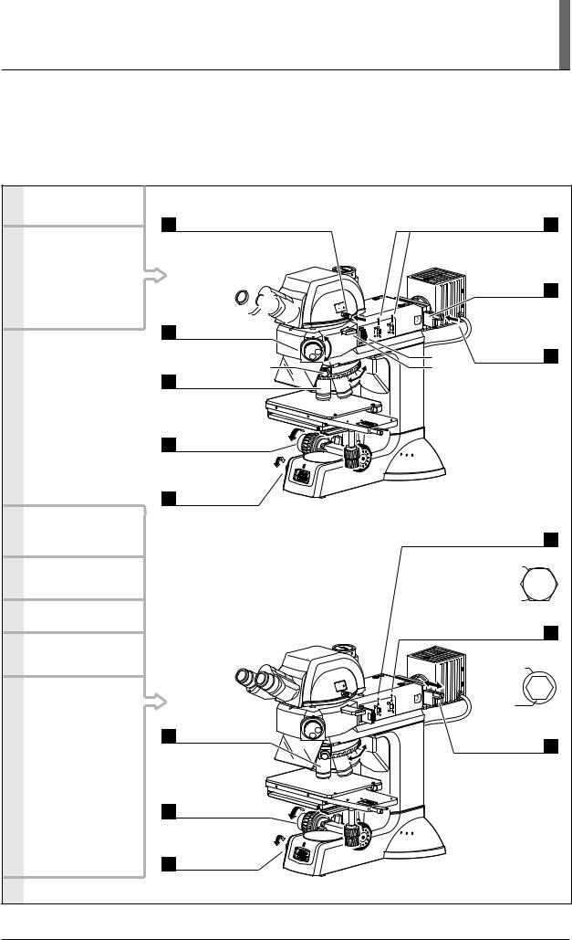
 When configured with the LV-UEPI2
1.Turn on the power.
2.Set the microscope for bright-field microscopy.
If accessories for DIC or polarization microscopy (*1 to *3) are in place, pull them out of the optical path.
3.Place the sample on the stage and focus on it.
(p.27)
4.Adjust the angle of the
binocular part. |
(p.29) |
5.Adjust the diopter. (p.30)
6.Adjust the interpupillary
distance. (p.30)
7.Change the magnification and observe the sample.
Hint:
It may be difficult to focus on a sample with small contrast, such on a polished surface. In a case like this, stop down the field diaphragm so that its image can be seen in the viewfield, and try to focus on the rim of the diaphragm image. When the rim is in focus, the sample is in focus just as well.
1 Push in.
Binocular eyepiece: 100% (P.29)
Turn the 


 microscopy


2 selection knob.
BF (bright-field) (P.33) |
|
BF |
|
DF |
FL2 |
||
|
|
|
FL1 |
Select the |
*2 |
|
|
310x objective.
On the LV150A,
use the nosepiece rotation buttons. (p.35) 
Lower the stage
4as far as it will go.
Coarse focus knob (p.27)
Adjust the
5brightness.
Brightness control knob (p.26)
|
Select the desired |
|
BF |
1 |
DF |
FL2 |
|
magnification. |
|
FL1 |
|
|
On the LV150A, |
|
|
|
use the nosepiece |
|
|
|
rotation switch. |
|
|
|
(p.35) |
|
|
2 |
Finely adjust |
|
|
the focus. |
|
|
|
|
Coarse/fine focus |
|
|
|
knob (p.27) |
|
|
3 |
Adjust the |
|
|
brightness. |
|
|
Brightness control knob (p.26)
A.STOP
F.STOP
A.STOP
F.STOP
Raise the levers. 6
To fully open the field and aperture diaphragms.
(p.31 and p.32)
|
Push in the |
|
|
NCB11 filter. |
7 |
|
To compensate |
|
|
color temperature. |
|
|
(p.26) |
|
|
Adjust the |
|
*3 |
brightness. |
8 |
*1 |
ND filter |
|
|
(p.26) |
|
 Power switch
Adjust to circumscribe the viewfield. 4
Field diaphragm (p.31)
Image of field diaphragm
Viewfield
Adjust to 70 to 80% of the objective’s N.A. 5
Aperture diaphragm (p.32)
Objective’s pupil
Image of aperture diaphragm
Adjust the brightness. 6
ND filter (p.26)
17
2 Dark-Field Microscopy
 When configured with the LV-UEPI
1.Mount BD objectives and a BD quintuple nosepiece, universal quintuple nosepiece, or motorized universal quintuple nosepiece. (p.56 and 49)
The standard sextuple nosepiece cannot be used for dark-field microscopy.
2.Focus on the sample with bright-field microscopy. (p.16)
3.Set the microscope for dark-field microscopy.
The field and aperture diaphragms are fully opened automatically. (However, the lever positions are not changed.)
1Pull out.
DF (dark-field) (P.33)
A.STOP
F.STOP
BF
 DF
DF
Adjust the brightness. 3
ND filter (p.26)
Adjust the 2 brightness.
Brightness control knob (p.26)
4.Return the microscope to bright-field microscopy.
1 Push in.
BF (bright-field) (p.33)
 BF
BF  DF
DF
The field and aperture diaphragms automatically return to what they were before the microscope was set to darkfield microscopy.
A.STOP
F.STOP
Adjust the brightness. 3
ND filter (p.26)
Adjust the
2brightness.
Brightness control knob (p.26)
18
II. Microscopy
 When configured with the LV-UEPI2
1.Mount BD objectives and a BD quintuple nosepiece, universal quintuple nosepiece, or motorized universal quintuple nosepiece. (p.56 and 49)
The standard sextuple nosepiece cannot be used for dark-field microscopy.
2.Focus on the sample with bright-field microscopy. (p.17)
3.Set the microscope for dark-field microscopy.
Turn the microscopy
1selection knob.
DF (dark-field) (p.33)
|
DBF |
FL2DF |
FL2BF |
|
S |
|
FL1 |
The field and aperture diaphragms are fully opened automatically. (However, the lever positions are not changed.)
A.STOP
F.STOP
Adjust the brightness. 3
ND filter (p.26)
Adjust the 2 brightness.
Brightness control knob (p.26)
4.Return the microscope to bright-field microscopy.
Turn the |
|
microscopy |
|
1 selection knob. |
DF |
BF (bright-field) (p.33) |
|
Adjust the 2 brightness.
Brightness control knob (p.26)
BF
FL2
FL1
The field and aperture diaphragms automatically return to what they were before the microscope was set to dark-field microscopy.
A.STOP
F.STOP
Adjust the brightness. 3
ND filter (p.26)
19
3 Differential Interference Contrast (DIC) Microscopy
 When configured with the LV-UEPI
1.Mount objectives marked “LU”, universal quintuple nosepiece or motorized universal quintuple nosepiece, polarizer, analyzer, and DIC slider. (p.36, 38, 39, 49, and 56)
2.Focus on the sample with bright-field microscopy. (p.16)
3.Set the microscope for DIC microscopy.
Information:
The DIC slider can be operated to enable various microscopies, including sensitive DIC.
1 Push in.
Analyzer (p.38)
Push in and align 2 the marks.
Polarizer (p.36)
Crossed Nicols position.
3 Push in.
DIC slider (p.39)
Select the desired 4 magnification.
On the LV150A, use the nosepiece rotation buttons.
(p.35)
BF DF
A STOP F.STOP
Select “A” or “B”. 5
Rotate the inner knob. (p.39)
Match with |
|
the objective |
CF Plan |
indication. |
10X/ 0.30 A |
|
/0 BD DIC |
Select the interference
color. 6
Rotate the top knob. (p.39)
Adjust the brightness. 7
ND filter (p.26)
Adjust the brightness. 8
Brightness control knob (p.26)
4.Return the microscope to the bright-field microscopy.
1Pull out.
Analyzer (p.38)
2Pull out.
Polarizer (p.36)
3Pull out.
DIC slider (p.39)
A STOP
F.STOP
BF
DF
Adjust the brightness. 5
ND filter (p.26)
Adjust the
4brightness.
Brightness control knob (p.26)
20
II. Microscopy
 When configured with the LV-UEPI2
1.Mount objectives marked “LU”, universal quintuple nosepiece, polarizer or motorized quintuple nosepiece, polarizer, analyzer, and DIC slider. (p.36, 38, 39, 49, and 56)
2.Focus on the sample with bright-field microscopy. (p.17)
3.Set the microscope for DIC microscopy.
1Push in.
Analyzer (p.38)
Information:
The DIC slider can be operated to enable various microscopies, including sensitive DIC.
Push in and align 2 the marks.
Polarizer (p.36)
Crossed Nicols position.
3 Push in.
DIC slider (p.39)
Select the desired 4 magnification.
On the LV150A, use the nosepiece rotation buttons.
(p.35)
4.Return the microscope to bright-field microscopy.
1 Pull out.
Analyzer (p.38)
2 Pull out.
Polarizer (p.36)
3 Pull out.
DIC slider (p.39)
DF
A.STOP
F.STOP
BF
FL2
FL1
Select “A” or “B”. 5
Rotate the inner knob. (p.39)
Match with |
|
|
|
|
|
|
|
|
|
|
|
|
|
|
|
the objective |
|
|
|
|
|
CF Plan |
|
|
|
|
|
||||
indication. |
|
|
|
|
|
10X/ 0.30 A |
|||||||||
|
|
|
|
|
|
|
|
/0 BD DIC |
|||||||
|
|
|
|
|
|
|
|
|
|
|
|
|
|
|
|
Select the interference
color. 6
Rotate the top knob. (p.39)
Adjust the brightness. 7
ND filter (p.26)
Adjust the brightness. 8
Brightness control knob (p.26)
|
|
A.STOP |
|
|
F.STOP |
|
BF |
Adjust the |
DF |
FL2 |
|
|
FL1 |
brightness. 5 |
ND filter (p.26)
Adjust the
4brightness.
Brightness control knob (p.26)
21
Loading...