


NIBCO T-413-B, T-413-Y, T-413-W, S-413-B, S-413-Y Installation Manual
...
|
|
|
|
|
|
N I B C O I N C . |
1 5 1 6 M I D D L E B U R Y S T. |
P H O N E : 5 7 4 . 2 9 5 . 3 0 0 0 |
|
|
W O R L D H E A D Q U A R T E R S |
E L K H A R T, I N 4 6 5 1 6 - 4 7 4 0 |
F A X : 5 7 4 . 2 9 5 . 3 3 0 7 |
|
|
|
|
U S A |
W E B : w w w . n i b c o . c o m |
|
|
|
||
|
|
|
|
|
Review Date: 08/01/2017
Original Date: NA
Installation and Maintenance Guidelines for
NIBCO® Bronze Swing Check Valves 1/4” to 3” Class 125, 150, 200 and 300
NIBCO® Performance Bronze® Lead-Free* Swing Check Valves 1/2” to 2”
Figure Numbers
T-413-B,Y,W
S-413-B,Y,W
T-413-Y-LF*
S-413-Y-LF*
T-433-B,Y,W
S-433-B,Y
T-453-B,Y
T-453-B,Y
S-473-B,Y
T-473-B,Y
*Weighted average lead content ≤ 0.25%
CAUTION: Only qualified personnel should undertake the procedures outlined in this document. NIBCO INC., its agents, representatives and employees assumes no liability for the use of these procedures. These procedures are offered as suggestions only.
NIBCO Technical Services • Phone: 1.888.446.4226 • Fax: 1.888.336.4226
1
1.0GENERAL INFORMATION
1.1SCOPE
These instructions are furnished for use in the installation, operation and maintenance of NIBCO 1/4” to 3” Class 125, 150, 200 and 300 bronze swing check valves, with screwed in bonnet, as well as, Lead-Free* Performance Bronze® swing check valves in potable water applications.
1.2GENERAL DATA
A.MANUFACTURER
NIBCO INC.
1516 Middlebury Street Elkhart, IN 46516 Phone: (574) 295-3000
B.FIGURE NUMBERS AND DESCRIPTIONS
Figure |
Description |
Number |
(Swing Check Valves) |
T-413 |
Threaded end, screw in bonnet, W – Buna-N disc (no SWP) |
|
Class 125 B – bronze disc, Y – PTFE disc, |
|
LF – Lead-Free* Performance Bronze® (15 SWP) |
S-413 |
Threaded end, screw in bonnet, W – Buna-N disc (no SWP) |
|
Class 125 B – bronze disc, Y – PTFE disc, |
|
LF – Lead-Free* Performance Bronze® (15 SWP) |
T-433 |
Class 150 threaded end, screw in bonnet, |
|
B – bronze disc, Y – PTFE disc |
S-433 |
Class 150 solder end, screw in bonnet, |
|
B – bronze disc, Y – PTFE disc |
T-453 |
Class 200 threaded end, screw in bonnet, |
|
B – bronze disc, Y – PTFE disc |
T-473 |
Class 300 threaded end, screw in bonnet, |
|
B – bronze disc, Y – PTFE disc |
All threaded end preparations of valves meet American National Pipe Thread (N.P.T.) requirements as per ASME B1.20.1.
All solder end valves meet the requirements of ASME Standard B16.22.
C.IDENTIFICATION PLATES
Identification of the bronze swing check valves is made by checking for the name NIBCO cast onto the side of the valve body. The steam rating and CWP rating is a cross reference with the figure number listed above. These valves are directional. In order for them to function properly, they must be installed with the arrow pointing with the direction of flow. The arrow for direction of flow is cast onto the side of the body. In order to determine the type of seat that is used within the valve, it is necessary to look into its end and determine the seat type. The bronze disc will be
NIBCO Technical Services • Phone: 1.888.446.4226 • Fax: 1.888.336.4226
2
metallic, the PTFE disc is always white in color and the Buna-N disc is black and softer than the other two.
When more detailed information is required, the NIBCO Bronze & Iron Valve catalog should be referred to using the valve figure number as the guide.
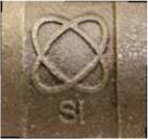
NIBCO® Lead-Free* HydraPure® valves can be identified by the double oval symbol and “Si” – indicative of silicon Performance Bronze® – cast in the body of the valve.
When more detailed information is required, the NIBCO Lead-Free Valve catalog should be referred to using the valve figure number as the guide.
D.SERVICE
When installing valves for service in corrosive media, the NIBCO Chem-Guide may be consulted for specific data or contact can be made with NIBCO Technical Services. It is, however, the obligation of the user to make the ultimate decision of fitness for use.
E.PRESSURE-TEMPERATURE RATINGS
Pressure and temperature ratings may be found in the Engineering section of the latest printing of NIBCO catalog. This information is taken from applicable ASME Standards.
NIBCO Lead-Free* Performance Bronze® maximum pressure-temperature recommendation is 100psi at 300°F and are suitable for low pressure (15psi) steam working pressure service.
F.CODES & REGULATIONS
A valve used under the jurisdiction of the ASME boiler and pressure vessel code, the ANSI code for pressure piping, government or other regulations, is subject to any limitation of that code or regulation and to the applicable ASME Standard.
Lead-Free* Performance Bronze® swing check valves conform to MSS SP-139, NSF/ANSI-61-8 Commercial Hot 180°F (includes Annex F and G), and NSF/ANSI-372. See NIBCO Technical Bulletin NTB-1216 Low Pressure/Low Temperature Valves Lead-Free* Standard Compliance – MSS SP-139 & 145 for further clarification of lead-free standards.
NIBCO Technical Services • Phone: 1.888.446.4226 • Fax: 1.888.336.4226
3
G.PRODUCTION TEST PROCEDURES
Valves are pneumatically shell tested and seat tested at a pressure of 80 psi in accordance with Federal Specifications and MSS SP-80 and/or MSS SP-139 Manufacturers Standardization Society requirements.
H.PRINCIPAL DIMENSIONS
Principal dimensions of the valve are specified in the appropriate catalog.
1.3DETAILED DESCRIPTION
The bronze check valves listed above and covered in these instructions are bronze valves made of ASTM B62 material for Class 125 and 150 valves and from ASTM B61 material for Class 200 and 300 valves.
The Lead-Free* Performance Bronze® swing check valves listed above and covered in these instructions are made from UNS Alloy C87850.
Check valves are used in systems which allow flow to move freely in the direction of the arrow cast onto the side of the valve body, however, should flow reversal occur, the disc in the valve will go to the closed position and not allow flow to reverse. The primary function of a check valve is to prevent backflow.
The disc is centered over the seat in the valve by means of a hanger which is hinged by means of a pin to the main valve body. Therefore, any movement of the disc is in a true arc and the disc will always center itself over the seat in the valve body. On NIBCO bronze check valves, no control of the disc can be affected from the exterior of the valve body. Lever and weights are available only on NIBCO iron check valves.
The body and bonnet are held together by threads of the male and female type; male threads being on the bonnet section and female threads being within the body. There are no gaskets between the body and bonnet to affect seals. This is strictly a metal-to-metal seal as required by standards. This general arrangement is used on all of the listed swing check valves.
2.0INSTALLATION
2.1PRELIMINARY INFORMATION
The bronze check valves may be installed in both horizontal and vertical lines with upward flow or in an intermediate position. They will operate satisfactory in a declining plane no more than 15°. Under no circumstances should the valve be installed in a horizontal line with the bonnet facing in the vertical down position, this will not only trap fluids, but it will not allow the valve to function in the check position.
NIBCO recommends that check valves should not generally be used in close proximity to reciprocating pumps and compressors. The constantly fluctuating pressure curve passes pulsations to the moving parts of the valve and severely shortens the life of the valve due
NIBCO Technical Services • Phone: 1.888.446.4226 • Fax: 1.888.336.4226
4
 Loading...