NIBCO T1810, S1810 Installation Manual

®
Installation, Operating and Maintenance Instructions
Valve Setting
•The valve may be fully closed at any time. However when re-opened, it will stop exactly at the previously set point. Opening movement should cease when resistance is felt. Over tightening is not required and should be avoided.
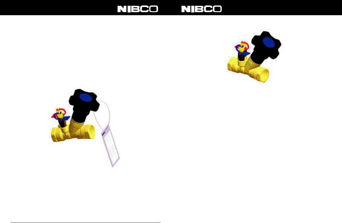
The valve is provided with a data tag that indicates:
•Fig. number of the valve: T1810 or S1810
•Nominal size
•Flow coefficient Cvs
On the tag there is room to write the required initial setting of the valve, indicating either the setting reading, the design flow rate or the pressure signal.
This tag can be fixed to the handwheel with the plastic zip tie provided. The plastic tie is long enough to be used with insulated piping systems and still provide a clear identification of the valve.
Maintenance
The NIBCO® Fixed Orifice Circuit Balancing Valves Fig. T1810 and S1810 do not require any routine maintenance.
NIBCO INC. |
|
1516 MIDDLEBURY STREET |
|
DOMESTIC CUSTOMER SERVICE |
|
TECHNICAL SERVICE |
|
INTERNATIONAL OFFICE |
|
|
|
|
|||||
WORLD HEADQUARTERS |
|
ELKHART, IN 46516-4740 |
|
PHONE: 800.234.0227 |
|
PHONE: 888.446.4226 |
|
PHONE: +1/574.295.3221 |
WEB: www.nibco.com |
|
USA |
|
FAX: 800.234.0557 |
|
FAX: 888.336.4226 |
|
FAX: +1/574.295.3455 |
|
|
|
|
|
|
|
|
|
®
Installation, Operating and Maintenance Instructions Fixed Orifice Circuit Balancing Valve
DZR Brass Fixed Orifice Circuit Balancing Valve
Fixed Orifice Circuit Balancing Valves (FOCBV) provide flow regulation, accurate flow measurement and isolation in a single product. The valve is a precision manufactured product and should be handled, installed and used with care as detailed in these instructions.
Valve Models
•Fig. T1810 has female threaded NPT end connections as ANSI/ASME B1.20.1
•Fig. S1810 has solder end connections as ANSI B16.22
Valves are supplied with P/T ports fitted.
These instructions will also apply to the Low Flow and Ultra Low Flow products. These products are identified by an”L” and “U” marked on the body, respectively.
Limits of Use
The valve rating is shown in the table below and it must be installed in a system where the normal pressure and temperature does not exceed this rating.
The valve is intended for non-shock operating conditions:
Water hammer, impacts, stress loads, corrosive or erosive external environmental elements and the transport of fluids with abrasive properties should be avoided.
Operating Pressure and Temperature
Model |
Non-Shock Pressure at Temperature |
Non-Shock Pressure at Max. |
|
Range |
Temperature |
||
|
|||
T1810 |
300 psi from 15˚F(*) to 160˚F |
150 psi at 260˚F |
|
|
|
|
|
S1810 |
125 psi from 15˚F(*) to 175˚F |
85 psi at 250˚F |
|
|
|
|
(*) = temperatures apply only when glycol additives used.
MV951X000.109
 Loading...