


LD-1000
NIBCO LD-1000, LD-2000, LD-7000, LD-8000, LD-3000 Installation Manual
...
INSTALLATION, OPERATION & MAINTENANCE INSTRUCTIONS
CAUTION: Only qualified personnel should undertake the procedures outlined in this document. NIBCO
INC., its agents, representatives and employees assumes no liability for the use of these procedures. These
procedures are offered as suggestions only.
NIBCO Technical Services • Phone: 1.888.446.4226 • Fax: 1.888.336.4226
1
NIBCO INC.
WORLD HEADQUARTERS
1516 MIDDLEBURY ST.
ELKHART, IN 46516-4740
USA
PHONE: 574.295.3000
FAX: 574.295.3307
WEB: www.nibco.com
Review Date: 06/14/2016
Original Date: 06/01/2009
Installation and Maintenance Guidelines for
NIBCO
®
Butterfly Valves with Rubber Seats
Fire Protection Valves
Commercial Series Valves *UL/ULC/FM Listed
CWP Rating WWP Rating
Figure Numbers
LD-1000/2000/7000/8000 Series
LD/WD-2000/3000/5000 Series
LC/WC-2000 Series
LD/WD-3500 Series* 250 psi/17.2 Bar CWP, 2” – 12”
GD-4700 Series* 300 psi/ 20.7 Bar CWP, 2-1/2” – 8”
175 psi/ 12.1 Bar CWP, 10”
GD-6700 Series** 350 psi / 24 Bar CWP, 2-1/2” – 10”
GD-4800 Series* 300 psi / 20.7 Bar CWP, 2-1/2”-10”
GD-6800 Series* 350 psi / 24 Bar CWP, 2-1/2” – 10”
FC/FD-2000 Series
FC/FD-5000 Series
N-200 Series
** UL Listed only
For any technical inquiries please call NIBCO Technical Services

NIBCO Technical Services • Phone: 1.888.446.4226 • Fax: 1.888.336.4226
2
I. SHIPMENT & STORAGE
NIBCO butterfly valves are individually boxed thru the 12" size. The 14" through 60" butterfly
valves are shipped individually with the faces covered using cardboard or plywood to protect the
flange sealing surfaces.
The disc is shipped in the nearly closed position to protect the sealing edge and prevents the
liner from taking a temporary set. The stem bushings and disc edge have been coated with a
factory-applied lubricant to prolong storage and service life.
Valves may be shipped or stored in any position. Storage should be limited to 10 years indoors
with a temperature range of 40º F to 90º F (4°C to 32°C).
II. BUTTERFLY VALVE INSTALLATION GUIDELINES
NIBCO rubber-lined butterfly valves, depending on size and pressure rating, are designed to
mate with Class 125/150 flange patterns in conformance to ASME B16.1, ASME B16.5, or
ASME B16.47 (Series A) flanges. Cast iron and steel flat-face flanges can be used with all
NIBCO butterfly valves; however, steel raised-face flanges should not be used with cast grey
iron lug-style butterfly valves (NIBCO LC2000 and N200 series).
While flange standards specify flange OD, thickness, bolt size, bolt-circle diameter, and number
of bolts, they may not specify flange opening ID. Care must be used when selecting mating
components for use with NIBCO lug and wafer style butterfly valves. The internal diameter of
flanges, fittings, and pipe must be compatible with the butterfly valve for proper seal-face
integrity and disc operation.
When in the open position, the disc extends outward from the valve body. The internal diameter
of connecting components must be large enough to allow clearance for the disc to fully open.
The disc clearances specified in Table 1 (below) are in accordance with MSS Standard Practice
SP-67 Butterfly Valves, Table A1.
NIBCO 2” thru 48” size butterfly valves have an integral rubber face that seals to the attaching
flange; therefore, a separate gasket is not necessary and should never be used.
The flange inside diameter must not be too large or it will not mate properly with this integral
seal. See Table 1 (below) for minimum and maximum inside diameters of connecting
piping/flanges to assure proper seal-face integrity and full operation of NIBCO butterfly valves.
Verify the inside diameter and clearance dimensions of all components connecting directly to a
butterfly valve
.
NIBCO butterfly valves are bi-directional and may be installed with flow in either direction. These
valve can be installed in any horizontal or vertical position. If a choice of stem positions exists,
the valve should be installed with the stem in the horizontal position; this will minimize seat wear
by distributing the stem and disc weight evenly. Also, if the media is abrasive, the horizontal
stem position is highly preferred.
Butterfly valves should be installed a minimum of six (6) pipe diameters, upstream and
downstream, from other line components. This is not always practical but it is important to design
in as much distance as possible. Interference may occur when valves are installed directly to
the outlet flange of a swing check, silent check, or reducing flange. Check valve and butterfly
valve combinations are very popular; normally a short spool piece is required between the
valves.
When using a valve with gear operator attached, it may be desirable to have the hand wheel
positioned to allow easy access, or for use of an optional adjustable sprocket rim (chain wheel)
for remote operation. Before valve installation, please review Gear Operator Installation and
Hand Wheel Positioning section of this booklet. These instructions illustrate how to orient the
NIBCO Technical Services • Phone: 1.888.446.4226 • Fax: 1.888.336.4226
3
gear operator hand wheel position in relation to the valve body and piping system. Pre-planning
may save from having to remove a newly installed valve and reinstalling in another orientation.
TABLE 1
III. GEAR OPERATOR INSTALLATION AND HANDWHEEL POSITIONING
Piping/Flange Inside Diameter Requirements - Flange, Lug, & Wafer BFVs Only
Valve
Series
LD/WD/LC/WC
1000/2000/3000/5000 Series
LD7000/8000 Series N200 Series
Valve Size
Minimum
Pipe/Flange
ID for Disc
Clearance
Maximum
Pipe/Flange
ID for
Proper Seal
Minimum
Pipe/Flange
ID for Disc
Clearance
Maximum
Pipe/Flange
ID for
Proper Seal
Minimum
Pipe/Flange
ID for Disc
Clearance
Maximum
Pipe/Flange
ID for
Proper Seal
2” 2.00 2.49 1.31 2.43 1.38 2.24
2½” 2.37 2.86 1.89 3.06 1.95 2.74
3” 2.67 3.43 2.64 3.65 2.66 3.33
4” 3.69 4.55 3.67 4.75 3.67 4.55
5” 4.76 5.62 4.44 5.54 4.48 5.50
6” 5.84 6.62 5.96 6.84 5.96 6.66
8” 8.01 8.62 7.85 8.89 7.85 8.61
10” 10.00 10.80 9.73 10.70 9.76 10.75
12” 11.99 13.12 11.71 12.74 11.72 12.79
14” 13.02 14.01 13.02 15.50 — —
16” 15.20 16.30 15.20 17.90 — —
18” 17.09 18.31 17.16 19.67 — —
20” 18.90 20.08 19.10 21.05 — —
24” 23.05 24.71 23.04 25.57 — —
28” — — 27.10 29.31 — —
30” 29.06 30.29 29.08 31.28 — —
32” — — 30.91 33.93 — —
36” 33.59 35.78 33.60 36.77 — —
42” 39.83 42.77 39.87 44.96 — —
48” 44.85 48.27 44.86 51.57 — —
54” — — 50.67 54.25 — —
60” — — 54.93 60.25 — —

NIBCO Technical Services • Phone: 1.888.446.4226 • Fax: 1.888.336.4226
4
TABLE 2
Tools Required
Fire Protection
(UL/FM)
2” – 8” 9/16” Hex Wrench and 1/8” Hex Allen Wrench
10” – 12” 3/4” Hex Wrench and 1/8” Hex Allen Wrench
All Sizes 5/16” Socket Wrench for Stamped Flag
Commercial
2” – 8” 9/16” Hex Wrench
10” – 14” 3/4” Hex Wrench
16” – 18” 1-1/8” Hex Wrench
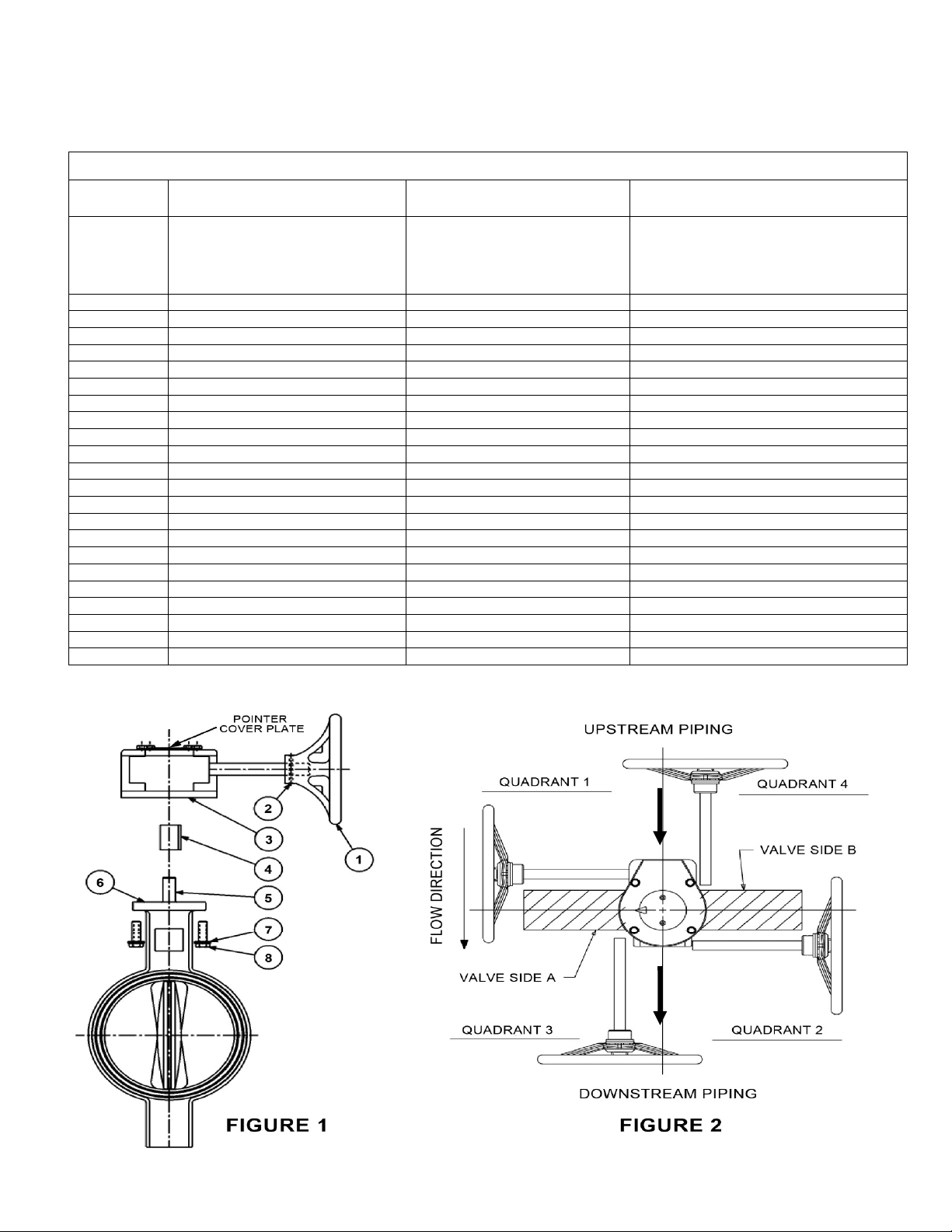
1. Install hand wheel (1) onto gear operator shaft and secure with pin (2). (If not already attached)
See Figure 1.
2. Turn the hand wheel (1) clockwise until in full SHUT position.
3. Remove 2 screws holding pointer cover plate to center of gear operator to expose bore. Retain
pointer cover plate and screws for reinstallation later.
4. Assure valve is in full SHUT position, turn valve stem (5) to close disc if necessary.
5. Assure mounting base of gear operator (3) and the valve top flange (6) are both clean and dry.
6. Determine desired hand wheel position in reference to the piping system and compare with Fig.
2. There are 2 mounting positions for the gear operator onto the valve and the valve can be
mounted in either direction into the piping system. This will allow hand wheel to be positioned in
any of the 4 quadrants as shown in Fig. 2. Note that all Fire Protection and 10” and 12” size
commercial valves allow for hand wheel positioning in quadrants 1 and 2 only.
7a. Gear operators with adapter bushing:
Insert adapter bushing (4) into gear operator (3) bore aligning bushing key with desired
keyway. Keyway selection will determine hand wheel orientation position. (Note that Fire
Protection model adapter bushings differ from illustration and only have 1 keyway position).
Align adapter bushing (4) bore with valve stem (5) and slide gear operator assembly onto valve
stem (5) until seated with valve top flange.
7b. Gear operators without adapter bushing:
Align gear operator (3) bore with valve stem (5) and align with desired keyway. Keyway
selection will determine hand wheel orientation position.
Slide gear operator assembly onto the valve stem (5) until seated with valve top flange.
8. Tightly secure gear operator (3) to valve top flange (6) using supplied* fasteners (7 & 8).
9. Reinstall pointer cover plate onto gear operator removed in Step 3 above. Arrow should be aligned
to indicate SHUT position.
10. Install flag and secure with Allen Screw. (Fire Protection gear operators only).
11. Rotate hand wheel from SHUT to Full OPEN positions several times to assure proper orientation.
See Stop Adjustment Procedure Section of this instruction booklet if stop alignment adjustment is
necessary.
12. Proceed with valve installation into piping system.
* A minimum of two fasteners is required, installed in opposite diagonal corners.
NOTES:
For Fire Protection gear operators, it is critical to use only the key supplied with gear operator
in order to conform to UL, FM and ULC specifications.
Connection of gear operator to valve stem varies depending on gear operator model, size and
style. The adapter bushing and key may be different from Figure 1 illustration shown.

NIBCO Technical Services • Phone: 1.888.446.4226 • Fax: 1.888.336.4226
5
IV. VALVE INSTALLATION PROCEDURE – FLANGE, LUG & WAFER STYLE ONLY
Always position the connecting pipe flanges accurately in the line, allowing sufficient space between
the flanges for the valve. Make sure the pipe flange faces are clean of any foreign material such as
scale, metal shavings or welding slag. Valves should be installed with the disc in the closed position
to prevent damage to sealing surfaces.
NOTE: Fully open and fully shut any butterfly valve before attempting to install it into a system, to
ensure and confirm the valve is operational across its travel range and seating properly in the opened
and shut positions.
1. Carefully ins ert the valve between the pipe flanges. Do not apply any lubricants to the seat faces
as this may damage them.
2. Line up, center and secure the valve between flanges using desired bolts or studs as listed in Table
4. Do not tighten bolts at this time.
3. Carefully open the valve to assure free unobstructed disc movement. Disc interference may result
when valves are installed in pipelines having smaller than normal inside diameters, such as heavy
wall pipe, plastic-lined pipe, as-cast flanges, or reducing flanges. Interference can also occur when
connecting directly to a swing check or silent check. Suitable corrective measures must be taken
to remove these obstructions, such as taper boring the pipe or installing a spacer or spool piece.
4. After proper operation is verified, tighten the bolts to the minimum recommended bolt torques listed
in Table 3, below, using a cross-over pattern as shown in Figure 3. NOTE: When installing any
cartridge liner butterfly valve, i.e. N200 valves or LD 1000/2000 valves NPS 14” and larger,
between two flanges, it is critical that the cartridge liner be evenly compressed from both
sides of the mating flanges (REFER to NIBCO Technical Bulletin NTB-1012-03 for more
details). NIBCO recommends a multi-stepped process utilizing the cross-over pattern be used to
draw the flanges against the liner from both side of the valve at the same rate, ensuring the liner
is compressed evenly. This method differs from the practice used on smaller valves, wherein one
flange side is completely tightened before moving to the opposite side.
5. Pressurize piping to valve and inspect for leakage. If leakage is observed, tighten bolts using
cross-over pattern, increasing torque until leak stops.
DO NOT EXCEED MAXIMUM TORQUES LISTED IN TABLE 3 BELOW.
6. Recommended torques are made without warranty. Installer must verify proper strength bolts for
application. Bolts shall be clean and un-lubricated.
NOTES:
LUG STYLE VALVES – Extra care should be used when installing with raised faced flanges.
Over tightening of bolts can result in broken valve lugs.
Class 250 cast iron and Class 300 steel flanges cannot be used on these valves.
Rubber faced or mechanical flanges are not recommended.
These valves are not recommended for steam service.
Valves should not be assembled to the flanges & then welded into the piping system.
Lever-lock handles are not recommended for use on 8” and larger valves.
Do not install valves with EPDM liner in compressed air lines.
 Loading...