NIBCO F869B User Manual

|
|
|
|
|
|
N I B C O I N C . |
1 5 1 6 M I D D L E B U R Y S T. |
P H O N E : 5 7 4 . 2 9 5 . 3 0 0 0 |
|
|
W O R L D H E A D Q U A R T E R S |
E L K H A R T, I N 4 6 5 1 6 - 4 7 4 0 |
F A X : 5 7 4 . 2 9 5 . 3 3 0 7 |
|
|
|
|
U S A |
W E B : w w w . n i b c o . c o m |
|
|
|
||
|
|
|
|
|
INSTALLATION, OPERATION & MAINTENANCE INSTRUCTIONS
Review Date: 01/18/2012
Original Date: NA
Installation and Maintenance Guidelines for NIBCO® Automatic Steam Stop Check Valves (F-869-B)
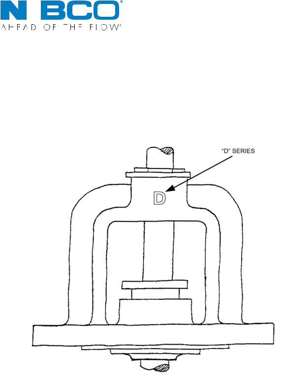
“D” VERSION ONLY
The “D” series valves are identified by the raised letter “D” cast into the bonnet as shown above.
These guidelines apply only to the valves so marked.
CAUTION: Only qualified personnel should undertake the procedures outlined in this document. NIBCO INC., its agents, representatives and employees assumes no liability for the use of these procedures. These procedures are offered as suggestions only.
NIBCO Technical Services • Phone: 1.888.446.4224 • Fax: 1.888.336.4224
1

NIBCO Technical Services • Phone: 1.888.446.4224 • Fax: 1.888.336.4224
2

NIBCO Technical Services • Phone: 1.888.446.4224 • Fax: 1.888.336.4224
3
Guidelines for Disassembly and Cleaning
NIBCO® F-869-B Automatic Steam Stop Check Valves
The NIBCO F-869-B automatic steam stop check valve is the preferred type of valve used on discharge nozzles of steam boilers in multiple boiler installations. The ANSI/ASME Power Piping Code B31.1 makes reference to this in Section 122.1.7A.
Periodically it may become necessary to perform maintenance on these valves to keep them performing at their best. Depending on the water used, conditioners used in the water, as well as other characteristics of the piping system, accumulation of scale and other foreign materials may interfere with good operation of the valve.
After some years of operation, it would be wise to disassemble the valve and inspect for buildup of scale, damage to seating surfaces or any other cause that may interfere with good operation. This can be done during normal shutdown and is not a complicated or expensive job if done properly. Normally, insulation will not have to be removed. Insulation is usually limited to the body portion of the valve. The body should not have to be removed from the system in the majority of cases. In an effort to improve maintenance efficiency, some large multiple boiler installations with four or more boilers keep a spare valve on hand and change one valve every year. This gives the maintenance staff the opportunity to renew one valve each year at their convenience. The following will be a step-by-step guide for this purpose. Also included will be guidelines for renewing the seat and disc surfaces.
CAUTION: A valve shop can do this type of work if they are competent. You may want to check with others in your locale to find out if there is a competent valve shop in your area; but in no case undertake this work yourself or assign this work to others if you have any doubts concerning safety and/or possible damage to the valve or the piping system.
1.Shut down, isolate and drain the portion of the system where the valve is located. Let the system cool off before starting any work on the valve.
2.Mark the body and the bonnet of the valve with chalk or an ink marker in three or four places at the bonnet-body joint to serve as aligning marks during reassembly. Open the valve main operating stem all the way with the handwheel.
3.Remove the valve bonnet-body bolts.
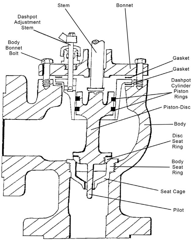
4.Remove the bonnet assembly from body. This must be done very carefully to avoid damaging the main operating stem or the dashpot adjustment stem. The dashpot adjustment stem sticks down into the dashpot without much clearance. Jerking or quick release of the bonnet may result in damage. It may be necessary to loosen the gasket between the bonnet and the dashpot in the body with a putty knife or some similar tool before lifting off the bonnet. Be careful to lift the bonnet straight up until the dashpot adjusting stem clears the dashpot. Take care when setting the bonnet down not to damage or bend the dashpot adjusting valve stem.
Mark the position of the dashpot adjustment assembly on the bonnet if you remove it from the bonnet. You may want to mark the open and closed position of the dashpot adjustment valve permanently by using a small punch mark on the top of the bonnet.
NIBCO Technical Services • Phone: 1.888.446.4224 • Fax: 1.888.336.4224
4
The full operation of this adjustment is only of a turn, 90°, from full open to full close.
5.Remove and discard the gasket between the bonnet and the top lid of the dashpot cylinder. It is not worth the gamble to use an old gasket over again when you consider the valve my leak at the joint afterwards.
6.Mark the dashpot cylinder and body with an ink marker or chalk for alignment when reassembling. The dashpot cylinder may be stuck to the body. Carefully pry the lip of the dashpot cylinder to loosen. Remove the dashpot cylinder. Remove the piston-disc assembly. Lift straight up so as not to bend the disc pilot on the bottom of the disc.
7.Remove and discard the gasket between the body of the valve and underside of the lip on the dashpot cylinder. Carefully clean gasket surfaces.
8.Inspect the valve carefully for evidence of wear, buildup of scale, other foreign matter and any other problem which may cause the valve to operate erratically or incorrectly. It will not be necessary to disassemble the piston-disc, disc seat and pilot to thoroughly examine all components. It will be necessary to examine the piston rings for wear or damage. If they are worn or damaged, they must be replaced. They are not repairable.
Be very careful not to score or mark any of the components while examining them. This is an unhandy procedure so extra care must be taken. It is easy to break or bend the disc pilot on the bottom of the disc if proper care is not taken. The piston rod cannot be removed from the disc or the piston, as it is all one piece.
9.Clean all components as necessary, except the seating surface on the disc and in the body seat. Use light emery cloth of fine sand paper so no large scratches are made on the operating surfaces or sealing surfaces. Check the disc pilot hole in the bottom of the body seat cage.
10.Replace any damaged and non-repairable components. It is always better to change a questionable component then to use it.
11.If the disc and seat are leaking and need to be renewed, cut strips of 120 grit emery paper about 1-1/2” long and 3/8” or 1/2” wide. Using double-backed adhesive tape, stick strips on the seat ring seating surface. The strips should be evenly spaced around the seat. Place the disc in the body and rotate the disc back and forth with very light pressure. The further around you can rotate, the better the surface you will get. Finish up with full rotation. Examine surface periodically, and the new surface will be seen developing. When complete, the new surface on the disc should be all the way across equal to the width of the seat ring seating surface.
12.Repeat this previous step on the seat ring by placing the strips of emery and doublebacked tape on the disc.
13.Clean thoroughly then rotate the disc once or twice lightly in the seat. A shiny line should appear all the way around on the disc and the seat ring. Repeat the above steps until this shiny line can be clearly seen. This line must be unbroken if a good seal is to be achieved. A break in the line is a place the valve will leak. Repeat as needed.
NIBCO Technical Services • Phone: 1.888.446.4224 • Fax: 1.888.336.4224
5
 Loading...