


LRB 20 000
NEWCON OPTIK ™ 2007 Printed in Canada
Operation Manual
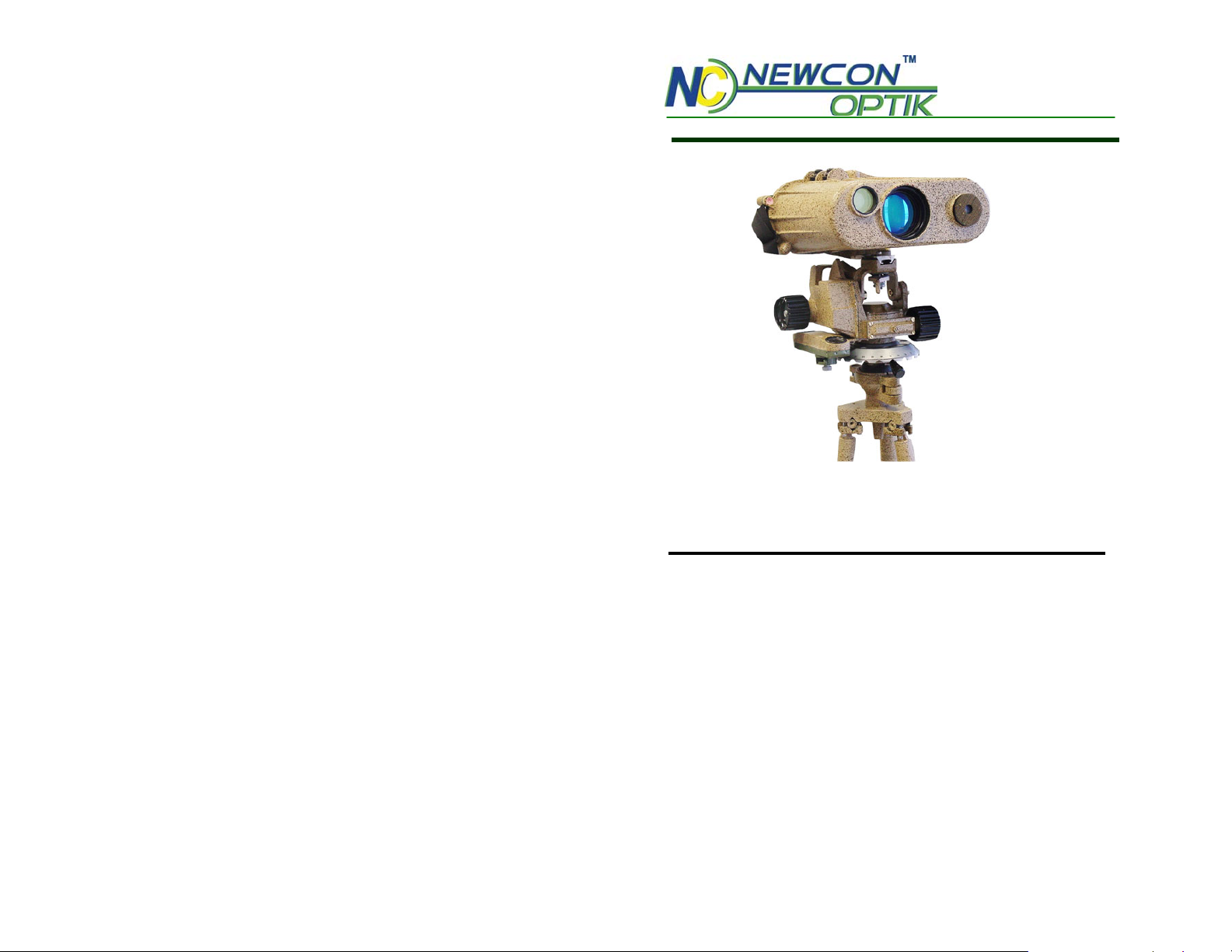
LONG RANGE
LASER RANGE FINDER
LRB 20000
In USA: 2331 Superior Ave. Cleveland, OH 44114
In Canada: 105 Sparks Ave., Toronto, ON M2H 2S5

NOTES:
19. ACCEPTANCE CERTIFICATE
LASER RANGEFINDER LRB20000
Serial Number___________corresponds to all technical specifications
and has passed the quality inspection.
Date of production: _____________
Quality Inspector signature: __________________________
Quality assurance seal

18. CUSTOMER SUPPORT
Should you experience any difficulties with your Newcon
OPTIK product, consult the enclosed manual. If the problem
remains unresolved, contact our customer support department at
1(416) 663-6963 or Toll free at 1-877-368-6666. Our operating
hours are 9am-5pm, Monday - Friday, Standard East Time.
At no time should the equipment be sent back to Newcon
without following the instructions of our technical support
department.
Newcon accepts no responsibility for unauthorized returns.
To locate NEWCON Authorized Dealer call:
Tel: (416) 663-6963 Fax: (416) 663-9065
Email: newconsales@newcon-optik.com
Website: www.newcon-optik.com
The defective products should be shipped to:
From USA: 3310 Prospect Ave. Cleveland, OH 44115
From all other countries: 105 Sparks Ave., Toronto, ON
M2H 2S5, CANADA
IMPORTANT INFORMATION
Read prior to activation
You have just purchased a complicated electronic device, which
emits hazardous invisible laser radiation. To operate it properly,
please read this manual carefully. Here are some common
precautions that must be noted.
• NEVER direct laser radiation at people or animals
• NEVER stare into direct, scattered or reflected laser beam
• NEVER aim the unit at the sun or bright light sources
• NEVER subject the unit to impact while operating or being
transported
• NEVER transport the unit without the case
• NEVER disassemble the unit. This device contains high
voltage components, which may be hazardous for you!
• NEVER reverse polarity of the battery
• ALWAYS keep the unit out of the reach of children
• ALWAYS remove the battery when the device is not in use
for a long period
• ALWAYS store in a warm dry place when the device is not
in use
• Caution - use of controls or adjustments, or performance of
procedures other than those specified herein may result in
hazardous radiation exposure
• Caution - the use of optical instruments such as binoculars,
loupes, mirrors, etc. with this product increases eye hazard

Features of the LRB 20 000 Laser Range Finder
Binocular
• Digital data output
• First or last target indication
• Built-in compass
• Lightweight
• Rugged
• Meet all military specifications
17. WARRANTY
NEWCON OPTIK warrants this product against defects in
material and workmanship for one year from the date of the
original date of consumer's purchase, but no more than 18
months from the date of manufacturing. Longer warranty periods
are available, subject to the terms of specific sales contract.
Should your Newcon product prove defective during this period,
please bring the product securely packaged in its original
container or an equivalent, along with proof of the date of
original purchase, to your Newcon Dealer. Newcon will repair
(or at its option replace), the product or part thereof, which, on
inspection by Newcon, is found to be defective in materials or
workmanship.
What This Warranty Does Not Cover:
NEWCON is not responsible for warranty service should the
product fail to be properly maintained or fail to function properly
as a result of misuse, abuse, improper installation, neglect,
damage caused by disasters such as fire, flood, lightning,
improper electrical current, or service other than by a NEWCON
Authorized Service. Postage, insurance, or shipping costs
incurred in presenting your NEWCON product for warranty
service are your responsibility. Please include a cheque or money
order made out to NEWCON OPTIK for the amount of $15.00 to
cover shipping and handling within North America.

If you use Windows 95, 98 or ME:
- Turn computer on and enter the BIOS SETUP in accordance
with the computer documentation.
- Set the address of LPT port as 378h, and port type as EPP.
Register the new settings.
- After OS on your computer has been loaded, insert the
supplied diskette into the floppy disk drive.
- Run program with the name “BDEPP5.EXE”.
- Perform measurements as described in the manual. The
results will be shown in the communicator program window.
To exit the program, press the space key.
Complete the work in the following order: turn off the
LRB20000A power, take the disk out of the disk drive, and turn
the computer off.
TABLE OF CONTENTS
1. Overview
2. Abbreviations
3. Technical characteristics
4. Supplied accessories
5. Principles of work
6. Safety precautions
7. Preparing for use
8. Operating procedure
9. Serviceability test
10. Maintenance
11. Troubleshooting
12. Long term storage
13. Storage rules
14. Shipment
15. Rechargeable battery
handling
16. Data output to external
equipment
17. Warranty
18. Customer support
19. Acceptance certificate

1. OVERVIEW
RANGEFINDER BINOCULAR LRB 20000 is an advanced
Laser Rangefinder system that provides instant distance
measurements consistently and accurately. The stereoscopic
device provides convenient observation with both eyes.
Therefore, the LRB 20000 eliminates a need for two separate
devices (binocular and rangefinder) combining both
requirements in a single device. It is designated for industrialtechnical purposes, ground surveillance, observation of
individual targets and measurement. It can be used in geological
and engineering survey, repair works, maritime navigation,
meteorology and tourism.
The rangefinder completed with the Angular Mount is designed
for referencing ground location point by the predetermined
landmark coordinates and is capable of:
- measuring horizontal angles and magnetic azimuths:
- measuring vertical angles and angles of elevation;
- determination of target and landmark polar coordinates;
- polar-to-rectangular landmark and target coordinate conversion
and determination of the OP and target coordinates from the
predetermined landmark coordinates.
The supplied software allows data acquisition on IBM PC
compatible computers in DOS/Windows environment. To start
communication with computer, do the following:
If you use Windows NT, 2000, XP, or 2003 Server:
- Turn off the computer.
- Insert the disk which is supplied with the LRB 20,0000A
into the floppy disk drive.
- Turn computer on and enter the BIOS SETUP in accordance
with the computer documentation.
- Set the address of LPT port as 378h, and port type as EPP. In
boot menu, choose the first bootable device as Floppy Drive.
Register the new settings.
- Proceed with loading, choose “5” or just press “Esc” in
options menu. After full loading your computer will work
under MS-DOS.
- In line a:\> type BDEPP5 and press enter to launch the
communication program.
- Perform measurements as described in the manual. The
results will be shown in the communicator program window.

16. DATA OUTPUT TO EXTERNAL EQUIPMENT
The measured data can be exported to a remote computer
through the connector X2.
To export the output data, you must to apply the voltage of 3 to 8
V from the connected computer to the pin 9 of the connector X2.
The amplitude of the output signals will depend on the value of
the supplied voltage.
The measured range information is exported in cycles by a
binary decimal code through four data and three address buses
according to Table 16.1.
The strobe starting the data export appears on pin 8 of the
connector X2 in form of a positive pulse edge.
Table 16.1
Address Data
X2/7 X2/6 X2/5 X2/1, X2/2, X2/3, X2/4
0
0
0
0
1
In each cycle, the digits of the binary decimal data code are
delivered to the pins of connector X2 in accordance with the
schematic circuit diagram of the range finder given in Fig.3.
0
0
1
1
0
0
1
0
1
0
ones of meters (0000 or 0101)
tens of meters (from 0000 to 0101)
hundreds of meters (from 0000 to 0101)
thousands of meters (from 0000 to 0101)
tens of thousands of meters (from 0000 to
0011)
The rangefinder is operable in the temperature range between –
40 and +50 °C, relative air humidity of up to 98% (as taken at
35 °C), air pressure of 61 kPa (460 mm Hg) minimum, and in the
sea mist conditions. It is powered with a rechargeable battery 10
D-0b55С-1. It can be powered with a vehicle electrical system
providing (27±2.7) V, or non- rechargeable battery producing
from 12V to 14.5V or from 22V to 29 V.
Upon receipt of the rangefinder and prior to operation the
user should proceed as follows:
- check to see that the seals on the wooden and metallic
packaged are intact;
- check completeness of the range finder against Section 5 of
this manual;
- check to see that the serial number of the rangefinder is the
same as indicated in Sections 17-19;
- make sure that the optical surfaces are free from grease
stains, dirt, cracks and condensed moisture. Remove dirt and
grease as directed in item 1 of table 11.1;
- inspect the range finder exterior for physical damage (no
cracks, dents, deep rust are admitted);
- check the dehydrator for working condition. If the silica gel
is pink in color, replace it with the new one taken from
individual SPTA set (item 11.6.3);
- place the battery in operation as directed in Section 16 of this
manual (the rechargeable battery is supplied uncharged).

To secure trouble-free operation of the rangefinder:
- be prompt in replacing the rechargeable battery by freshly
charged when the red LED in the left-hand eyepiece of the range
finder starts to illuminate;
- keep the range finder dry at all times especially in the cold
season of the year;
- after exposure to subzero temperatures keep the range finder at
room temperature for at least two hours before unpacking and
then mop up the condensed moisture;
- while operating the range finder at temperatures above 35˚ C
and exposing to direct sunrays, attach cover AEP 42.63.021
taken from individual SPTA set to keep away sunlight.
Moistening the cover with water is permitted to cool off the
range finder.
After replacement of emitter and (or) control circuit board make
entries in Section 4 of this manual as to their new serial numbers
and basic characteristics.
- Charged as described under 15.3;
- Discharged by setting the toggle switches to the
DISCHARGE and MAIN positions until the DISCHARGED
light diode flashes on and off to indicate the discharged
condition. Charge up the operating voltage for 15 hours as
described under 15.3.
15.3.3. The battery that has been stored in the discharged
condition for over 3 months is subject to two processing cycles
before use.
Cycle 1
- Charging for 24 hours with the toggle switches set to the
CHARGE and PREPARATORY positions on the charging
device;
- Discharging with the toggle switches in the DISCHARGE
and PREPARATORY positions, until the LED labelled
DISCHARGED flashes.
Cycle 2
- Charging as directed under 15.3.;
- Discharging with the toggle switches set to the
DISCHARGE and MAIN positions on the charging device,
until the DISCHARGED diode flashes.
If the minimum discharging time is 5 hours, charge the battery
up to the operating voltage as directed in 15.3.
If the discharging time is between 5 and 3.5 hours, subject the
battery to another Cycle 2 as described in 15.3.3, then charge it
up to the operating voltage as described in 15.3.1.
It’s prohibited to use the battery, if the discharging time was
under 3.5 hours.

15. RECHARGEABLE BATTERY HANDLING
15.1. The rechargeable battery is supplied in discharged
condition.
15.2. While handling the battery, be certain to:
- avoid contact with any bare circuit components while
charging the battery;
- strictly comply with the prescribed charging/discharging
procedures.
NEVER:
- dismantle the battery;
- store the battery together with acids, or batteries using acids.
15.3. The battery is subject to charging at an ambient
temperature of (20±5) °C.
To charge the battery, do the following:
- Unscrew the cover of the battery section on the charging
device;
- Place the battery in the section coupling the "+" terminal
with the bottom contact of the section, and screw the cover;
Connect the charging device to the power source using the
appropriate cable (see in Section 11.3).
15.3.1. The battery that has been stored in the discharged
condition for a maximum of 28 days is to be charged for 15
hours. The toggle switches are placed in the CHARGE and
MAIN positions on the charging device.
15.3.2. If the battery has been stored in the discharged condition
for a time between 28 days and 3 months, it should be cycled as
follows:
2. ABBREVIATIONS
The following abbreviations are used herein:
AC ckt – automatic control circuit,
AI – angular mount,
CD – charging device,
DCC – direct current converter,
ER "0" – zero elevation reference,
F ckt – firing circuit,
IDA – information display assembly,
OP – observation post,
PD – protective device,
PhD – photodetector (assembly),
SB – rechargeable battery,
SPTA – spare parts, tools and accessories,
TSGC – time sensitivity gain control,
TIC – time-interval counter
 Loading...