


ProSecure Web/Email
Security Threat Management
Appliance STM150,
STM300, or STM600
Reference Manual
350 East Plumeria Drive
San Jose, CA 95134
USA
January 2011 202-10519-06 1.0

ProSecure Web/Email Security Threat Management (STM) Appliance
© 2009–2011 NETGEAR, Inc. All rights reserved.
No part of this publication may be reproduced, transmitted, transcribed, stored in a retrieval system, or translated into any language in any form or by any means without the written permission of NETGEAR, Inc.
Technical Support
Thank you for choosing NETGEAR. To register your product, get the latest product updates, or get support online, visit us at http://support.netgear.com.
Phone (US & Canada only): 1-888-NETGEAR
Phone (Other Countries): See Support information card.
Product Updates
Product updates are available on the NETGEAR website at http://prosecure.netgear.com or http://kb.netgear.com/app/home.
ProSecure Forum
Go to http://prosecure.netgear.com/community/forum.php for information about the ProSecure forum and to become part of the ProSecure community.
Trademarks
NETGEAR, the NETGEAR logo, ReadyNAS, ProSafe, ProSecure, Smart Wizard, Auto Uplink, X-RAID2, and NeoTV are trademarks or registered trademarks of NETGEAR, Inc. Microsoft, Windows, Windows NT, and Vista are registered trademarks of Microsoft Corporation. Other brand and product names are registered trademarks or trademarks of their respective holders.
Statement of Conditions
To improve internal design, operational function, and/or reliability, NETGEAR reserves the right to make changes to the products described in this document without notice. NETGEAR does not assume any liability that may occur due to the use, or application of, the product(s) or circuit layout(s) described herein.
Revision History
Manual Part |
Manual |
Publication Date |
Description |
Number |
Version |
|
|
|
Number |
|
|
202-10519-06 |
1.0 |
February 2011 |
Made the following changes: |
|
|
|
• Upgraded the book to the new format. |
|
|
|
• Entirely revised Chapter 6, Monitoring System Access and |
|
|
|
Performance, to document the new Logs, Reports, and Alerts |
|
|
|
configuration menus that replaced the old Logs & Report |
|
|
|
configuration menu. |
|
|
|
• Added Appendix A, Report Templates. |
|
|
|
• Separated the traffic logs into email traffic logs and Web traffic |
|
|
|
logs (see Configuring and Activating System, Email, and Syslog |
|
|
|
Logs and Querying Logs). |
|
|
|
• Under the Monitoring main navigation menu, replaced all |
|
|
|
screen shots that showed the old Logs & Reports configuration |
|
|
|
menu with screen shots that show the new Alerts, Logs, and |
|
|
|
Reports configuration menus. |
|
|
|
|
2 |

ProSecure Web/Email Security Threat Management (STM) Appliance
202-10519-06 |
1.0 |
February 2011 |
(continued) |
(continued) |
|
(continued) |
• Revised the Setup Wizard update settings information (see |
|
|
|
Setup Wizard Step 7 of 11: Update Settings), software update |
|
|
|
information (see Updating the Software), and system status |
|
|
|
information (see Viewing System Status). |
|
|
|
|
202-10519-05 |
1.0 |
July 2010 |
Added the following major new features: |
|
|
|
• Network refresh and permanent MAC address bindings (see |
|
|
|
Configuring the Network Refresh and Permanent MAC Address |
|
|
|
Bindings) |
|
|
|
• Setting exceptions for custom groups and custom categories, |
|
|
|
and setting exceptions for file extensions and protocols (see |
|
|
|
Setting Scanning Exclusions and Web Access Exceptions) |
|
|
|
• Creating custom groups (see Creating Custom Groups for Web |
|
|
|
Access Exceptions) |
|
|
|
• Creating custom categories—see Creating Custom Categories |
|
|
|
for Web Access Exceptions) |
|
|
|
• Using the DC Agent (see Understanding the ProSecure DC |
|
|
|
Agent, Requirements for the ProSecure DC Agent Software |
|
|
|
and DC Agent Server, and Downloading ProSecure DC Agent |
|
|
|
Software, and Creating and Deleting DC Agents) |
|
|
|
Also added the following minor features: |
|
|
|
• Requirement to accept terms of service agreement on the |
|
|
|
Real-Time Blacklist screen |
|
|
|
• Capability to set the public host, IP address, and port on the |
|
|
|
Distributed Spam Analysis screen |
|
|
|
• Capability to replace the content of a blocked page with custom |
|
|
|
text |
|
|
|
• Capability to enable and disable SSLv2 |
|
|
|
• Refinements in the active users search methods. |
|
|
|
• Domain information in the output screens that are accessible |
|
|
|
from the Monitoring menu |
|
|
|
• Testing a URL as part of the diagnostics tools |
|
|
|
|
202-10519-01 |
1.1 |
October 2009 |
Index update. |
|
|
|
|
202-10519-01 |
1.0 |
September 2009 |
Initial publication of this reference manual. |
|
|
|
|
| 3

Contents
Chapter 1 Introduction
What Is the ProSecure Web/Email Security Threat Management Appliance STM150, STM300, or STM600?. . . . . . . . . . . . . . . . . . . . . . . . . . . . . . . . . . 8 What Can You Do with an STM? . . . . . . . . . . . . . . . . . . . . . . . . . . . . . . . . . 9 Key Features and Capabilities . . . . . . . . . . . . . . . . . . . . . . . . . . . . . . . . . . . 9 Stream Scanning for Content Filtering . . . . . . . . . . . . . . . . . . . . . . . . . . 10 Autosensing Ethernet Connections with Auto Uplink . . . . . . . . . . . . . . .11 Easy Installation and Management . . . . . . . . . . . . . . . . . . . . . . . . . . . . 11 Maintenance and Support . . . . . . . . . . . . . . . . . . . . . . . . . . . . . . . . . . . 12 STM Model Comparison. . . . . . . . . . . . . . . . . . . . . . . . . . . . . . . . . . . . . 12 Service Registration Card with License Keys. . . . . . . . . . . . . . . . . . . . . . . 12 Package Contents . . . . . . . . . . . . . . . . . . . . . . . . . . . . . . . . . . . . . . . . . . . 13 Hardware Features. . . . . . . . . . . . . . . . . . . . . . . . . . . . . . . . . . . . . . . . . . . 14 Front Panel Ports and LEDs. . . . . . . . . . . . . . . . . . . . . . . . . . . . . . . . . . 14 Rear Panel Features . . . . . . . . . . . . . . . . . . . . . . . . . . . . . . . . . . . . . . . 20 Bottom Panel with Product Label . . . . . . . . . . . . . . . . . . . . . . . . . . . . . . 22 Choosing a Location for the STM . . . . . . . . . . . . . . . . . . . . . . . . . . . . . . . . 23 Using the Rack-Mounting Kit . . . . . . . . . . . . . . . . . . . . . . . . . . . . . . . . . 24
Chapter 2 Using the Setup Wizard to Provision the STM in Your Network
Choosing a Deployment Scenario . . . . . . . . . . . . . . . . . . . . . . . . . . . . . . . 25 Gateway Deployment . . . . . . . . . . . . . . . . . . . . . . . . . . . . . . . . . . . . . . . 25 Server Group . . . . . . . . . . . . . . . . . . . . . . . . . . . . . . . . . . . . . . . . . . . . . 26 Segmented LAN Deployment . . . . . . . . . . . . . . . . . . . . . . . . . . . . . . . . . 27 Understanding the Steps for Initial Connection . . . . . . . . . . . . . . . . . . . . . 27 Qualified Web Browsers . . . . . . . . . . . . . . . . . . . . . . . . . . . . . . . . . . . . . 28 Logging In to the STM . . . . . . . . . . . . . . . . . . . . . . . . . . . . . . . . . . . . . . . . 28 Understanding the Web Management Interface Menu Layout . . . . . . . .30 Using the Setup Wizard to Perform the Initial Configuration . . . . . . . . . . .32 Setup Wizard Step 1 of 10: Introduction. . . . . . . . . . . . . . . . . . . . . . . . . 33 Setup Wizard Step 2 of 11: Networking Settings . . . . . . . . . . . . . . . . . . 33 Setup Wizard Step 3 of 11: Time Zone . . . . . . . . . . . . . . . . . . . . . . . . . 35 Setup Wizard Step 4 of 11: Email Security. . . . . . . . . . . . . . . . . . . . . . . 37 Setup Wizard Step 5 of 11: Web Security . . . . . . . . . . . . . . . . . . . . . . . 39 Setup Wizard Step 6 of 11: Email Notification Server Settings . . . . . . .42 Setup Wizard Step 7 of 11: Update Settings . . . . . . . . . . . . . . . . . . . . . 43 Setup Wizard Step 8 of 11: HTTP Proxy Settings . . . . . . . . . . . . . . . . . 45 Setup Wizard Step 9 of 11: Web Categories . . . . . . . . . . . . . . . . . . . . . 46
Contents | 4

ProSecure Web/Email Security Threat Management (STM) Appliance
Setup Wizard Step 10 of 11: Configuration Summary . . . . . . . . . . . . . .48 Setup Wizard Step 11 of 11: Restarting the System . . . . . . . . . . . . . . .49 Verifying Correct Installation. . . . . . . . . . . . . . . . . . . . . . . . . . . . . . . . . . . .49 Testing Connectivity . . . . . . . . . . . . . . . . . . . . . . . . . . . . . . . . . . . . . . . .49 Testing HTTP Scanning . . . . . . . . . . . . . . . . . . . . . . . . . . . . . . . . . . . . .49 Registering the STM with NETGEAR . . . . . . . . . . . . . . . . . . . . . . . . . . . . .50 What to Do Next . . . . . . . . . . . . . . . . . . . . . . . . . . . . . . . . . . . . . . . . . . . . .51
Chapter 3 Performing Network and System Management
Configuring Network Settings . . . . . . . . . . . . . . . . . . . . . . . . . . . . . . . . . . .52 Configuring Session Limits and Timeouts . . . . . . . . . . . . . . . . . . . . . . . . .56 Configuring the Network Refresh and
Permanent MAC Address Bindings . . . . . . . . . . . . . . . . . . . . . . . . . . . . . .57 Managing Permanent MAC Address Bindings . . . . . . . . . . . . . . . . . . . .59 Configuring the HTTP Proxy Settings. . . . . . . . . . . . . . . . . . . . . . . . . . . . .60 About Users with Administrative and Guest Privileges. . . . . . . . . . . . . . . .61 Changing Administrative Passwords and Timeouts . . . . . . . . . . . . . . . .62 Configuring Remote Management Access . . . . . . . . . . . . . . . . . . . . . . . . .64 Using an SNMP Manager. . . . . . . . . . . . . . . . . . . . . . . . . . . . . . . . . . . . . .65 Supported MIB Browsers . . . . . . . . . . . . . . . . . . . . . . . . . . . . . . . . . . . .67 Managing the Configuration File. . . . . . . . . . . . . . . . . . . . . . . . . . . . . . . . .67 Backing Up Settings . . . . . . . . . . . . . . . . . . . . . . . . . . . . . . . . . . . . . . . .68 Restoring Settings . . . . . . . . . . . . . . . . . . . . . . . . . . . . . . . . . . . . . . . . .69 Reverting to Factory Default Settings . . . . . . . . . . . . . . . . . . . . . . . . . . .70 Updating the Software . . . . . . . . . . . . . . . . . . . . . . . . . . . . . . . . . . . . . . . .71 Scheduling Updates . . . . . . . . . . . . . . . . . . . . . . . . . . . . . . . . . . . . . . . .71 Performing a Manual Update . . . . . . . . . . . . . . . . . . . . . . . . . . . . . . . . .73 Critical Updates That Require a Restart . . . . . . . . . . . . . . . . . . . . . . . . .74 Configuring Date and Time Service . . . . . . . . . . . . . . . . . . . . . . . . . . . . . .74 Managing Digital Certificates . . . . . . . . . . . . . . . . . . . . . . . . . . . . . . . . . . .76 Managing the Certificate for HTTPS Scans . . . . . . . . . . . . . . . . . . . . . .78 Managing Trusted Certificates . . . . . . . . . . . . . . . . . . . . . . . . . . . . . . . .79 Managing Untrusted Certificates . . . . . . . . . . . . . . . . . . . . . . . . . . . . . .80 Managing the Quarantine Settings . . . . . . . . . . . . . . . . . . . . . . . . . . . . . . .81 Managing the STM’s Performance . . . . . . . . . . . . . . . . . . . . . . . . . . . . . . .82
Chapter 4 Content Filtering and Optimizing Scans
About Content Filtering and Scans. . . . . . . . . . . . . . . . . . . . . . . . . . . . . . .84
Default Email and Web Scan Settings . . . . . . . . . . . . . . . . . . . . . . . . . .85
Configuring Email Protection . . . . . . . . . . . . . . . . . . . . . . . . . . . . . . . . . . .87
Customizing Email Protocol Scan Settings. . . . . . . . . . . . . . . . . . . . . . .87
Customizing Email Anti-Virus Settings . . . . . . . . . . . . . . . . . . . . . . . . . .88
Email Content Filtering . . . . . . . . . . . . . . . . . . . . . . . . . . . . . . . . . . . . . .94
Protecting Against Email Spam . . . . . . . . . . . . . . . . . . . . . . . . . . . . . . .97
Configuring Web and Services Protection . . . . . . . . . . . . . . . . . . . . . . . .105
Customizing Web Protocol Scan Settings . . . . . . . . . . . . . . . . . . . . . .105
Configuring Web Malware Scans . . . . . . . . . . . . . . . . . . . . . . . . . . . . .107
Contents | 5

ProSecure Web/Email Security Threat Management (STM) Appliance
Configuring Web Content Filtering . . . . . . . . . . . . . . . . . . . . . . . . . . . . 109 Configuring Web URL Filtering. . . . . . . . . . . . . . . . . . . . . . . . . . . . . . . 116 HTTPS Scan Settings. . . . . . . . . . . . . . . . . . . . . . . . . . . . . . . . . . . . . . 119 Specifying Trusted Hosts . . . . . . . . . . . . . . . . . . . . . . . . . . . . . . . . . . . 124 Configuring FTP Scans . . . . . . . . . . . . . . . . . . . . . . . . . . . . . . . . . . . . 125
Configuring Application Control . . . . . . . . . . . . . . . . . . . . . . . . . . . . . . . . 127 Setting Scanning Exclusions and Web Access Exceptions . . . . . . . . . . . 130 Setting Scanning Exclusions . . . . . . . . . . . . . . . . . . . . . . . . . . . . . . . . 130 Setting Access Exception Rules for Web Access. . . . . . . . . . . . . . . . . 132 Creating Custom Groups for Web Access Exceptions . . . . . . . . . . . . . 139 Creating Custom Categories for Web Access Exceptions . . . . . . . . . . 142
Chapter 5 Managing Users, Groups, and Authentication
About Users, Groups, and Domains. . . . . . . . . . . . . . . . . . . . . . . . . . . . . 147 Configuring Groups . . . . . . . . . . . . . . . . . . . . . . . . . . . . . . . . . . . . . . . . . 148 Creating and Deleting Groups by Name. . . . . . . . . . . . . . . . . . . . . . . . 149 Editing Groups by Name . . . . . . . . . . . . . . . . . . . . . . . . . . . . . . . . . . . 150 Creating and Deleting Groups by IP Address and Subnet . . . . . . . . . . 151 Configuring User Accounts. . . . . . . . . . . . . . . . . . . . . . . . . . . . . . . . . . . . 152 Creating and Deleting User Accounts . . . . . . . . . . . . . . . . . . . . . . . . . 153 Editing User Accounts . . . . . . . . . . . . . . . . . . . . . . . . . . . . . . . . . . . . . 154 Configuring Authentication . . . . . . . . . . . . . . . . . . . . . . . . . . . . . . . . . . . . 154 Understanding the STM’s Authentication Options . . . . . . . . . . . . . . . . 155 Understanding Active Directories and LDAP Configurations . . . . . . . . 157 Creating and Deleting LDAP and Active Directory Domains . . . . . . . . 161 Editing LDAP and Active Directory Domains . . . . . . . . . . . . . . . . . . . . 164 Understanding the ProSecure DC Agent . . . . . . . . . . . . . . . . . . . . . . . 164
Requirements for the ProSecure DC Agent Software and
DC Agent Server . . . . . . . . . . . . . . . . . . . . . . . . . . . . . . . . . . . . . . . . . 165 Downloading ProSecure DC Agent Software, and Creating
and Deleting DC Agents . . . . . . . . . . . . . . . . . . . . . . . . . . . . . . . . . . . . 165 Creating and Deleting RADIUS Domains . . . . . . . . . . . . . . . . . . . . . . . 167 Editing RADIUS Domains and Configuring VLANs . . . . . . . . . . . . . . . 169 Global User Settings . . . . . . . . . . . . . . . . . . . . . . . . . . . . . . . . . . . . . . . . 170 Viewing and Logging Out Active Users . . . . . . . . . . . . . . . . . . . . . . . . . . 172
Chapter 6 Monitoring System Access and Performance
Configuring Logging, Alerts, and Event Notifications . . . . . . . . . . . . . . . . 175 Configuring the Email Notification Server. . . . . . . . . . . . . . . . . . . . . . . 176 Configuring and Activating System, Email, and Syslog Logs . . . . . . . . 177 Configuring Alerts . . . . . . . . . . . . . . . . . . . . . . . . . . . . . . . . . . . . . . . . . 182 Monitoring Real-Time Traffic, Security, Statistics, and Web Usage. . . . . 184 Understanding the Information on the Dashboard Screen . . . . . . . . . . 184 Monitoring Web Usage . . . . . . . . . . . . . . . . . . . . . . . . . . . . . . . . . . . . . 190 Viewing System Status. . . . . . . . . . . . . . . . . . . . . . . . . . . . . . . . . . . . . . . 192 Querying Logs . . . . . . . . . . . . . . . . . . . . . . . . . . . . . . . . . . . . . . . . . . . . . 194 Example: Using Logs to Identify Infected Clients . . . . . . . . . . . . . . . . . 199
6 | Contents

ProSecure Web/Email Security Threat Management (STM) Appliance
Log Management . . . . . . . . . . . . . . . . . . . . . . . . . . . . . . . . . . . . . . . . .199 Viewing, Scheduling, and Generating Reports. . . . . . . . . . . . . . . . . . . . .200 Report Templates . . . . . . . . . . . . . . . . . . . . . . . . . . . . . . . . . . . . . . . . .200 Generating Reports for Downloading . . . . . . . . . . . . . . . . . . . . . . . . . .202 Scheduling Automatic Generation and Emailing of Reports. . . . . . . . .203 Advanced Report Filtering Options. . . . . . . . . . . . . . . . . . . . . . . . . . . .204 Viewing and Managing the Quarantine Files . . . . . . . . . . . . . . . . . . . . . .208 Using Diagnostics Utilities . . . . . . . . . . . . . . . . . . . . . . . . . . . . . . . . . . . .215 Using the Network Diagnostic Tools. . . . . . . . . . . . . . . . . . . . . . . . . . .216 Using the Realtime Traffic Diagnostics Tool. . . . . . . . . . . . . . . . . . . . .217
Gathering Important Log Information and
Generating a Network Statistics Report . . . . . . . . . . . . . . . . . . . . . . . .218 Restarting and Shutting Down the STM . . . . . . . . . . . . . . . . . . . . . . . .219
Chapter 7 Troubleshooting and Using Online Support
Basic Functioning . . . . . . . . . . . . . . . . . . . . . . . . . . . . . . . . . . . . . . . . . . .223 Power LED Not On . . . . . . . . . . . . . . . . . . . . . . . . . . . . . . . . . . . . . . . .223 Test LED or Status LED Never Turns Off. . . . . . . . . . . . . . . . . . . . . . .223 LAN or WAN Port LEDs Not On . . . . . . . . . . . . . . . . . . . . . . . . . . . . . .224 Troubleshooting the Web Management Interface . . . . . . . . . . . . . . . . . .224 When You Enter a URL or IP Address a Time-Out Error Occurs. . . . . . .225 Troubleshooting a TCP/IP Network Using a Ping Utility. . . . . . . . . . . . . .225 Testing the LAN Path to Your STM . . . . . . . . . . . . . . . . . . . . . . . . . . .226 Testing the Path from Your PC to a Remote Device . . . . . . . . . . . . . .226 Restoring the Default Configuration and Password . . . . . . . . . . . . . . . . .227 Problems with Date and Time . . . . . . . . . . . . . . . . . . . . . . . . . . . . . . . . .228 Using Online Support . . . . . . . . . . . . . . . . . . . . . . . . . . . . . . . . . . . . . . . .228 Enabling Remote Troubleshooting . . . . . . . . . . . . . . . . . . . . . . . . . . . .228 Installing Hot Fixes . . . . . . . . . . . . . . . . . . . . . . . . . . . . . . . . . . . . . . . .229 Sending Suspicious Files to NETGEAR for Analysis . . . . . . . . . . . . . .230 Accessing the Knowledge Base and Documentation . . . . . . . . . . . . . .231
Appendix A Report Templates
Appendix B Default Settings and Technical Specifications Appendix C Related Documents
Appendix D Notification of Compliance
Index
Contents | 7

1. Introduction |
1 |
|
|
||
|
|
|
This chapter provides an overview of the features and capabilities of the ProSecure Web/Email Security Threat Management Appliance STM150, STM300, and STM600. It also identifies the physical features of the appliances and the contents of the product packages.
This chapter contains the following sections:
•What Is the ProSecure Web/Email Security Threat Management Appliance STM150, STM300, or STM600? on this page
•What Can You Do with an STM? on page 9
•Key Features and Capabilities on page 9
•Service Registration Card with License Keys on page 12
•Package Contents on page 13
•Hardware Features on page 14
•Choosing a Location for the STM on page 23
What Is the ProSecure Web/Email Security Threat Management Appliance STM150, STM300, or STM600?
The ProSecure Web/Email Security Threat Management Appliance STM150, STM300, or STM600, hereafter referred to as the STM, is an appliance-based, Web and email security solution that protects the network perimeter against Web-borne threats from spyware, viruses, email, and blended threats. Ideally deployed at the gateway, it serves as the network’s first line of defense against all types of threats, and complements firewalls, intrusion detection systems (IDS)/intrusion prevention systems (IPS), dedicated Intranet security products, and endpoint antivirus and antispyware software.
Powered by patent-pending Stream Scanning technology and backed by one of the most comprehensive malware databases in the industry, the STM can detect and stop all known spyware and viruses at the gateway, preventing them from reaching your desktops and servers, where cleanup would be much more difficult.
In addition to scanning HTTP, HTTPS, FTP, SMTP, POP3, and IMAP traffic, the STM protects networks against spam phishing attacks and unwanted Web use. The STM is a plug-and-play device that can be installed and configured within minutes.
Chapter 1. Introduction | 8

ProSecure Web/Email Security Threat Management (STM) Appliance
What Can You Do with an STM?
The STM combines robust protection against malware threats with ease of use and advanced reporting and notification features to help you deploy and manage the device with minimal effort.
Here are some of the things that you can do with the STM:
•Protect the network instantly. The STM is a plug-and-play security solution that can be instantly added to networks without the need for network reconfiguration.
•Scan network traffic for malware. Using the Stream Scanning technology, you can configure the STM to scan HTTP, HTTPS, FTP, SMTP, POP3, and IMAP protocols. Unlike traditional batch-based scan engines that need to cache the entire file before they can scan, this scan engine checks traffic as it enters the network, ensuring unimpeded network performance.
•Set access policies for individual users or groups. You can configure Web and email access policies for individual users and groups based on the STM’s local database, on a group IP address, on a Lightweight Directory Access Protocol (LDAP) domain, group, or user, or on a RADIUS VLAN.
•Receive real-time alerts and generate comprehensive reports. You can configure the STM to send alerts when a malware attack or outbreak is detected on the network. Real-time alerts can be sent by email, allowing you to monitor malware events wherever you are.
By configuring the STM to send malware alerts, you can isolate and clean the infected computer before the malware incident can develop into a full-blown outbreak. The STM also provides comprehensive reports that you can use to analyze network and malware trends.
•Manage through SNMP support. You can enable and configure the STM’s Simple Network Management Protocol (SNMP) settings to receive SNMP traps through a supported management information base (MIB) browser.
•Allow automated component updates. Downloading components regularly is the key to ensuring updated protection against new threats. The STM makes this administrative task easier by supporting automatic malware pattern, program, and engine updates.
Key Features and Capabilities
The STM provides the following key features and capabilities:
•Up to two pairs of 10/100/1000 Mbps Gigabit Ethernet WAN ports (see STM Model Comparison on page 12).
•Scalable support (see STM Model Comparison on page 12) for:
-Up to 600 concurrent users
-Up to 6000 concurrently scanned HTTP sessions
Chapter 1. Introduction | 9

ProSecure Web/Email Security Threat Management (STM) Appliance
-Up to 239 MB/s HTTP throughput
-Up to 960,000 emails per hour SMTP throughput
•Stream Scanning technology that enables scanning of real-time protocols such as HTTP.
•Comprehensive Web and email inbound and outbound security, covering six major network protocols: HTTP, HTTPS, FTP, SMTP, POP3, and IMAP.
•URL content filtering with 64 categories.
•Malware database containing hundreds of thousands of signatures of spyware, viruses, and other malware threats.
•Very frequently updated malware signatures, hourly if required. The STM can automatically check for new malware signatures as frequently as every 15 minutes.
•Multiple antispam technologies to provide extensive protection against unwanted emails.
•Spam and malware quarantine for easy analysis.
•Web application control, including access control for instant messaging, media applications, peer-to-peer applications, and Web-based tools and toolbars.
•User management with LDAP, Active Directory, and RADIUS integration, allowing you to configure access policies per user and per group.
•Easy, Web-based wizard setup for installation and management.
•SNMP-manageable.
•Dedicated management interface. (This feature is model dependent; see STM Model Comparison on page 12.)
•Hardware bypass port to prevent network disruption in case of failure. (This feature is model dependent; see STM Model Comparison on page 12.)
•Front panel LEDs for easy monitoring of status and activity.
•Internal universal switching power supply.
Stream Scanning for Content Filtering
Stream Scanning is based on the simple observation that network traffic travels in streams. The STM scan engine starts receiving and analyzing traffic as the stream enters the network. As soon as a number of bytes are available, scanning starts. The scan engine continues to scan more bytes as they become available, while at the same time another thread starts to deliver the bytes that have been scanned.
This multithreaded approach, in which the receiving, scanning, and delivering processes occur concurrently, ensures that network performance remains unimpeded. The result is file scanning that is up to five times faster than with traditional antivirus solutions—a performance advantage that you will notice.
Stream Scanning also enables organizations to withstand massive spikes in traffic, as in the event of a malware outbreak. The scan engine has the following capabilities:
•Real-time protection. The Stream Scanning technology enables scanning of previously undefended real-time protocols, such as HTTP. Network activities susceptible to latency (for example, Web browsing) are no longer brought to a standstill.
10 | Chapter 1. Introduction
ProSecure Web/Email Security Threat Management (STM) Appliance
•Comprehensive protection. Provides both Web and email security, covering six major network protocols: HTTP, HTTPS, FTP, SMTP, POP3, and IMAP. The STM uses enterprise-class scan engines employing both signature-based and distributed spam analysis to stop both known and unknown threats. The malware database contains hundreds of thousands of signatures of spyware, viruses, and other malware.
•Objectionable traffic protection. The STM prevents objectionable content from reaching your computers. You can control access to the Internet content by screening for Web categories, Web addresses, and Web services. You can log and report attempts to access objectionable Internet sites.
•Automatic signature updates. Malware signatures are updated as frequently as every hour, and the STM can check automatically for new signatures as frequently as every 15 minutes.
Autosensing Ethernet Connections with Auto Uplink
With its internal 10/100/1000 ports, the STM can connect to either a 10 Mbps standard Ethernet network, a 100 Mbps Fast Ethernet network, or a 1000 Mbps Gigabit Ethernet network. The interfaces are autosensing and capable of full-duplex or half-duplex operation.
The STM incorporates Auto UplinkTM technology. Each Ethernet port automatically senses whether the Ethernet cable plugged into the port should have a “normal” connection such as to a PC or an “uplink” connection such as to a switch or hub. That port then configures itself correctly. This feature eliminates the need to think about crossover cables, as Auto Uplink accommodates either type of cable to make the right connection.
Easy Installation and Management
You can install, configure, and operate the STM within minutes after connecting it to the network. The following features simplify installation and management tasks:
•Browser-based management. Browser-based configuration allows you to easily configure the STM from almost any type of operating system, such as Windows, Macintosh, or Linux. A user-friendly Setup Wizard is provided, and online help documentation is built into the browser-based Web Management Interface.
•SNMP. The STM supports SNMP to let you monitor and manage log resources from an SNMP-compliant system manager. The SNMP system configuration lets you change the system variables for MIB2.
•Diagnostic functions. The STM incorporates built-in diagnostic functions such as a ping utility, traceroute utility, DNS lookup utility, and remote restart.
•Remote management. The STM allows you to log in to the Web Management Interface from a remote location on the Internet. For security, you can limit remote management access to a specified remote IP address or range of addresses.
•Visual monitoring. The STM’s front panel LEDs provide an easy way to monitor its status and activity.
Chapter 1. Introduction | 11

ProSecure Web/Email Security Threat Management (STM) Appliance
Maintenance and Support
NETGEAR offers technical support seven days a week, 24 hours a day. Information about support is available on the NETGEAR ProSecure website at http://prosecure.netgear.com/support/index.php.
STM Model Comparison
The following table compares the three STM models to show the differences:
Table 1. Differences between the STM Models
Feature |
STM150 |
STM300 |
STM600 |
|
|
|
|
Performance and Sizing Guidelines |
|
|
|
|
|
|
|
Concurrent users |
Up to 150 |
Up to 300 |
Up to 600 |
|
|
|
|
Web scan throughput |
42 Mbps |
136 Mbps |
307 Mbps |
|
|
|
|
Concurrent scanned HTTP connections |
1500 |
3000 |
6000 |
|
|
|
|
SMTP throughput (emails per hour) |
122,000 |
355,000 |
550,000 |
|
|
|
|
Hardware |
|
|
|
|
|
|
|
Gigabit RJ-45 ports |
Total of 5 ports: |
Total of 3 ports: |
Total of 5 ports: |
|
• 1 uplink |
• 1 pair of ports |
• 2 pairs of portsa |
|
• 4 downlink |
(1 uplink and |
(2 uplink and |
|
|
1 downlink) |
2 downlink) |
|
|
• 1 management |
• 1 management |
|
|
|
|
Gigabit RJ45 port pairs with failure bypass |
0 |
1 pair of ports |
2 pairs of ports |
|
|
|
|
Dedicated management VLAN RJ45 ports |
0 |
1 |
1 |
|
|
|
|
a. The STM600 provides two pairs of ports, allowing for support of two separate networks or subnets with strict traffic separation.
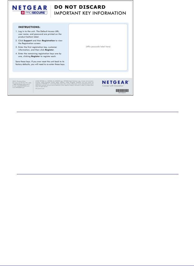
Service Registration Card with License Keys
Be sure to store the license key card that came with your STM in a secure location. You do need these keys to activate your product during the initial setup.
12 | Chapter 1. Introduction
ProSecure Web/Email Security Threat Management (STM) Appliance
Figure 1.
Note: If you reset the STM to the original factory default settings after you have entered the license keys to activate the STM (see Registering the STM with NETGEAR on page 50), the license keys are erased. The license keys and the different types of licenses that are available for the STM are no longer displayed on the Registration screen. However, after you have reconfigured the STM to connect to the Internet and to the NETGEAR registration server, the STM retrieves and restores all registration information based on its MAC address and hardware serial number. You do not need to reenter the license keys and reactivate the STM.
Package Contents
The STM product package contains the following items:
•ProSecure Web/Email Security Threat Management Appliance STM150, STM300, or STM600
•One AC power cable
•Rubber feet (4) with adhesive backing
•One rack-mount kit
•Straight-through Category 5 Ethernet cable
Chapter 1. Introduction | 13
ProSecure Web/Email Security Threat Management (STM) Appliance
•ProSecure™ Web/Email Security Threat Management Applliance STM150, STM300, or STM600 Installation Guide
•Depending on the model purchased, service registration card with one or more license keys
If any of the parts are incorrect, missing, or damaged, contact your NETGEAR dealer. Keep the carton, including the original packing materials, in case you need to return the product for repair.
Hardware Features
The front panel ports and LEDs, rear panel ports, and bottom label of the STM models are described in this section.
Front Panel Ports and LEDs
The front panels of the three STM models provide different components.
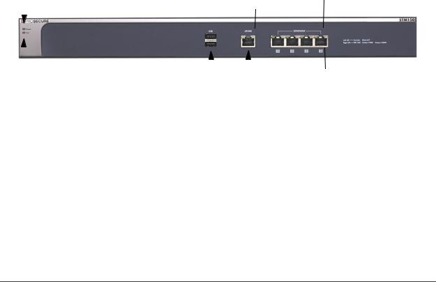
STM150 Front Panel
The following figure shows the front panel ports and status light-emitting diodes (LEDs) of the STM150:
1) Power LED |
|
|
|
5) Downlink LEDs |
||||
|
|
4) Uplink LEDs |
|
|||||
|
|
|||||||
|
|
|
|
|
|
|
|
|
|
|
|
|
|
|
|
|
|
|
|
|
|
|
|
|
|
|
|
|
|
|
|
|
|
|
|
|
|
|
|
|
|
|
|
|
|
|
|
|
|
|
|
|
|
2) Test LED |
3) USB port |
|
5) Downlink ports |
|||||
Figure 2. |
4) Uplink |
port |
|
|
|
|
||
|
|
|
|
|
|
|
||
From left to right, the STM150’s front panel shows the following ports and LEDs:
1.Power LED.
2.Test LED.
3.One nonfunctioning USB port. This port is included for future management enhancements. The port is currently not operable on any STM model.
4.One uplink (WAN) Gigabit Ethernet port with an RJ-45 connector, left LED, and right LED.
5.Four downlink (LAN) Gigabit Ethernet ports with RJ-45 connectors, left LEDs, and right LEDs.
14 | Chapter 1. Introduction

ProSecure Web/Email Security Threat Management (STM) Appliance
Note: All Gigabit Ethernet ports provide switched N-way, automatic speed-negotiating, auto MDI/MDIX technology.
The function of each STM150 LED is described in the following table:
Table 2. LED Descriptions for the STM150
Object |
Activity |
Description |
|
|
|
Power |
On (green) |
Power is supplied to the STM. |
|
|
|
|
Off |
Power is not supplied to the STM. |
|
|
|
Test |
On (amber) during |
The STM is initializing. After approximately 2 minutes, when the STM has |
|
startup |
completed its initialization, the Test LED turns off. If the Test LED remains |
|
|
on, the initialization has failed. |
|
Off |
The system has completed its initialization successfully. The Test LED |
|
|
should be off during normal operation. |
|
|
|
|
Blinking (amber) |
The STM is shutting down. |
|
|
|
|
|
Software is being updated. |
|
|
|
|
|
A hotfix is being installed. |
|
|
|
|
|
One of the three licenses has expired. To stop the Test LED from blinking, |
|
|
renew the license, or click the Stop LED Blinking button on the System |
|
|
Status screen (see Viewing System Status on page 192). |
|
|
|
Uplink (WAN) Port |
|
|
Left LED |
Off |
The WAN port has no physical link, that is, no Ethernet cable is plugged into |
|
|
the STM. |
|
|
|
|
On (green) |
The WAN port has a valid connection with a device that provides an Internet |
|
|
connection. |
|
|
|
|
Blink (green) |
Data is being transmitted or received by the WAN port. |
|
|
|
Right LED |
Off |
The WAN port is operating at 10 Mbps. |
|
|
|
|
On (amber) |
The WAN port is operating at 100 Mbps. |
|
|
|
|
On (green) |
The WAN port is operating at 1000 Mbps. |
|
|
|
Downlink (LAN) Ports |
|
|
Left LED |
Off |
The LAN port has no link. |
|
|
|
|
On (green) |
The LAN port has detected a link with a connected Ethernet device. |
|
|
|
|
Blink (green) |
Data is being transmitted or received by the LAN port. |
|
|
|
Chapter 1. Introduction | 15
ProSecure Web/Email Security Threat Management (STM) Appliance
Table 2. LED Descriptions for the STM150 (Continued)
Object |
Activity |
Description |
|
|
|
Right LED |
Off |
The LAN port is operating at 10 Mbps. |
|
|
|
|
On (amber) |
The LAN port is operating at 100 Mbps. |
|
|
|
|
On (green) |
The LAN port is operating at 1000 Mbps. |
|
|
|
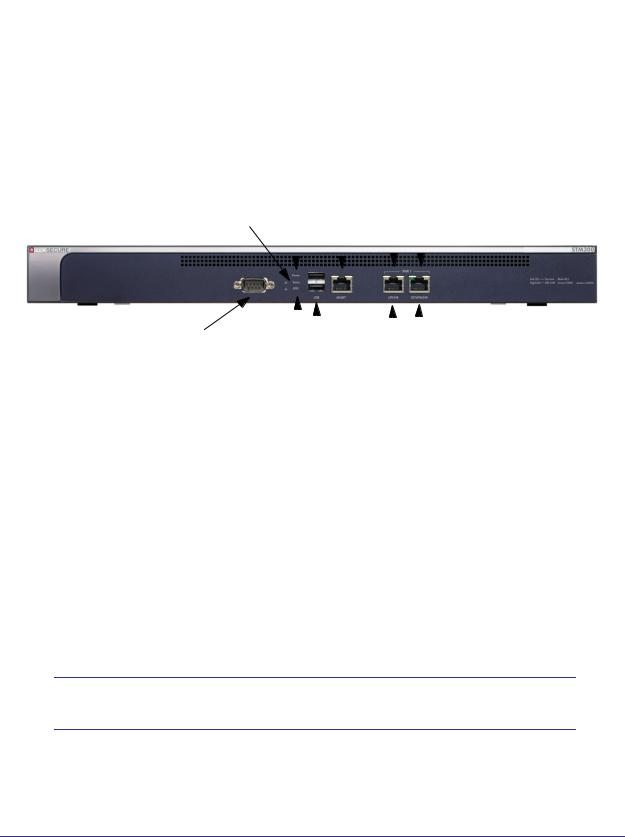
Front Panel STM300
The following figure shows the front panel ports and LEDs of the STM300:
2) Power LED 7) Uplink LEDs
3) Status LED |
6) Mgmt port |
8) Downlink LEDs |
||
|
|
|
|
|
|
|
|
|
|
1) Console port |
|
5) |
|
USB port |
|
8) |
|
Downlink port |
|
|
|
|
|
||||||
|
|||||||||
|
|
|
|
||||||
|
|
|
|
|
|
|
|
||
|
4) HDD LED |
7) Uplink port |
|||||||
Figure 3.
From left to right, the STM300’s front panel shows the following ports and LEDs:
1.Console port. Port for connecting to an optional console terminal. The port has a DB9 male connector. The default baud rate is 9600 K. The pinouts are (2) Tx, (3) Rx, (5) and
(7) Gnd.
2.Power LED.
3.Status LED.
4.Hard drive (HDD) LED.
5.One nonfunctioning USB port. This port is included for future management enhancements. The port is currently not operable on any STM model.
6.Dedicated management (Mgmt) Gigabit Ethernet port with an RJ-45 connector.
7.One uplink (WAN) Gigabit Ethernet port with an RJ-45 connector, left LED, and right LED.
8.One downlink (LAN) Gigabit Ethernet port with RJ-45 connectors, left LED, and right LED.
Note: All Gigabit Ethernet ports provide switched N-way, automatic speed-negotiating, auto MDI/MDIX technology.
16 | Chapter 1. Introduction

ProSecure Web/Email Security Threat Management (STM) Appliance
The function of each STM300 LED is described in the following table:
Table 3. LED Descriptions for the STM300
Object |
Activity |
Description |
|
|
|
Power |
On (green) |
Power is supplied to the STM. |
|
|
|
|
Off |
Power is not supplied to the STM. |
|
|
|
Status |
On (amber) during |
The STM is initializing. After approximately 2 minutes, when the STM has |
|
startup |
completed its initialization, the Status LED turns off. If the Status LED |
|
|
remains on, the initialization has failed. |
|
Off |
The system has completed its initialization successfully. The Status LED |
|
|
should be off during normal operation. |
|
|
|
|
Blinking (amber) |
The STM is shutting down. |
|
|
|
|
|
Software is being updated. |
|
|
|
|
|
A hotfix is being installed. |
|
|
|
|
|
One of the three licenses has expired. To stop the Status LED from blinking, |
|
|
renew the license, or click the Stop LED Blinking button on the System |
|
|
Status screen (see Viewing System Status on page 192). |
|
|
|
HDD |
On (Green) |
Information is being written to the hard drive. |
|
|
|
|
Off |
No hard drive activity. |
|
|
|
Uplink (WAN) Port |
|
|
|
|
|
Left LED |
Off |
The WAN port has no physical link, that is, no Ethernet cable is plugged into |
|
|
the STM. |
|
|
|
|
On (green) |
The WAN port has a valid connection with a device that provides an Internet |
|
|
connection. |
|
Blink (green) |
Data is being transmitted or received by the WAN port. |
|
|
|
Right LED |
Off |
The WAN port is operating at 10 Mbps. |
|
|
|
|
On (green) |
The WAN port is operating at 100 Mbps. |
|
|
|
|
On (amber) |
The WAN port is operating at 1000 Mbps. |
|
|
|
Downlink (LAN) Ports |
|
|
|
|
|
Left LED |
Off |
The LAN port has no link. |
|
|
|
|
On (green) |
The LAN port has detected a link with a connected Ethernet device. |
|
|
|
|
Blink (green) |
Data is being transmitted or received by the LAN port. |
|
|
|
Right LED |
Off |
The LAN port is operating at 10 Mbps. |
|
|
|
|
On (green) |
The LAN port is operating at 100 Mbps. |
|
|
|
|
On (amber) |
The LAN port is operating at 1000 Mbps. |
|
|
|
Chapter 1. Introduction | 17
ProSecure Web/Email Security Threat Management (STM) Appliance
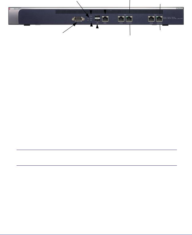
Front Panel STM600
The following figure shows the front panel ports and LEDs of the STM600:
2) Power LED |
7) Pair 1 LEDs |
||||||||
3) Status LED |
6) Mgmt port |
|
|
8) Pair 2 LEDs |
|||||
|
|
|
|
|
|
|
|
|
|
|
|
|
|
|
|
|
|
|
|
|
|
|
|
|
|
|
|
|
|
|
|
|
|
|
|
|
|
|
|
|
|
|
|
|
|
|
|
|
|
|
|
|
|
|
|
|
|
|
|
|
|
|
|
|
|
|
|
|
|
|
|
|
|
|
|
|
|
|
|
|
|
1) Console port |
|
5) |
|
USB port |
|
|
|
8) Pair |
|
2 ports |
|||
|
|
|
|
|
|
||||||||
|
|
|
1 ports |
||||||||||
|
|
|
|
|
|
|
|
|
|
||||
|
4) HDD LED |
7) Pair |
|
|
|
|
|
||||||
Figure 4.
From left to right, the STM600’s front panel shows the following ports and LEDs:
1.Console port. Port for connecting to an optional console terminal. The ports has a DB9 male connector. The default baud rate is 9600 K. The pinouts are (2) Tx, (3) Rx, (5) and
(7) Gnd.
2.Power LED.
3.Status LED.
4.Hard drive (HDD) LED.
5.One nonfunctioning USB port. This port is included for future management enhancements. The port is currently not operable on any STM model.
6.Dedicated management (Mgmt) Gigabit Ethernet port with an RJ-45 connector.
7.Pair 1 uplink (WAN) and downlink (LAN) Gigabit Ethernet ports with RJ-45 connectors, left LEDs, and right LEDs.
8.Pair 2 uplink (WAN) and downlink (LAN) Gigabit Ethernet ports with RJ-45 connectors, left LEDs, and right LEDs.
Note: All Gigabit Ethernet ports provide switched N-way, automatic speed-negotiating, auto MDI/MDIX technology.
18 | Chapter 1. Introduction

ProSecure Web/Email Security Threat Management (STM) Appliance
The function of each STM600 LED is described in the following table:
Table 4. LED Descriptions for the STM600
Object |
Activity |
Description |
|
|
|
Power |
On (green) |
Power is supplied to the STM. |
|
|
|
|
Off |
Power is not supplied to the STM. |
|
|
|
Status |
On (amber) during |
The STM is initializing. After approximately 2 minutes, when the STM has |
|
startup |
completed its initialization, the Status LED turns off. If the Status LED |
|
|
remains on, the initialization has failed. |
|
Off |
The system has completed its initialization successfully. The Status LED |
|
|
should be off during normal operation. |
|
|
|
|
Blinking (amber) |
The STM is shutting down. |
|
|
|
|
|
Software is being updated. |
|
|
|
|
|
A hotfix is being installed. |
|
|
|
|
|
One of the three licenses has expired. To stop the Status LED from blinking, |
|
|
renew the license, or click the Stop LED Blinking button on the System |
|
|
Status screen (see Viewing System Status on page 192). |
|
|
|
HDD |
On (green) |
Information is being written to the hard drive. |
|
|
|
|
Off |
No hard drive activity. |
|
|
|
Uplink (WAN) Port |
|
|
|
|
|
Left LED |
Off |
The WAN port has no physical link, that is, no Ethernet cable is plugged into |
|
|
the STM. |
|
|
|
|
On (green) |
The WAN port has a valid connection with a device that provides an Internet |
|
|
connection. |
|
Blink (green) |
Data is being transmitted or received by the WAN port. |
|
|
|
Right LED |
Off |
The WAN port is operating at 10 Mbps. |
|
|
|
|
On (green) |
The WAN port is operating at 100 Mbps. |
|
|
|
|
On (amber) |
The WAN port is operating at 1000 Mbps. |
|
|
|
Downlink (LAN) Ports |
|
|
|
|
|
Left LED |
Off |
The LAN port has no link. |
|
|
|
|
On (green) |
The LAN port has detected a link with a connected Ethernet device. |
|
|
|
|
Blink (green) |
Data is being transmitted or received by the LAN port. |
|
|
|
Right LED |
Off |
The LAN port is operating at 10 Mbps. |
|
|
|
|
On (green) |
The LAN port is operating at 100 Mbps. |
|
|
|
|
On (amber) |
The LAN port is operating at 1000 Mbps. |
|
|
|
Chapter 1. Introduction | 19

ProSecure Web/Email Security Threat Management (STM) Appliance
Rear Panel Features
The rear panel of the STM150 differs from the rear panels of the STM300 and STM600.
Rear Panel STM150
The following figure shows the rear panel components of the STM150:
|
|
|
|
4) Reset button |
|
|
|
|
|
|
|
1) Console port |
2) Lock |
|
|||
|
|
|
|
|
5) AC power socket |
|
|
|
3) Power button |
||
Figure 5.
From left to right, the STM150’s rear panel components are:
1.Console port. Port for connecting to an optional console terminal. The port has a DB9 male connector. The default baud rate is 9600 K. The pinouts are (2) Tx, (3) Rx, (5) and
(7) Gnd.
2.Kensington lock. Attach an optional Kensington lock to prevent unauthorized removal of the STM150.
3.Power button. Press to restart the STM150. Restarting does not reset the STM150 to its factory defaults.
4.Reset button. Using a sharp object, press and hold this button for about 10 seconds until the front panel Test LED flashes and the STM150 returns to factory default settings.
Note: If you reset the STM150, all configuration settings are lost and the default passwords are restored.
5. AC power socket. Attach the power cord to this socket.
20 | Chapter 1. Introduction
ProSecure Web/Email Security Threat Management (STM) Appliance
Rear Panel STM300 and STM600
The rear panels of the STM300 and STM600 are identical.
The following figure shows the rear panel components of the STM300 and STM600:
1) Power switch
2) AC power socket
Figure 6.
From left to right, the STM300’s and STM600’s rear panel components (excluding the four fan air outlets) are:
1.Power switch. Switch to turn the STM300 or STM600 on or off. Restarting does not reset the STM300 or STM600 to its factory defaults.
Note: The STM300 and STM600 do not provide a Reset button. For information about how to reset the STM300 or STM600 to factory default settings using the Web Management Interface, see
Reverting to Factory Default Settings on page 70.
2. AC power socket. Attach the power cord to this socket.
Chapter 1. Introduction | 21

ProSecure Web/Email Security Threat Management (STM) Appliance
Bottom Panel with Product Label
The product label on the bottom of the STM’s enclosure displays the STM’s default IP address, default user name, and default password, as well as regulatory compliance, input power, and other information.
STM150 Product Label
Figure 7.
STM300 Product Label
Figure 8.
22 | Chapter 1. Introduction

ProSecure Web/Email Security Threat Management (STM) Appliance
STM600 Product Label
Figure 9.
Choosing a Location for the STM
The STM is suitable for use in an office environment where it can be freestanding (on its runner feet) or mounted into a standard 19-inch equipment rack. Alternatively, you can rack-mount the STM in a wiring closet or equipment room. A mounting kit, containing two mounting brackets and four screws, is provided in the STM package.
Consider the following when deciding where to position the STM:
•The unit is accessible and cables can be connected easily.
•Cabling is away from sources of electrical noise. These include lift shafts, microwave ovens, and air-conditioning units.
•Water or moisture cannot enter the case of the unit.
•Airflow around the unit and through the vents in the side of the case is not restricted. Provide a minimum of 25 mm or 1 inch clearance.
•The air is as free of dust as possible.
•Temperature operating limits are not likely to be exceeded. Install the unit in a clean, air-conditioned environment. For information about the recommended operating temperatures for the STM, see Appendix B, Default Settings and Technical Specifications.
Chapter 1. Introduction | 23
ProSecure Web/Email Security Threat Management (STM) Appliance
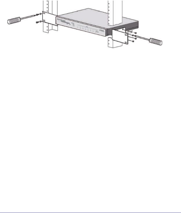
Using the Rack-Mounting Kit
Use the mounting kit for the STM to install the appliance in a rack. (A mounting kit is provided in the product package for the STM.) The mounting brackets that are supplied with the STM are usually installed before the unit is shipped out. If the brackets are not yet installed, attach them using the supplied hardware.
Figure 10.
Before mounting the STM in a rack, verify that:
•You have the correct screws (supplied with the installation kit).
•The rack onto which you will mount the STM is suitably located.
24 | Chapter 1. Introduction

2. Using the Setup Wizard to Provision the |
2 |
STM in Your Network |
This chapter describes provisioning the STM in your network. This chapter contains the following sections:
•Choosing a Deployment Scenario on this page
•Understanding the Steps for Initial Connection on page 27
•Logging In to the STM on page 28
•Using the Setup Wizard to Perform the Initial Configuration on page 32
•Verifying Correct Installation on page 49
•Registering the STM with NETGEAR on page 50
•What to Do Next on page 51
Choosing a Deployment Scenario
The STM is an inline transparent bridge appliance that can easily be deployed to any point on the network without the need for network reconfiguration or additional hardware.
The following are the most common deployment scenarios for the STM. Depending on your network environment and the areas that you want to protect, you can choose one or a combination of the deployment scenarios that are described in the following sections:
•Gateway Deployment on this page
•Server Group on page 26
•Segmented LAN Deployment on page 27
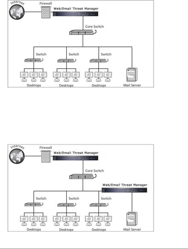
Gateway Deployment
In a typical gateway deployment scenario, a single STM appliance is installed at the gateway—between the firewall and the LAN core switch—to protect the network against all malware threats entering and leaving the gateway. Installing the STM behind the firewall protects it from denial of service (DoS) attacks.
Chapter 2. Using the Setup Wizard to Provision the STM in Your Network | 25
ProSecure Web/Email Security Threat Management (STM) Appliance
The following figure shows a typical gateway deployment scenario:
Figure 11.
Server Group
In a server group deployment, one STM appliance is installed at the gateway and another in front of the server group to help protect the email server from threats from internal as well as external clients. This type of deployment splits the network load and provides the email server with dedicated protection against malware threats, including email-borne viruses and spam. The following figure shows a typical server group deployment scenario:
Figure 12.
26 | Chapter 2. Using the Setup Wizard to Provision the STM in Your Network
ProSecure Web/Email Security Threat Management (STM) Appliance
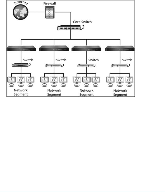
Segmented LAN Deployment
In a segmented LAN deployment, one STM appliance is installed in front of each network segment. VLAN traffic can pass through the STM and can be scanned by the STM. This type of deployment splits the network load and protects network segments from malware threats coming in through the gateway or originating from other segments. The following figure shows a typical segmented LAN deployment scenario:
Figure 13.
Understanding the Steps for Initial Connection
Generally, five steps are required to complete the basic and security configuration of your STM:
1.Connect the STM physically to your network. Connect the cables and restart your network according to the instructions in the installation guide. See the ProSecure™ Web/Email Security Threat Management Appliance STM150, STM300, or STM600 Installation Guide for complete steps. A PDF of the Installation Guide is on the NETGEAR ProSecure™ website at http://prosecure.netgear.com/resources/document-library.php.
2.Log in to the STM. After logging in, you are ready to set up and configure your STM. See
Logging In to the STM on page 28.
3.Use the Setup Wizard to configure basic connections and security. During this phase, you connect the STM to your network. See Using the Setup Wizard to Perform the Initial Configuration on page 32.
Chapter 2. Using the Setup Wizard to Provision the STM in Your Network | 27
ProSecure Web/Email Security Threat Management (STM) Appliance
4.Verify the installation. See Verifying Correct Installation on page 49.
5.Register the STM. See Registering the STM with NETGEAR on page 50.
Each of these tasks is described separately in this chapter.
Qualified Web Browsers
To configure the STM, you need to use a Web browser such as Microsoft Internet Explorer 5.1 or later, Mozilla Firefox l.x or later, or Apple Safari 1.2 or later with JavaScript, cookies, and SSL enabled.
Although these Web browsers are qualified for use with the STM’s Web Management Interface, SSL VPN users should choose a browser that supports JavaScript, Java, cookies, SSL, and ActiveX to take advantage of the full suite of applications. Note that Java is required only for the SSL VPN portal, not for the Web Management Interface.
Logging In to the STM
To connect to the STM, your computer needs to be configured to obtain an IP address automatically from the STM via DHCP. For instructions on how to configure your computer for DHCP, see the document that you can access from Preparing Your Network in Appendix C.
To connect and log in to the STM:
1.Start any of the qualified browsers, as explained in Qualified Web Browsers on this page.
2.Enter https://192.168.1.201 in the address field.
https://192.168.1.201
Figure 14.
Note: The STM factory default IP address is 192.168.1.201. If you change the IP address, you need to use the IP address that you assigned to the STM to log in to the STM.
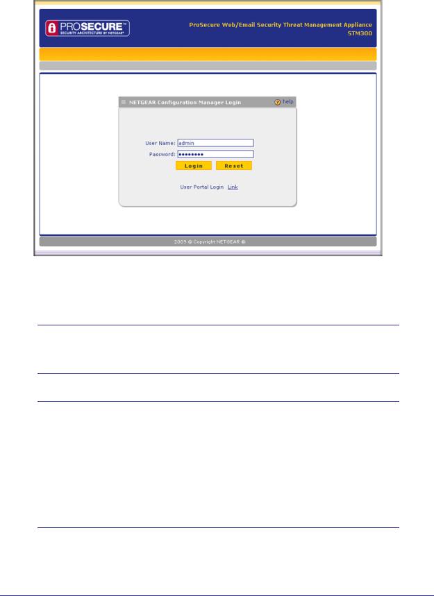
The NETGEAR Configuration Manager Login screen displays in the browser (see the following figure, which shows the STM300).
28 | Chapter 2. Using the Setup Wizard to Provision the STM in Your Network
ProSecure Web/Email Security Threat Management (STM) Appliance
Figure 15.
3.In the User Name field, type admin. Use lowercase letters.
4.In the Password field, type password. Here, too, use lowercase letters.
Note: The STM user name and password are not the same as any user name or password you might use to log in to your Internet connection.
Note: The first time that you remotely connect to the STM with a browser via an SSL VPN connection, you might get a warning message regarding the SSL certificate. If you are using a Windows computer with Internet Explorer 5.5 or later, simply click Yes to accept the certificate. Other browsers provide you with similar options to accept and install the SSL certificate.
If you connect to the STM through the User Portal Login screen (see Figure 88 on page 156), you can import the STM’s root certificate by clicking the link at the bottom of the screen.
Chapter 2. Using the Setup Wizard to Provision the STM in Your Network | 29
ProSecure Web/Email Security Threat Management (STM) Appliance
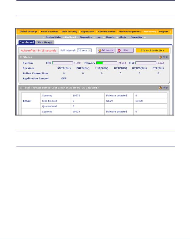
5.Click Login. The Web Management Interface displays, showing the Dashboard screen (see the following figure, which shows only the top part of the screen). For information about this screen, see Understanding the Information on the Dashboard Screen on page 184.
Note: During the initial setup, the Setup Wizard displays when you first log in; afterward the login takes you to the Dashboard screen.
Figure 16.
Note: After 5 minutes of inactivity (the default login time-out), you are automatically logged out.
Understanding the Web Management Interface Menu Layout
The following figure shows the menu at the top of the STM300’s Web Management Interface. The Web Management Interface layouts of the STM150 and STM600 are identical to the STM300.
30 | Chapter 2. Using the Setup Wizard to Provision the STM in Your Network
 Loading...