


S350 Series 8-Port Gigabit Ethernet
Smart Managed Pro Switch
User Manual
Models
GS308T
GS310TP
January 2019 202-11890-01
350 East Plumeria Drive
San Jose, CA 95134
USA

S350 Series 8-Port Gigabit Ethernet Smart Managed Pro Switch Models GS308T and GS310TP
Support
Thank you for purchasing this NETGEAR product. You can visit https://www.netgear.com/support/ to register your product, get help, access the latest downloads and user manuals, and join our community. We recommend that you use only official NETGEAR support resources
Compliance and Conformity
For regulatory compliance information including the EU Declaration of Conformity, visit https://www.netgear.com/about/regulatory/.
See the regulatory compliance document before connecting the power supply.
Do not use this device outdoors. If you connect cables or devices that are outdoors to this device, see http://kb.netgear.com/000057103 for safety and warranty information.
Trademarks
© NETGEAR, Inc., NETGEAR, and the NETGEAR Logo are trademarks of NETGEAR, Inc. Any non-NETGEAR trademarks are used for reference purposes only.
Revision History
Publication Part Number |
Publish Date |
Comments |
|
|
|
202-11890-01 |
January 2019 |
First publication |
|
|
|
2

Contents
Chapter 1 Get Started
Switch Management Interface Overview . . . . . . . . . . . . . . . . . . . . . . . . . . . . . . . 11 Change the Default IP Address of the Switch . . . . . . . . . . . . . . . . . . . . . . . . . . . . 11 Discover a Switch in a Network With a DHCP Server . . . . . . . . . . . . . . . . . . . . . 12 Discover a Switch in a Network Without a DHCP Server . . . . . . . . . . . . . . . . . . 13 Configure the Network Settings on Your Computer . . . . . . . . . . . . . . . . . . . . . . 14 Use the NETGEAR Switch Discovery Tool to Access the Switch . . . . . . . . . . . . . 17 Use the NETGEAR Insight Mobile App to Discover the Switch . . . . . . . . . . . . . . 18 About the User Interfaces . . . . . . . . . . . . . . . . . . . . . . . . . . . . . . . . . . . . . . . . . . . . 18
Software Requirements to Use the Local Browser Interface . . . . . . . . . . . . . 19 Supported Web Browsers . . . . . . . . . . . . . . . . . . . . . . . . . . . . . . . . . . . . . . . . . . 19 Access the Local Browser Interface . . . . . . . . . . . . . . . . . . . . . . . . . . . . . . . . . . . . 19 Navigation Tabs, Configuration Menus, and Page Menu. . . . . . . . . . . . . . . . . 21 Configuration and Status Options . . . . . . . . . . . . . . . . . . . . . . . . . . . . . . . . . . . 22 Buttons in the Local Browser Interface . . . . . . . . . . . . . . . . . . . . . . . . . . . . . . . 22 User-Defined Fields . . . . . . . . . . . . . . . . . . . . . . . . . . . . . . . . . . . . . . . . . . . . . . . 23 Change the Language of the Local Browser Interface. . . . . . . . . . . . . . . . . . . . . 23 Use the Device View of the Local Browser Interface. . . . . . . . . . . . . . . . . . . . . . 24 Power LED in the Device View . . . . . . . . . . . . . . . . . . . . . . . . . . . . . . . . . . . . . . 25 PoE Max LED in the Device View (Model GS310TP) . . . . . . . . . . . . . . . . . . . 25 Interface Naming Conventions . . . . . . . . . . . . . . . . . . . . . . . . . . . . . . . . . . . . . . . . 26 Configure Interface Settings . . . . . . . . . . . . . . . . . . . . . . . . . . . . . . . . . . . . . . . . . . 26 Context-Sensitive Help and Access to the Support WebSite . . . . . . . . . . . . . . . 29 Access the User Guide Online . . . . . . . . . . . . . . . . . . . . . . . . . . . . . . . . . . . . . . . . . 30 Register Your Product. . . . . . . . . . . . . . . . . . . . . . . . . . . . . . . . . . . . . . . . . . . . . . . . 31
Chapter 2 Configure System Information
View and Configure the Switch Management Settings . . . . . . . . . . . . . . . . . . . . 33 View or Define System Information. . . . . . . . . . . . . . . . . . . . . . . . . . . . . . . . . . 33 View the System CPU Status. . . . . . . . . . . . . . . . . . . . . . . . . . . . . . . . . . . . . . . . 36 Configure the IP Network and VLAN Settings for the
Local Browser Interface . . . . . . . . . . . . . . . . . . . . . . . . . . . . . . . . . . . . . . . . . . . . 38 Configure the Time Settings . . . . . . . . . . . . . . . . . . . . . . . . . . . . . . . . . . . . . . . . 40 Configure Denial of Service Settings. . . . . . . . . . . . . . . . . . . . . . . . . . . . . . . . . 54 Configure DNS Settings . . . . . . . . . . . . . . . . . . . . . . . . . . . . . . . . . . . . . . . . . . . . 57 Configure Green Ethernet Settings . . . . . . . . . . . . . . . . . . . . . . . . . . . . . . . . . . 61
Use the Device View . . . . . . . . . . . . . . . . . . . . . . . . . . . . . . . . . . . . . . . . . . . . . . . . . 64 Configure PoE . . . . . . . . . . . . . . . . . . . . . . . . . . . . . . . . . . . . . . . . . . . . . . . . . . . . . . 64 Configure the Global PoE Settings . . . . . . . . . . . . . . . . . . . . . . . . . . . . . . . . . . . 64
3

S350 Series 8-Port Gigabit Ethernet Smart Managed Pro Switch Models GS308T and GS310TP
Configure the PoE Port Settings. . . . . . . . . . . . . . . . . . . . . . . . . . . . . . . . . . . . . 65 Configure SNMP . . . . . . . . . . . . . . . . . . . . . . . . . . . . . . . . . . . . . . . . . . . . . . . . . . . . 69 Configure the SNMPv1/v2 Community . . . . . . . . . . . . . . . . . . . . . . . . . . . . . . 69 Configure SNMPv1/v2 Trap Settings . . . . . . . . . . . . . . . . . . . . . . . . . . . . . . . . 71 Configure SNMPv1/v2 Trap Flags . . . . . . . . . . . . . . . . . . . . . . . . . . . . . . . . . . . 74 View the Supported MIBs . . . . . . . . . . . . . . . . . . . . . . . . . . . . . . . . . . . . . . . . . . 75 Configure SNMP V3 Users. . . . . . . . . . . . . . . . . . . . . . . . . . . . . . . . . . . . . . . . . . 76 Configure LLDP . . . . . . . . . . . . . . . . . . . . . . . . . . . . . . . . . . . . . . . . . . . . . . . . . . . . . 77 Configure LLDP Global Settings . . . . . . . . . . . . . . . . . . . . . . . . . . . . . . . . . . . . . 77 Configure LLDP Port Settings. . . . . . . . . . . . . . . . . . . . . . . . . . . . . . . . . . . . . . . 79 View the LLDP-MED Network Policy . . . . . . . . . . . . . . . . . . . . . . . . . . . . . . . . 80 Configure LLDP-MED Port Settings . . . . . . . . . . . . . . . . . . . . . . . . . . . . . . . . . 82 View the Local Information Advertised Through LLDP . . . . . . . . . . . . . . . . . . 83 View LLDP Neighbors Information . . . . . . . . . . . . . . . . . . . . . . . . . . . . . . . . . . . 85 Configure DHCP Snooping. . . . . . . . . . . . . . . . . . . . . . . . . . . . . . . . . . . . . . . . . . . . 88 Configure the Global DHCP Snooping Settings . . . . . . . . . . . . . . . . . . . . . . . . 89 Enable DHCP for All Interfaces in a VLAN . . . . . . . . . . . . . . . . . . . . . . . . . . . . . 90 Configure DHCP Snooping Interface Settings . . . . . . . . . . . . . . . . . . . . . . . . . 90 Configure Static DHCP Bindings. . . . . . . . . . . . . . . . . . . . . . . . . . . . . . . . . . . . . 92 Configure DHCP Snooping Persistent Settings . . . . . . . . . . . . . . . . . . . . . . . . 93 View or Clear DHCP Snooping Statistics . . . . . . . . . . . . . . . . . . . . . . . . . . . . . . 94 Set Up PoE Timer Schedules . . . . . . . . . . . . . . . . . . . . . . . . . . . . . . . . . . . . . . . . . . 95 Create a PoE Timer Schedule . . . . . . . . . . . . . . . . . . . . . . . . . . . . . . . . . . . . . . . 95 Specify the Settings for an Absolute PoE Timer Schedule . . . . . . . . . . . . . . . 96 Specify the Settings for a Recurring PoE Timer Schedule . . . . . . . . . . . . . . . 97 Change the Settings for a Recurring PoE Timer Schedule Entry . . . . . . . . . . 99 Delete a PoE Timer Schedule Entry . . . . . . . . . . . . . . . . . . . . . . . . . . . . . . . . . 100 Delete a PoE Timer Schedule. . . . . . . . . . . . . . . . . . . . . . . . . . . . . . . . . . . . . . . 101
Chapter 3 Configure Switching
Configure the Port Settings and Maximum Frame Size. . . . . . . . . . . . . . . . . . . 103
Configure Link Aggregation Groups . . . . . . . . . . . . . . . . . . . . . . . . . . . . . . . . . . . 106
Configure LAG Settings . . . . . . . . . . . . . . . . . . . . . . . . . . . . . . . . . . . . . . . . . . . 106
Configure LAG Membership . . . . . . . . . . . . . . . . . . . . . . . . . . . . . . . . . . . . . . . 108
Set the LACP System Priority . . . . . . . . . . . . . . . . . . . . . . . . . . . . . . . . . . . . . . 109
Set the LACP Port Priority Settings . . . . . . . . . . . . . . . . . . . . . . . . . . . . . . . . . 110
Configure VLANs . . . . . . . . . . . . . . . . . . . . . . . . . . . . . . . . . . . . . . . . . . . . . . . . . . . 111
Configure VLAN Settings. . . . . . . . . . . . . . . . . . . . . . . . . . . . . . . . . . . . . . . . . . 112
Configure VLAN Membership . . . . . . . . . . . . . . . . . . . . . . . . . . . . . . . . . . . . . . 115
View the VLAN Status . . . . . . . . . . . . . . . . . . . . . . . . . . . . . . . . . . . . . . . . . . . . 117
Configure Port PVID Settings . . . . . . . . . . . . . . . . . . . . . . . . . . . . . . . . . . . . . . 118
Configure a MAC-Based VLAN . . . . . . . . . . . . . . . . . . . . . . . . . . . . . . . . . . . . . 120
Configure Protocol-Based VLAN Groups . . . . . . . . . . . . . . . . . . . . . . . . . . . . 122
Configure Protocol-Based VLAN Group Membership. . . . . . . . . . . . . . . . . . 123
Configure a Voice VLAN . . . . . . . . . . . . . . . . . . . . . . . . . . . . . . . . . . . . . . . . . . . . . 124
Configure Auto-VoIP . . . . . . . . . . . . . . . . . . . . . . . . . . . . . . . . . . . . . . . . . . . . . . . 126
Configure Protocol-Based Port Settings for VoIP . . . . . . . . . . . . . . . . . . . . . 126
4

S350 Series 8-Port Gigabit Ethernet Smart Managed Pro Switch Models GS308T and GS310TP
Configure Auto-VoIP OUI-Based Properties . . . . . . . . . . . . . . . . . . . . . . . . . 127 Configure the OUI-Based Port Settings . . . . . . . . . . . . . . . . . . . . . . . . . . . . . 128 Manage the OUI Table . . . . . . . . . . . . . . . . . . . . . . . . . . . . . . . . . . . . . . . . . . . . 129 Display the Auto-VoIP Status . . . . . . . . . . . . . . . . . . . . . . . . . . . . . . . . . . . . . . 131 Configure Spanning Tree Protocol. . . . . . . . . . . . . . . . . . . . . . . . . . . . . . . . . . . . . 132 Configure STP Settings . . . . . . . . . . . . . . . . . . . . . . . . . . . . . . . . . . . . . . . . . . . 133 Configure CST Settings . . . . . . . . . . . . . . . . . . . . . . . . . . . . . . . . . . . . . . . . . . . 135 Configure CST Port Settings . . . . . . . . . . . . . . . . . . . . . . . . . . . . . . . . . . . . . . . 136 View the CST Port Status. . . . . . . . . . . . . . . . . . . . . . . . . . . . . . . . . . . . . . . . . . 138 View Rapid STP Information . . . . . . . . . . . . . . . . . . . . . . . . . . . . . . . . . . . . . . . 140 Manage MST Settings . . . . . . . . . . . . . . . . . . . . . . . . . . . . . . . . . . . . . . . . . . . . 141 Configure MST Port Settings . . . . . . . . . . . . . . . . . . . . . . . . . . . . . . . . . . . . . . 144 View STP Statistics . . . . . . . . . . . . . . . . . . . . . . . . . . . . . . . . . . . . . . . . . . . . . . . 146 Configure Multicast. . . . . . . . . . . . . . . . . . . . . . . . . . . . . . . . . . . . . . . . . . . . . . . . . 147 View the MFDB Table . . . . . . . . . . . . . . . . . . . . . . . . . . . . . . . . . . . . . . . . . . . . . 147 View the MFDB Statistics . . . . . . . . . . . . . . . . . . . . . . . . . . . . . . . . . . . . . . . . . 148 Configure the Auto-Video Multicast Settings . . . . . . . . . . . . . . . . . . . . . . . . 149 Configure IGMP Snooping . . . . . . . . . . . . . . . . . . . . . . . . . . . . . . . . . . . . . . . . . 150 Configure IGMP Snooping . . . . . . . . . . . . . . . . . . . . . . . . . . . . . . . . . . . . . . . . . 151 Configure IGMP Snooping for Interfaces . . . . . . . . . . . . . . . . . . . . . . . . . . . . 152 View the IGMP Snooping Table. . . . . . . . . . . . . . . . . . . . . . . . . . . . . . . . . . . . . 154 Configure IGMP Snooping for VLANs . . . . . . . . . . . . . . . . . . . . . . . . . . . . . . . 155 Modify IGMP Snooping Settings for a VLAN . . . . . . . . . . . . . . . . . . . . . . . . . 156 Disable IGMP Snooping on a VLAN . . . . . . . . . . . . . . . . . . . . . . . . . . . . . . . . . 157 Configure a Multicast Router Interface . . . . . . . . . . . . . . . . . . . . . . . . . . . . . . 157 Configure a Multicast Router VLAN . . . . . . . . . . . . . . . . . . . . . . . . . . . . . . . . . 159 IGMP Snooping Querier Overview. . . . . . . . . . . . . . . . . . . . . . . . . . . . . . . . . . 160 Configure an IGMP Snooping Querier . . . . . . . . . . . . . . . . . . . . . . . . . . . . . . . 160 Configure an IGMP Snooping Querier for VLANs . . . . . . . . . . . . . . . . . . . . . 161 Display IGMP Snooping Querier for VLAN Status . . . . . . . . . . . . . . . . . . . . . 162 View, Search, and Manage the MAC Address Table . . . . . . . . . . . . . . . . . . . . . . 163 View and Search the MAC Address Table . . . . . . . . . . . . . . . . . . . . . . . . . . . . 164 Set the Dynamic Address Aging Interval . . . . . . . . . . . . . . . . . . . . . . . . . . . . . 165 Add a Static MAC Address to the MAC Address Table. . . . . . . . . . . . . . . . . . 166 Configure Layer 2 Loop Protection . . . . . . . . . . . . . . . . . . . . . . . . . . . . . . . . . . . 167 Configure Global Layer 2 Loop Protection . . . . . . . . . . . . . . . . . . . . . . . . . . . 168 View and Configure Layer 2 Loop Protection on a Port . . . . . . . . . . . . . . . . 169
Chapter 4 Configure Quality of Service
Manage Class of Service . . . . . . . . . . . . . . . . . . . . . . . . . . . . . . . . . . . . . . . . . . . . 172 CoS Configuration Concepts . . . . . . . . . . . . . . . . . . . . . . . . . . . . . . . . . . . . . . . 172 Configure Global CoS Settings . . . . . . . . . . . . . . . . . . . . . . . . . . . . . . . . . . . . . 172 Configure CoS Interface Settings for an Interface. . . . . . . . . . . . . . . . . . . . . 174 Configure CoS Queue Settings for an Interface. . . . . . . . . . . . . . . . . . . . . . . 175 Map 802.1p Priorities to Queues. . . . . . . . . . . . . . . . . . . . . . . . . . . . . . . . . . . 177 Map DSCP Values to Queues. . . . . . . . . . . . . . . . . . . . . . . . . . . . . . . . . . . . . . . 178
Manage Differentiated Services . . . . . . . . . . . . . . . . . . . . . . . . . . . . . . . . . . . . . . 179 Defining DiffServ . . . . . . . . . . . . . . . . . . . . . . . . . . . . . . . . . . . . . . . . . . . . . . . . 179
5

S350 Series 8-Port Gigabit Ethernet Smart Managed Pro Switch Models GS308T and GS310TP
Configure and Display Global DiffServ Settings . . . . . . . . . . . . . . . . . . . . . . 180
Configure a DiffServ Class . . . . . . . . . . . . . . . . . . . . . . . . . . . . . . . . . . . . . . . . 181
Configure a DiffServ Policy. . . . . . . . . . . . . . . . . . . . . . . . . . . . . . . . . . . . . . . . 187
Configure the DiffServ Service Interface . . . . . . . . . . . . . . . . . . . . . . . . . . . . 193
View DiffServ Service Statistics. . . . . . . . . . . . . . . . . . . . . . . . . . . . . . . . . . . . 195
Chapter 5 Manage Device Security
Configure the Management Security Settings . . . . . . . . . . . . . . . . . . . . . . . . . . 197 Change the Password for the Local Browser Interface. . . . . . . . . . . . . . . . . 197 Manage the RADIUS Settings . . . . . . . . . . . . . . . . . . . . . . . . . . . . . . . . . . . . . . 198 Configure TACACS+ . . . . . . . . . . . . . . . . . . . . . . . . . . . . . . . . . . . . . . . . . . . . . . 207 Configure Authentication Lists . . . . . . . . . . . . . . . . . . . . . . . . . . . . . . . . . . . . . 210 Manage the Smart Control Center Utility . . . . . . . . . . . . . . . . . . . . . . . . . . . . 214
Configure Management Access. . . . . . . . . . . . . . . . . . . . . . . . . . . . . . . . . . . . . . . 215 Configure HTTP Access Settings . . . . . . . . . . . . . . . . . . . . . . . . . . . . . . . . . . . 215 Configure HTTPS Access Settings . . . . . . . . . . . . . . . . . . . . . . . . . . . . . . . . . . 216 Manage Certificates for HTTPS Access. . . . . . . . . . . . . . . . . . . . . . . . . . . . . . 217 Transfer an Existing Certificate to the Switch . . . . . . . . . . . . . . . . . . . . . . . . 219 Manage Access Control to the Switch . . . . . . . . . . . . . . . . . . . . . . . . . . . . . . . 221 Configure Access Rule Settings . . . . . . . . . . . . . . . . . . . . . . . . . . . . . . . . . . . . 222
Configure Port Authentication . . . . . . . . . . . . . . . . . . . . . . . . . . . . . . . . . . . . . . . 223 Configure Global 802.1X Settings . . . . . . . . . . . . . . . . . . . . . . . . . . . . . . . . . . 224 Manage Port Authentication on Individual Ports . . . . . . . . . . . . . . . . . . . . . . 225 View the Port Summary. . . . . . . . . . . . . . . . . . . . . . . . . . . . . . . . . . . . . . . . . . . 230 View the Client Summary . . . . . . . . . . . . . . . . . . . . . . . . . . . . . . . . . . . . . . . . . 231
Set Up Traffic Control . . . . . . . . . . . . . . . . . . . . . . . . . . . . . . . . . . . . . . . . . . . . . . . 233 Manage MAC Filtering . . . . . . . . . . . . . . . . . . . . . . . . . . . . . . . . . . . . . . . . . . . . 233 MAC Filter Summary . . . . . . . . . . . . . . . . . . . . . . . . . . . . . . . . . . . . . . . . . . . . . 235 Configure Storm Control Settings . . . . . . . . . . . . . . . . . . . . . . . . . . . . . . . . . . 236 Manage Port Security . . . . . . . . . . . . . . . . . . . . . . . . . . . . . . . . . . . . . . . . . . . . 240 Configure Protected Ports. . . . . . . . . . . . . . . . . . . . . . . . . . . . . . . . . . . . . . . . . 244
Configure Access Control Lists . . . . . . . . . . . . . . . . . . . . . . . . . . . . . . . . . . . . . . . 245 Use the ACL Wizard to Create a Simple ACL. . . . . . . . . . . . . . . . . . . . . . . . . . 245 Configure a Basic MAC ACL. . . . . . . . . . . . . . . . . . . . . . . . . . . . . . . . . . . . . . . . 250 Configure MAC ACL Rules . . . . . . . . . . . . . . . . . . . . . . . . . . . . . . . . . . . . . . . . . 253 Configure MAC Bindings . . . . . . . . . . . . . . . . . . . . . . . . . . . . . . . . . . . . . . . . . . 257 View or Delete MAC ACL Bindings in the MAC Binding Table . . . . . . . . . . . 258 Configure a Basic or Extended IP ACL . . . . . . . . . . . . . . . . . . . . . . . . . . . . . . . 259 Configure Rules for a Basic IP ACL . . . . . . . . . . . . . . . . . . . . . . . . . . . . . . . . . . 263 Configure Rules for an Extended IP ACL . . . . . . . . . . . . . . . . . . . . . . . . . . . . . 266 Configure IP ACL Interface Bindings . . . . . . . . . . . . . . . . . . . . . . . . . . . . . . . . 274 View or Delete IP ACL Bindings in the IP ACL Binding Table. . . . . . . . . . . . . 276 Configure VLAN ACL Bindings . . . . . . . . . . . . . . . . . . . . . . . . . . . . . . . . . . . . . 277
Chapter 6 Monitor the System
Monitor the Switch and the Ports. . . . . . . . . . . . . . . . . . . . . . . . . . . . . . . . . . . . . 280
6

S350 Series 8-Port Gigabit Ethernet Smart Managed Pro Switch Models GS308T and GS310TP
View Switch Statistics . . . . . . . . . . . . . . . . . . . . . . . . . . . . . . . . . . . . . . . . . . . . 280
View Port Statistics. . . . . . . . . . . . . . . . . . . . . . . . . . . . . . . . . . . . . . . . . . . . . . . 283
View and Manage Detailed Port Statistics. . . . . . . . . . . . . . . . . . . . . . . . . . . . . . 286
View EAP and EAPoL Statistics . . . . . . . . . . . . . . . . . . . . . . . . . . . . . . . . . . . . . 292
Perform a Cable Test . . . . . . . . . . . . . . . . . . . . . . . . . . . . . . . . . . . . . . . . . . . . . 293
Configure and View Logs . . . . . . . . . . . . . . . . . . . . . . . . . . . . . . . . . . . . . . . . . . . . 295
Manage the Memory Logs. . . . . . . . . . . . . . . . . . . . . . . . . . . . . . . . . . . . . . . . . 295
Manage the Flash Log. . . . . . . . . . . . . . . . . . . . . . . . . . . . . . . . . . . . . . . . . . . . . 297
Manage the Server Log . . . . . . . . . . . . . . . . . . . . . . . . . . . . . . . . . . . . . . . . . . . 298
View the Trap Logs . . . . . . . . . . . . . . . . . . . . . . . . . . . . . . . . . . . . . . . . . . . . . . . 301
Configure Port Mirroring . . . . . . . . . . . . . . . . . . . . . . . . . . . . . . . . . . . . . . . . . . . . 302
Chapter 7 Maintenance
Reboot the Switch . . . . . . . . . . . . . . . . . . . . . . . . . . . . . . . . . . . . . . . . . . . . . . . . . . 306 Reset the Switch to Its Factory Default Settings . . . . . . . . . . . . . . . . . . . . . . . . 306 Export a File From the Switch . . . . . . . . . . . . . . . . . . . . . . . . . . . . . . . . . . . . . . . . 307 Use TFTP to Export a File From the Switch to a TFTP Server. . . . . . . . . . . . 308 Use HTTP to Export a File from the Switch to a Computer . . . . . . . . . . . . . 309 Download a File to the Switch or Update the Firmware . . . . . . . . . . . . . . . . . . 310
Use TFTP to Download a File to the Switch or Update the
Software Image. . . . . . . . . . . . . . . . . . . . . . . . . . . . . . . . . . . . . . . . . . . . . . . . . . 310 Use HTTP to Download a File to the Switch or Update the
Software Image. . . . . . . . . . . . . . . . . . . . . . . . . . . . . . . . . . . . . . . . . . . . . . . . . . 313 Manage Software Images . . . . . . . . . . . . . . . . . . . . . . . . . . . . . . . . . . . . . . . . . . . 315 Copy a Software Image . . . . . . . . . . . . . . . . . . . . . . . . . . . . . . . . . . . . . . . . . . . 315 Configure Dual Image Settings . . . . . . . . . . . . . . . . . . . . . . . . . . . . . . . . . . . . . 316 View the Dual Image Status. . . . . . . . . . . . . . . . . . . . . . . . . . . . . . . . . . . . . . . . 318 Perform Diagnostics and Troubleshooting. . . . . . . . . . . . . . . . . . . . . . . . . . . . . . 319 Ping an IPv4 Address . . . . . . . . . . . . . . . . . . . . . . . . . . . . . . . . . . . . . . . . . . . . . 319 Send an IPv4 Traceroute . . . . . . . . . . . . . . . . . . . . . . . . . . . . . . . . . . . . . . . . . . 321 Enable Remote Diagnostics . . . . . . . . . . . . . . . . . . . . . . . . . . . . . . . . . . . . . . . . 323
Appendix A Configuration Examples
Virtual Local Area Networks (VLANs) . . . . . . . . . . . . . . . . . . . . . . . . . . . . . . . . . 325
VLAN Configuration Examples . . . . . . . . . . . . . . . . . . . . . . . . . . . . . . . . . . . . . 326
Access Control Lists (ACLs) . . . . . . . . . . . . . . . . . . . . . . . . . . . . . . . . . . . . . . . . . . 327
MAC ACL Sample Configuration. . . . . . . . . . . . . . . . . . . . . . . . . . . . . . . . . . . . 327
Standard IP ACL Sample Configuration . . . . . . . . . . . . . . . . . . . . . . . . . . . . . . 328
Differentiated Services (DiffServ) . . . . . . . . . . . . . . . . . . . . . . . . . . . . . . . . . . . . 329
Class . . . . . . . . . . . . . . . . . . . . . . . . . . . . . . . . . . . . . . . . . . . . . . . . . . . . . . . . . . . 330
DiffServ Traffic Classes . . . . . . . . . . . . . . . . . . . . . . . . . . . . . . . . . . . . . . . . . . . 330
Creating Policies . . . . . . . . . . . . . . . . . . . . . . . . . . . . . . . . . . . . . . . . . . . . . . . . . 331
DiffServ Example Configuration. . . . . . . . . . . . . . . . . . . . . . . . . . . . . . . . . . . . 332
802.1X Access Control. . . . . . . . . . . . . . . . . . . . . . . . . . . . . . . . . . . . . . . . . . . . . . 333
802.1X Example Configuration . . . . . . . . . . . . . . . . . . . . . . . . . . . . . . . . . . . . 335
Multiple Spanning Tree Protocol . . . . . . . . . . . . . . . . . . . . . . . . . . . . . . . . . . . . . . 336
MSTP Example Configuration . . . . . . . . . . . . . . . . . . . . . . . . . . . . . . . . . . . . . . 337
7

S350 Series 8-Port Gigabit Ethernet Smart Managed Pro Switch Models GS308T and GS310TP
Appendix B Specifications and Default Settings
Switch Default Settings . . . . . . . . . . . . . . . . . . . . . . . . . . . . . . . . . . . . . . . . . . . . . 341 General Feature Default Settings . . . . . . . . . . . . . . . . . . . . . . . . . . . . . . . . . . . . . 342 System Setup and Maintenance Settings. . . . . . . . . . . . . . . . . . . . . . . . . . . . . . . 348 Port Characteristics . . . . . . . . . . . . . . . . . . . . . . . . . . . . . . . . . . . . . . . . . . . . . . . . 348 Traffic Control Settings . . . . . . . . . . . . . . . . . . . . . . . . . . . . . . . . . . . . . . . . . . . . . 349 Quality of Service Settings . . . . . . . . . . . . . . . . . . . . . . . . . . . . . . . . . . . . . . . . . . 349 Security Settings . . . . . . . . . . . . . . . . . . . . . . . . . . . . . . . . . . . . . . . . . . . . . . . . . . . 349 System Management Settings. . . . . . . . . . . . . . . . . . . . . . . . . . . . . . . . . . . . . . . . 350 Settings for Other Features . . . . . . . . . . . . . . . . . . . . . . . . . . . . . . . . . . . . . . . . . . 350 Hardware Technical Specifications . . . . . . . . . . . . . . . . . . . . . . . . . . . . . . . . . . . . 351
8

1. Get Started |
1 |
|
|
||
|
|
|
This user manual describes how you can configure and operate the NETGEAR S350 Series 8-Port Gigabit Ethernet Smart Managed Pro Switch by using the local browser–based management interface.
The manual describes the software configuration procedures and explains the options that are available within those procedures for the following models:
•GS308T. S350 Series 8-Port Gigabit Ethernet Smart Managed Pro Switch
•GS310TP. S350 Series 8-Port Gigabit PoE+ Ethernet Smart Managed Pro Switch with 2 SFP Ports
This chapter provides an overview of how you can start your switch and access the local browser–based management interface.
The chapter contains the following sections:
•Switch Management Interface Overview
•Change the Default IP Address of the Switch
•Discover a Switch in a Network With a DHCP Server
•Discover a Switch in a Network Without a DHCP Server
•Configure the Network Settings on Your Computer
•Use the NETGEAR Switch Discovery Tool to Access the Switch
•Use the NETGEAR Insight Mobile App to Discover the Switch
•About the User Interfaces
•Access the Local Browser Interface
•Navigation Tabs, Configuration Menus, and Page Menu
•Change the Language of the Local Browser Interface
•Use the Device View of the Local Browser Interface
•Interface Naming Conventions
•Configure Interface Settings
•Context-Sensitive Help and Access to the Support WebSite
•Access the User Guide Online
•Register Your Product
9

S350 Series 8-Port Gigabit Ethernet Smart Managed Pro Switch Models GS308T and GS310TP
In this manual, the local browser–based management interface is referred to as the local browser interface.
For more information about the topics covered in this manual, visit the support website at netgear.com/support.
Firmware updates with new features and bug fixes are made available from time to time at netgear.com/support/download/. Some products can regularly check the site and download new firmware, or you can check for and download new firmware manually. If the features or behavior of your product does not match what is described in this guide, you might need to update your firmware.
Get Started
10
S350 Series 8-Port Gigabit Ethernet Smart Managed Pro Switch Models GS308T and GS310TP
Switch Management Interface Overview
The switch provides administrative management options that let you configure, monitor, and control the network. Using the local browser interface, in this manual referred to as the local browser interface, you can configure the switch and the network, including the ports, the management VLAN, VLANs for traffic control, link aggregation for increased bandwidth, quality of service (QoS) for prioritizing traffic, and network security.
Initial discovery of the switch on the network requires one of the following tools:
•NETGEAR Smart Control Center (SCC) program. The SCC runs on a Windows-based computer. You can download the SCC program from netgear.com/support/download/. For more information about the SCC program see Discover a Switch in a Network With a DHCP Server on page 12 and Discover a Switch in a Network Without a DHCP Server on page 13.
•NETGEAR Switch Discovery Tool. If you use a Mac computer, you can use the NETGEAR Switch Discovery Tool to discover the switch in your network and access the local browser interface of the switch. For more information about the Switch Discovery Tool, Use the NETGEAR Switch Discovery Tool to Access the Switch on page 17
•NETGEAR Insight mobile app. You can also install the NETGEAR Insight mobile app on an iOS or Android mobile device and discover the IP address of the switch. For more information about the Insight mobile app, see Use the NETGEAR Insight Mobile App to Discover the Switch on page 18.
You can also get the IP address of the switch from the DHCP server in the network or use an IP scanner utility.
After discovery, you can configure the switch using the local browser interface for advanced setup and configuration of features, or the SCC program for very basic setup. For more information, see the SCC user manual, which you can download from netgear.com/support/download/.
Change the Default IP Address of the Switch
To enable remote management of the switch through a web browser or SNMP, connect the switch to the network and specify an IP address, subnet mask, and default gateway. The switch default IP address is 192.168.0.239 and the default subnet mask is 255.255.255.0.
To change the default IP address of the switch, use one of the following methods:
•Dynamic assignment through DHCP. DHCP is enabled on the switch by default. If you connect the switch to a network with a DHCP server, the switch obtains its network information automatically. You can use the Smart Control Center to discover the automatically assigned network information. For more information, see Discover a Switch in a Network With a DHCP Server on page 12.
•Static assignment through the Smart Control Center. If you connect the switch to a network that does not include a DHCP server, you can use the Smart Control Center to assign a static IP address, subnet mask, and default gateway. For more information, see
Discover a Switch in a Network Without a DHCP Server on page 13.
Get Started
11
S350 Series 8-Port Gigabit Ethernet Smart Managed Pro Switch Models GS308T and GS310TP
•Static assignment by connecting from a local host. If you do not want to use the Smart Control Center to assign a static address, you can connect to the switch from a computer in the 192.168.0.0/24 network and change the settings by using the local browser interface on the switch. For information about how to set the IP address on the computer so that it is in the same subnet as the default IP address of the switch, see
Configure the Network Settings on Your Computer on page 14.
Discover a Switch in a Network With a DHCP Server
This section describes how to set up your switch in a network that includes a DHCP server. The DHCP client on the switch is enabled by default. When you connect the switch to your network, the DHCP server automatically assigns an IP address to the switch. Use the Smart Control Center to discover the IP address automatically assigned to the switch.
To install the switch in a network with a DHCP server:
1.Connect the switch to a network with a DHCP server.
2.Power on the switch by connecting its power cord.
3.Install the Smart Control Center on your computer.
4.Start the Smart Control Center.
5.Click the Discover button for the Smart Control Center to discover all the devices in the subnet.
6.Make a note of the displayed IP address assigned by the DHCP server.
You can use IP address later to access the switch directly from a web browser (that is, without using the Smart Control Center).
Get Started
12

S350 Series 8-Port Gigabit Ethernet Smart Managed Pro Switch Models GS308T and GS310TP
7.Select your switch by clicking the line that displays the switch.
8.Click the Web Browser Access button.
The Smart Control Center launches a browser that displays the login page of the selected device.
Use your web browser to manage your switch. The default password is password. For more information about the page layout and options, see Navigation Tabs, Configuration Menus, and Page Menu on page 21.
Discover a Switch in a Network Without a DHCP Server
This section describes how to use the Smart Control Center to set up your switch in a network without a DHCP server. If your network does not include a DHCP service, you must assign a static IP address to your switch.
If you prefer, you can assign the switch a static IP address even if your network does include a DHCP server.
Note: For more information about the Smart Control Center (SCC) program, see the SCC user manual, which you can download by visiting netgear.com/support/download/.
To assign a static IP address:
1.Connect the switch to your existing network.
2.Power on the switch by connecting its power cord.
3.Install the Smart Control Center on your computer.
4.Start the Smart Control Center.
5.Click the Discover button for the Smart Control Center to find your switch.
The utility broadcasts Layer 2 discovery packets within the broadcast domain to discover the switch.
6.Select the switch, and then click the Configure Device button. The page expands to display additional fields at the bottom.
7.Select the Disabled radio button. DHCP is disabled.
8.Enter the static switch IP address, gateway IP address, and subnet mask for the switch.
Get Started
13
S350 Series 8-Port Gigabit Ethernet Smart Managed Pro Switch Models GS308T and GS310TP
9. Type your password to continue with the configuration change.
Tip: You must enter the current password each time that you use the Smart Control Center to update the switch settings. The default password is password.
10.Click the Apply button. Your settings are saved.
Configure the Network Settings on Your Computer
If you do not want to use the Smart Control Center to configure the network information on the switch, you can connect directly to the switch from an administrative system, such as a computer. The IP address of the computer must be in the same subnet as the default IP address on the switch. For most networks, this means that you must change the IP address of the computer to be on the same subnet as the default IP address of the switch (192.168.0.239).
The method to change the IP address on a computer varies depending on the operating system version. You need Windows administrator privileges to change these settings. The following procedures show how to change the static IP address on a computer running a Microsoft Windows 7.
Get Started
14

S350 Series 8-Port Gigabit Ethernet Smart Managed Pro Switch Models GS308T and GS310TP
To modify the network settings on your computer:
1. Open the Control Panel and click the Network and Sharing Center option.
2.Click the Local Area Connection link.
The Local Area Connection Status pop-window opens.
3.Click the Properties button.
4.Select Internet Protocol Version 4 (TCP/IPv4).
5.Click the Properties button.
The Internet Protocol Version 4 (TCP/IPv4) Properties pop-up window opens.
6.Select the Use the following IP address radio button and change the IP address of the computer to an address in the 192.168.0.0 network, such as 192.168.0.200.
The IP address must be different from that of the switch but within the same subnet.
Get Started
15
S350 Series 8-Port Gigabit Ethernet Smart Managed Pro Switch Models GS308T and GS310TP
WARNING:
When you change the IP address of your computer, you lose your connection to the rest of the network. Be sure to write down your current network address settings before you change them.
7.Click the OK button.
8.Close all other pop-up windows.
To configure a static address on the switch:
1.Use a straight-through cable to connect the Ethernet port on the computer directly to any port on the switch.
2.Open a web browser on your computer and connect to the local browser interface. For more information, see Access the Local Browser Interface on page 19.
3.Change the network settings on the switch to match those of your network.
For more information, see Configure the IP Network and VLAN Settings for the Local Browser Interface on page 38.
After you change the network settings on the switch, return the network configuration on your computer to the original settings.
Get Started
16

S350 Series 8-Port Gigabit Ethernet Smart Managed Pro Switch Models GS308T and GS310TP
Use the NETGEAR Switch Discovery Tool to Access the Switch
For easiest access, we recommend that you cable the switch to a network with a router or DHCP server that assigns IP addresses, power on the switch, and then use a computer that is connected to the same network as the switch.
The NETGEAR Switch Discovery Tool lets you discover the switch in your network and access the local browser interface of the switch from a Mac or a 64-bit Windows-based computer.
To install the NETGEAR Switch Discovery Tool, discover the switch in your network, and access the local browser interface of the switch:
1.Download the Switch Discovery Tool by visiting netgear.com/support/product/netgear-switch-discovery-tool.aspx.
Depending on the computer that you are using, download either the Mac version or the version for a 64-bit Windows-based computer.
2.Temporarily disable the firewall, Internet security, antivirus programs, or all of these on the computer that you use to configure the switch.
3.Unzip the Switch Discovery Tool files, double-click the .exe or .dmg file (for example,
NETGEAR+Switch+Discovery+Tool+Setup+1.2.101.exe or
NetgearSDT-V1.2.101.dmg), and install the program on your computer.
The installation process places a NETGEAR Switch Discovery Tool icon on your desktop.
4.Reenable the security services on your computer.
5.Power on the switch.
The DHCP server assigns the switch an IP address.
6.Connect your computer to the same network as the switch.
You can use a WiFi or wired connection. The computer and the switch must be on the same Layer 2 network.
7.Open the Switch Discovery Tool.
To open the program, double-click the NETGEAR Switch Discovery Tool icon on your desktop.
The initial page displays a menu and a button.
8.From the Choose a connection menu, select the network connection that allows the Switch Discovery Tool to access the switch.
9.Click the Start Searching button.
The Switch Discovery Tool displays a list of Smart Managed Plus Switches that it discovers on the selected network.
For each switch, the tool displays the IP address.
Get Started
17

S350 Series 8-Port Gigabit Ethernet Smart Managed Pro Switch Models GS308T and GS310TP
10.To access the local browser interface of the switch, click the ADMIN PAGE button. The login page of the local browser interface opens.
11.Enter the switch password.
The default password is password. The password is case-sensitive. The Switch Information page displays.
Use the NETGEAR Insight Mobile App to Discover the Switch
If the switch is connected to a WiFi router or access point, the NETGEAR Insight mobile app lets you discover the switch in your network.
To use the NETGEAR Insight mobile app to discover the switch in your network:
1.On your iOS or Android mobile device, go to the app store, search for NETGEAR Insight, and download and install the app.
2.Connect your mobile device to the WiFi network of the WiFi router or access point to which the switch is connected.
3.Open the NETGEAR Insight mobile app.
4.Select LOG IN to log in to your existing NETGEAR account or tap the CREATE NETGEAR ACCOUNT button to create a new account.
After you log in to your account, the IP address of the switch displays in the device list.
5.Write down the IP address for future use.
About the User Interfaces
The switch software includes a set of comprehensive management functions for configuring and monitoring the system by using one of the following methods:
•Local browser interface (which used to be referred to as the web interface)
•Simple Network Management Protocol (SNMP)
Each of the standards-based management methods allows you to configure and monitor the components of the switch software. The method you use to manage the system depends on your network size and requirements, and on your preference.
This manual describes how to use the local browser interface to manage and monitor the system.
Get Started
18

S350 Series 8-Port Gigabit Ethernet Smart Managed Pro Switch Models GS308T and GS310TP
Software Requirements to Use the Local Browser Interface
To access the switch by using a web browser, the browser must meet the following software requirements:
•HTML version 4.0, or later
•HTTP version 1.1, or later
Supported Web Browsers
The following browsers were tested and support the local browser interface. Later browser versions might function fine but were not tested. The supported web browsers include the following:
•Microsoft Internet Explorer (IE) version 11
•Microsoft Edge
•Mozilla Firefox version 50
•Chrome version 51
•Safari on Windows OS versions 5.1
•Safari on MAC OS X version 10.1
Access the Local Browser Interface
You must be able to ping the IP address of the switch from your computer for web access to be available. If you used the Smart Control Center to set up the IP address and subnet mask, either with or without a DHCP server, use that IP address in the address field of your web browser. If you did not change the IP address of the switch from the default value, enter 192.168.0.239 in the address field.
You can use one of the following methods to access the switch local browser interface:
•From the Smart Control Center, select the switch and click the Web Browser Access button.
•From the Switch Discovery Tool, select the switch and click the ADMIN PAGE button.
•Open a web browser and enter the IP address of the switch in the address field.
If you use any of these methods, the switch Login window displays.
To access the switch local browser interface from a web browser:
1.Connect your computer to the same network as the switch.
You can use a WiFi or wired connection to connect your computer to the network, or connect directly to a switch that is off-network using an Ethernet cable.
2.Launch a web browser.
3.In the address field of your web browser, enter the IP address of the switch.
Get Started
19

S350 Series 8-Port Gigabit Ethernet Smart Managed Pro Switch Models GS308T and GS310TP
If you do not know the IP address of the switch, see Change the Default IP Address of the Switch on page 11.
The login window opens.
4.If the browser does not display the login window, do the following:
•If you use model GS308T or model GS310TP, your browser might display a security message and might not let you proceed. Consider the following examples:
-Google Chrome. If Google Chrome displays a Your connection is not private message, click the ADVANCED link. Then, click the Proceed to x.x.x.x (unsafe) link, in which x.x.x.x represents the IP address of the switch.
-Mozilla Firefox. If Mozilla Firefox displays a Your connection is not secure message, click the ADVANCED button. Then, click the Add Exception button. In the pop-up window that opens, click the Confirm Security Exception button.
-Microsoft Internet Explorer. If Microsoft Internet Explorer displays a There is a problem with this website’s security certificate message, click the Continue to this website (not recommended) link.
-Apple Safari. If Apple Safari displays a This connection is not private message, click the Show Details button. Then, click the visit this website link. If a warning pop-up window opens, click the Visit Website button. If another pop-up window opens to let you confirm changes to your certificate trust settings, enter your Mac password and click the Update Setting button.
•If you use a wired Ethernet connection, make sure that the computer is connected to the same network that the switch is attached to or directly to one of the LAN Ethernet ports of the switch.
•If you use a mobile device, make sure that mobile device is connected to an access point that is attached to the same network that the switch is connected to or that the access point is directly attached to one of the LAN Ethernet ports of the switch.
•Make sure that the switch is receiving power and that its Power LED is lit.
•Close and reopen the browser.
5.Enter the switch’s password in the Password field. The default password is password.
The System Information page displays.
The following figure shows the layout of the local browser interface.
Get Started
20
S350 Series 8-Port Gigabit Ethernet Smart Managed Pro Switch Models GS308T and GS310TP
Navigation tabs
Logout button
Configuration menus
Help page
Buttons
Page menu
 Configuration status and options
Navigation Tabs, Configuration Menus, and Page Menu
The navigation tabs along the top of the local browser interface give you quick access to the various switch functions. The tabs are always available and remain constant, regardless of which feature you configure.
When you select a tab, the features for that tab appear as menus directly under the tabs. The configuration menus in the blue bar change according to the navigation tab that is selected.
The configuration pages for each feature are available as submenu links in the page menu on the left side of the page. Some items in the menu expand to reveal multiple submenu links, as the following figure shows.
Get Started
21
S350 Series 8-Port Gigabit Ethernet Smart Managed Pro Switch Models GS308T and GS310TP
Link
Submenu
links
Configuration and Status Options
The area directly under the configuration menus and to the right of the links displays the configuration information or status for the page you select. On pages that contain configuration options, you might be able to enter information into fields, select options from menus, select check boxes, and select radio buttons.
Each page contains access to the HTML-based help that explains the fields and configuration options for the page.
Buttons in the Local Browser Interface
Each page also contains command buttons. The following table shows the command buttons that are used throughout the pages in the local browser interface:
Table 1. Command buttons in the local browser interface
Button |
Function |
|
|
Add |
Clicking the Add button adds the new item configured in the heading row of a table. |
|
|
Apply |
Clicking the Apply button to save your settings. Configuration changes take effect |
|
immediately. |
Cancel |
Clicking the Cancel button cancels the configuration on the page and resets the data on |
|
the page to the previous values of the switch. |
|
|
Delete |
Clicking the Delete button removes the selected item. |
|
|
Update |
Clicking the Update button refreshes the page with the latest information from the device. |
|
|
Logout |
Clicking the Logout button ends the session. |
|
|
Get Started
22

S350 Series 8-Port Gigabit Ethernet Smart Managed Pro Switch Models GS308T and GS310TP
User-Defined Fields
User-defined fields can contain 1 to 159 characters, unless otherwise noted on the configuration web page. All characters can be used except for the ones stated in the following table (unless specifically noted in a procedure for a feature).
Table 2. Invalid characters for user-defined fields
Invalid Characters for user-defined fields
\ |
< |
|
|
/ |
> |
|
|
* |
| |
|
|
? |
|
|
|
Change the Language of the Local Browser Interface
By default, the language is set to Auto. You can set the language to a specific one.
To change the language of the local browser interface:
1.Connect your computer to the same network as the switch.
You can use a WiFi or wired connection to connect your computer to the network, or connect directly to a switch that is off-network using an Ethernet cable.
2.Launch a web browser.
3.In the address field of your web browser, enter the IP address of the switch.
If you do not know the IP address of the switch, see Change the Default IP Address of the Switch on page 11.
The login window opens.
4.Enter the switch’s password in the Password field. The default password is password.
The System Information page displays.
5.At the top of the page, to the left of Welcome, select a language from the language menu. A confirmation pop-up window opens.
6.Click the OK button to confirm.
The switch restarts and you must log in again.
The language of the local browser interface is now set to the language that you selected.
Get Started
23
S350 Series 8-Port Gigabit Ethernet Smart Managed Pro Switch Models GS308T and GS310TP
Use the Device View of the Local Browser Interface
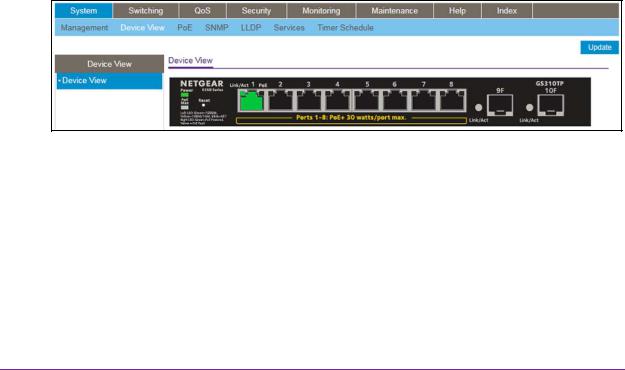
The Device View displays the ports on the switch. This graphic tool provides an alternate way to navigate to configuration and monitoring options. The graphic tool also provides information about device ports, configuration and status, tables, and feature components.
To use Device View:
1.Connect your computer to the same network as the switch.
You can use a WiFi or wired connection to connect your computer to the network, or connect directly to a switch that is off-network using an Ethernet cable.
2.Launch a web browser.
3.In the address field of your web browser, enter the IP address of the switch.
If you do not know the IP address of the switch, see Change the Default IP Address of the Switch on page 11.
The login window opens.
4.Enter the switch’s password in the Password field. The default password is password.
The System Information page displays.
5.Select System > Device View. The Device View page displays.
The following figure shows the Device View page for model GS310TP.
For model GS308T, depending upon the link status of the port, the left port LED and port color in the Device View are either green, yellow, or black:
•Green. The port is linking at a speed of 1 Gbps.
•Yellow. The port is linking at a speed of 10 Mbps or 100 Mbps.
•Black. No link is present.
Model GS308T provides a left port LED but no right port LED.
Get Started
24
S350 Series 8-Port Gigabit Ethernet Smart Managed Pro Switch Models GS308T and GS310TP
For model GS310TP, depending on the PoE status of the port, the right port LED and port color in the Device View are either green, yellow, or black:
•Green. The port is delivering PoE power.
•Yellow. A PoE fault occurred.
•Black. The port is not delivering PoE power.
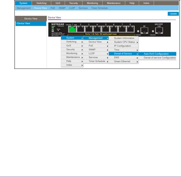
6.Click a port to open a menu that displays statistics and configuration options.
You can select a menu option to access the page that contains the configuration or monitoring options.
If you right-click the graphic, but do not right-click a specific port, the main menu displays. This menu contains the same options as the navigation tabs at the top of the page.
The following figure shows the details on the Device View page for model GS310TP.
Right-click the specific port that you want to view or configure to see a menu that displays statistics and configuration options. Select the menu option to access the page that contains the configuration or monitoring options.
The system LEDs are located on the left side of the front panel.
Power LED in the Device View
The Power LED is a bicolor LED that serves as an indicator of power and diagnostic status:
•Solid green. The switch is powered on and operating normally.
•Solid yellow. The switch is booting.
•Off. Power is not supplied to the switch.
PoE Max LED in the Device View (Model GS310TP)
The PoE Max LED indicates the following status:
•Off. Sufficient (more than 7W of) PoE power is available.
Get Started
25

S350 Series 8-Port Gigabit Ethernet Smart Managed Pro Switch Models GS308T and GS310TP
•Solid yellow. Less than 7W of PoE power is available.
•Blinking yellow. At least once during the previous two minutes, less than 7W of PoE power was available.
Interface Naming Conventions
The switch supports physical and logical interfaces. Interfaces are identified by their type and the interface number. The physical ports are Gigabit interfaces and are numbered on the front panel. You configure the logical interfaces by using the software.
The following table describes the naming convention for all interfaces available on the switch.
Table 3. Naming conventions for interfaces
Interface |
Description |
Example |
|
|
|
Physical |
The physical ports are Gigabit Ethernet |
g1, g2, g12 |
|
interfaces and are numbered |
|
|
sequentially starting from 1. |
|
|
|
|
Link aggregation group (LAG) |
LAG interfaces are logical interfaces |
l1, l2, l3 |
|
that are used only for bridging |
|
|
functions. |
|
|
|
|
CPU management interface |
This is the internal switch interface |
c1 |
|
responsible for the switch base MAC |
|
|
address. The interface is not |
|
|
configurable and is always listed in the |
|
|
MAC Address Table. |
|
|
|
|
Configure Interface Settings
For some features that allow you to configure interface settings, you can apply the same settings simultaneously to any of the following:
•A single port
•Multiple ports
•All ports
•A single LAG
•Multiple LAGs
•All LAGs
•Multiple ports and LAGs
•All ports and LAGs
Many of the pages that allow you to configure or view interface settings include links to display all ports, all LAGs, or all ports and LAGs on the page.
Get Started
26

S350 Series 8-Port Gigabit Ethernet Smart Managed Pro Switch Models GS308T and GS310TP
Use these links as follows:
•To display all ports, click the 1 link.
•To display all LAGs, click the LAG link.
•To display all ports and LAGs, click the All link.
The procedures in this section describe how to select the ports and LAGs to configure. The procedures assume that you are already logged in to the switch. If you do not know how to log in to the switch, see Navigation Tabs, Configuration Menus, and Page Menu on page 21.
To configure a single port by using the Go To Interface field:
1.Ensure that the page is displaying all ports, and not only the LAGs.
2.In the Go To Interface field, type the port number. For example, type g4.
For more information, see Interface Naming Conventions on page 26.
3.Click the Go button.
The check box associated with the interface is selected, the row for the selected interface is highlighted, and the interface number displays in the heading row.
4.Configure the desired settings.
5.Click the Apply button. Your settings are saved.
To configure a single LAG by using the Go To Interface field:
1.Click the LAG link or the All link to display the LAGs.
2.In the Go To Interface field, type the LAG number, for example l3. For information, see Interface Naming Conventions on page 26.
3.Click the Go button.
The check box associated with the interface is selected, the row for the selected interface is highlighted, and the interface number appears in the heading row.
4.Configure the desired settings.
5.Click the Apply button. Your settings are saved.
To configure a single port:
1.Ensure that the page is displaying all ports, and not only the LAGs.
2.Select the check box next to the port number.
The row for the selected interface is highlighted, and the interface number appears in the heading row.
3.Configure the desired settings.
Get Started
27

S350 Series 8-Port Gigabit Ethernet Smart Managed Pro Switch Models GS308T and GS310TP
4.Click the Apply button. Your settings are saved.
To configure a single LAG:
1.Click the LAG link or the All link to display the LAGs.
2.Select the check box next to the LAG number.
The row for the selected interface is highlighted, and the interface number appears in the heading row.
3.Configure the desired settings.
4.Click the Apply button. Your settings are saved.
To configure multiple ports:
1.Ensure that the page is displaying all ports, and not only the LAGs.
2.Select the check box next to each port to configure. The row for each selected interface is highlighted.
3.Configure the desired settings.
4.Click the Apply button. Your settings are saved.
To configure multiple LAGs:
1.Click the LAG link or the All link to display the LAGs.
2.Select the check box next to each LAG to configure.
The check box associated with each interface is selected, and the row for each selected interface is highlighted.
3.Configure the desired settings.
4.Click the Apply button. Your settings are saved.
To configure all ports:
1.Ensure that the page is displaying only ports, and not LAGs.
2.Select the check box in the heading row.
The check boxes for all ports are selected and the rows for all ports are highlighted.
3.Configure the desired settings.
4.Click the Apply button. Your settings are saved.
Get Started
28

S350 Series 8-Port Gigabit Ethernet Smart Managed Pro Switch Models GS308T and GS310TP
To configure all LAGs:
1.Click the LAG link to display only the LAG interfaces.
2.Select the check box in the heading row.
The check box associated with every LAG is selected, and the rows for all LAGs are highlighted.
3.Configure the desired settings.
4.Click the Apply button. Your settings are saved.
To configure multiple ports and LAGs:
1.Click the All link to display all ports and LAGs.
2.Select the check box associated with each port and LAG to configure. The rows for the selected ports and LAGs are highlighted.
3.Configure the desired settings.
4.Click the Apply button. Your settings are saved.
To configure all ports and LAGs:
1.Click the All link to display all ports and LAGs.
2.Select the check box in the heading row.
The check box associated with every port and LAG is selected, and the rows for all ports and LAGs are highlighted.
3.Configure the desired settings.
4.Click the Apply button. Your settings are saved.
Context-Sensitive Help and Access to the Support WebSite
When you log in to the switch, every page contains a link to the online help ( ) that contains information to assist in configuring and managing the switch. The online help pages are context sensitive. For example, if the IP Addressing page is open, the help topic for that page displays if you click the link to the online help.
From the local browser interface, you can access the NETGEAR support website at netgear.com/support.
Get Started
29

S350 Series 8-Port Gigabit Ethernet Smart Managed Pro Switch Models GS308T and GS310TP
To access the support website from the local browser interface:
1.Connect your computer to the same network as the switch.
You can use a WiFi or wired connection to connect your computer to the network, or connect directly to a switch that is off-network using an Ethernet cable.
2.Launch a web browser.
3.In the address field of your web browser, enter the IP address of the switch.
If you do not know the IP address of the switch, see Change the Default IP Address of the Switch on page 11.
The login window opens.
4.Enter the switch’s password in the Password field. The default password is password.
The System Information page displays.
5.Select Help > Support. The Support page displays.
6.To access the NETGEAR support site for the switch, click the Apply button.
Access the User Guide Online
The user manual (the guide you are now reading) is available at the NETGEAR download center at netgear.com/support/download/.
To access the user manual online from the local browser interface:
1.Connect your computer to the same network as the switch.
You can use a WiFi or wired connection to connect your computer to the network, or connect directly to a switch that is off-network using an Ethernet cable.
2.Launch a web browser.
3.In the address field of your web browser, enter the IP address of the switch.
If you do not know the IP address of the switch, see Change the Default IP Address of the Switch on page 11.
The login window opens.
4.Enter the switch’s password in the Password field. The default password is password.
The System Information page displays.
5.Select Help > Online Help > User Guide. The User Guide page displays.
Get Started
30
 Loading...