


Installation Guide for the 9 dBi Omni-directional Antenna ANT2409
NETGEAR, Inc.
4500 Great America Parkway
Santa Clara, CA 95054 USA
201-11248-01 April 2008

© 2008 by NETGEAR, Inc. All rights reserved.
Trademarks
NETGEAR, the NETGEAR logo, and Smart Wizard are trademarks or registered trademarks of NETGEAR, Inc. Microsoft, Windows, and Windows NT are registered trademarks of Microsoft Corporation. Other brand and product names are registered trademarks or trademarks of their respective holders.
Statement of Conditions
In the interest of improving internal design, operational function, and/or reliability, NETGEAR reserves the right to make changes to the products described in this document without notice. NETGEAR does not assume any liability that may occur due to the use or application of the product(s) or circuit layout(s) described herein.
Federal Communications Commission (FCC) Compliance Notice: Radio Frequency Notice
In the U.S., the ANT2409 antenna should only be used with devices that have been FCC approved for use with it. Please check the NETGEAR web site at http://www.NETGEAR.com/go/antannas_fcc for an updated list of FCC
approved devices.
European Emission Statement
For EU, use of any antenna requires careful planning and extra consideration to comply with EU emissions, health standards and regulations. It is recommended that a qualified professional installer service is consulted for site survey and proper installation. Antenna installation must comply with the maximum level authorized by each country. See http:/ /www.NETGEAR.com/go/antannas_eu for product combinations that comply with EU regulations.
ii
Publication Version 1.0, April 2008

Contents
Chapter 1
Getting Started
Package Contents .......................................................................................................... |
1-1 |
Pole Mounting Configuration .......................................................................................... |
1-3 |
Flat Surface Mounting Configuration .............................................................................. |
1-4 |
Placement and Other Important Considerations ............................................................ |
1-4 |
Chapter 2 |
|
Installing the Wireless Antenna |
|
First, Assemble and Mount the Antenna ........................................................................ |
2-1 |
Now, Connect the Antenna ............................................................................................ |
2-4 |
Connecting the Antenna for and Outdoor Installation .............................................. |
2-4 |
Connecting the Antenna for an Indoor Installation ................................................... |
2-5 |
Chapter 3 |
|
Specifications |
|
Wireless Antenna and Mounting Assembly .................................................................... |
3-1 |
2 Meter Antenna Cable ................................................................................................... |
3-2 |
N/SMA Adaptor Accessory ............................................................................................. |
3-3 |
Lightning Arrestor Specifications .................................................................................... |
3-4 |
Radiation Patterns .......................................................................................................... |
3-5 |
v
Publication Version 1.0, April 2008

vi
Publication Version 1.0, April 2008
Chapter 1
Getting Started
Thank you for purchasing the NETGEAR 9 dBi Omni-directional Antenna. This Installation Guide provides installation instructions and guidelines for using the wireless antenna.
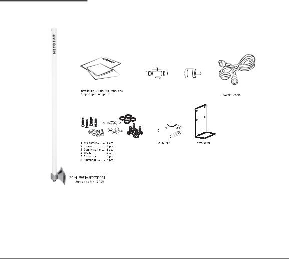
Package Contents
|
|
|
Reverse N/SMA |
Lightning |
|||
arrestor |
adapter |
||
Figure 1-1
The package should contain the following items:
•NETGEAR 9 dBi Omni-directional Antenna
•2-meter low loss antenna cable to connect the antenna to a lightning arrestor
1-1
v1.0, April 2008

Installation Guide for the 9 dBi Omni-directional Antenna ANT2409
•Lightning Arrestor
Note: A ground cable is not included but required for outdoor installation. The grounding cable must be equivalent or better than: AWG 10, UL 1015, Stranded, 600 V, 105 oC, green or green/yellow insulation, 2 clip of 5.5 mm inner diameter cramped at both ends, cable no longer than 5 meters
•Reverse N/SMA Adapter
•Antenna mounting assembly (tube, grommet, 2 brackets, screws, washers)
•L shape bracket for top & ceiling mounting
•Screws, bolts, washers, U-bolts and plastic anchors
•This Installation Guide, and a Warranty and Support Information card
If any of the parts are incorrect, missing, or damaged, contact your NETGEAR dealer. Keep the carton, including the original packing materials, in case you need to return the product for repair.
To obtain optimal results in extending wireless range with antenna installations, consult a qualified professional installer for site survey and installation assistance.
Antenna cable for connecting the wireless device is sold separately. Please use a NETGEAR model ACC-10314-01, 02, 03, 04, or 05 cable.
In the U.S., the ANT2409 antenna should only be used with devices that have been FCC approved for use with it. Please check the NETGEAR website at http://www.NETGEAR.com/go/antennas_fcc for an updated list of FCC approved devices.
For Europe, use of any antenna requires careful planning and extra consideration to comply with EU emissions and health standards and regulations. Antenna installation must comply with the maximum level authorized by each country. Please check the NETGEAR website at http://www.NETGEAR.com/go/antennas_eu for a list of restrictions and approved devices.
1-2
v1.0, April 2008
Installation Guide for the 9 dBi Omni-directional Antenna ANT2409
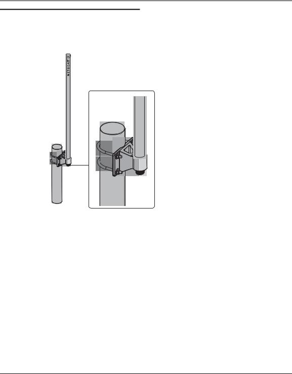
Pole Mounting Configuration
The following illustration shows the pole mount configuration option.
Figure 1-2
1-3
v1.0, April 2008

Installation Guide for the 9 dBi Omni-directional Antenna ANT2409
Flat Surface Mounting Configuration
This illustration shows a flat surface mount configuration.
Wall Mount
R
Figure 1-3
For wall mount installation, the L-bracket is not used.
Placement and Other Important Considerations
Before installing your wireless antenna, observe the placement considerations. Antenna placement dramatically affects potential coverage. Follow these guidelines to maximize coverage:
•Place the antenna in a vertical position. Either right side up or up-side-down is OK.
•Place the antenna in the middle of the coverage zone and at 1.5m or higher above the floor.
1-4
v1.0, April 2008
 Loading...