


 Loading...
A New Direction In Cutting-Edge Technology
DIRECT ION™ SP B-SERIES
S E R V I C E A N D R E F E R E N C E
M A N U A L
Proprietary Notice and Liability Disclaimer
The information disclosed in this document, including all designs and related materials, is the valuable property of NEC Computer Systems Division, Packard Bell NEC, Inc. (hereinafter “NEC CSD”) and/or its licensors. NEC CSD and/or its licensors, as appropriate, reserve all patent, copyright and other proprietary rights to this document, including all design, manufacturing, reproduction, use, and sales rights thereto, except to the extent said rights are expressly granted to others.
The NEC CSD product(s) discussed in this document are warranted in accordance with the terms of the Warranty Statement accompanying each product. However, actual performance of each such product is dependent upon factors such as system configuration, customer data, and operator control. Since implementation by customers of each product may vary, the suitability of specific product configurations and applications must be determined by the customer and is not warranted by NEC CSD.
To allow for design and specification improvements, the information in this document is subject to change at any time, without notice. Reproduction of this document or portions thereof without prior written approval of NEC CSD is prohibited.
FaxFlash is a service mark of NEC Computer Systems Division, Packard Bell NEC, Inc.
Direction and VistaScan are trademarks of Packard Bell NEC, Inc.
NEC and MultiSync are registered trademarks of NEC Corporation, used under license.
All other product, brand, or trade names used in this publication are the trademarks or registered trademarks of their respective trademark owners.
First Printing — April 1999
Copyright 1999
NEC Computer Systems Division
Packard Bell NEC, Inc.
1 Packard Bell Way
Sacramento, CA 95828-0903
All Rights Reserved

Contents
|
Preface ............................................................................................................................. |
ix |
|
Abbreviations ................................................................................................................... |
xi |
1 |
Technical Information |
|
|
System Overview .......................................................................................................... |
1-2 |
|
System Board ................................................................................................................ |
1-5 |
|
Processor.................................................................................................................. |
1-5 |
|
System Cache/Memory............................................................................................. |
1-5 |
|
Chipset ..................................................................................................................... |
1-6 |
|
PCI Local Bus .......................................................................................................... |
1-6 |
|
Expansion Bus .................................................................................................. |
1-6 |
|
BIOS ........................................................................................................................ |
1-6 |
|
Plug and Play Support....................................................................................... |
1-7 |
|
CMOS Memory/Real-Time Clock Battery ................................................................ |
1-7 |
|
DMA/IRQ Settings................................................................................................... |
1-7 |
|
IDE Ports ................................................................................................................. |
1-9 |
|
I/O Ports................................................................................................................... |
1-9 |
|
Sound System........................................................................................................... |
1-9 |
|
Modem Board (optional) .............................................................................................. |
1-10 |
|
Diskette Drive .............................................................................................................. |
1-10 |
|
Hard Drive ................................................................................................................... |
1-10 |
|
CD-ROM/DVD Drive .................................................................................................. |
1-10 |
|
Zip Drive...................................................................................................................... |
1-10 |
|
Power Supply ............................................................................................................... |
1-10 |
|
Power Management ...................................................................................................... |
1-11 |
2 |
Utilities |
|
|
BIOS Setup Utility ........................................................................................................ |
2-2 |
|
When to Use Setup ................................................................................................... |
2-2 |
|
How to Start Setup ................................................................................................... |
2-3 |
|
How to Use Setup..................................................................................................... |
2-3 |
|
Menu Bar ................................................................................................................. |
2-4 |
|
Legend Bar............................................................................................................... |
2-5 |
|
Selecting a Menu Item .............................................................................................. |
2-5 |
|
Displaying a Submenu.............................................................................................. |
2-5 |
|
Getting Help............................................................................................................. |
2-5 |
|
Main Menu............................................................................................................... |
2-6 |
|
Advanced Menu ....................................................................................................... |
2-7 |
|
Peripheral Configuration Submenu.................................................................... |
2-7 |
|
IDE Configuration Submenu ............................................................................. |
2-8 |
|
Floppy Options Submenu................................................................................. |
2-10 |
|
DMI Event Logging Submenu.......................................................................... |
2-11 |
|
Video Configuration Submenu ......................................................................... |
2-11 |
|
Resource Configuration Submenu .................................................................... |
2-12 |
|
Security Menu ......................................................................................................... |
2-12 |
|
Power Menu ............................................................................................................ |
2-13 |
Contents iii

|
Boot Menu .............................................................................................................. |
2-13 |
|
Hard Drive Submenu ....................................................................................... |
2-14 |
|
Removable Devices Submenu .......................................................................... |
2-14 |
|
Exit Menu ............................................................................................................... |
2-15 |
|
Intel Processor Serial Number Control Utility............................................................... |
2-15 |
|
System Requirements .............................................................................................. |
2-16 |
|
Processor Serial Number ......................................................................................... |
2-16 |
|
FAQs ...................................................................................................................... |
2-16 |
|
Errata ...................................................................................................................... |
2-18 |
|
Technical Support ................................................................................................... |
2-18 |
3 |
Option Installation |
|
|
General Rules ................................................................................................................ |
3-2 |
|
Precautions.................................................................................................................... |
3-2 |
|
Access Cover Removal.................................................................................................. |
3-3 |
|
Access Cover Replacement............................................................................................ |
3-4 |
|
Expansion Boards.......................................................................................................... |
3-5 |
|
Expansion Slot Locations ......................................................................................... |
3-6 |
|
Expansion Board Installation .................................................................................... |
3-6 |
|
Expansion Board Removal ....................................................................................... |
3-8 |
|
Memory Upgrade .......................................................................................................... |
3-8 |
|
DIMM Removal ...................................................................................................... |
3-10 |
|
DIMM Installation................................................................................................... |
3-11 |
|
Data Storage Devices.................................................................................................... |
3-11 |
|
Device Slots ............................................................................................................ |
3-12 |
|
Device Preparation .................................................................................................. |
3-12 |
|
Device Cables ......................................................................................................... |
3-13 |
|
Diskette Drive Signal Cable ............................................................................. |
3-14 |
|
IDE Signal Cables............................................................................................ |
3-14 |
|
System Power Cables....................................................................................... |
3-15 |
|
Device Cabling........................................................................................................ |
3-16 |
|
Cabling an IDE Device .................................................................................... |
3-16 |
|
Cabling an Accessible 5 1/4-Inch Device ......................................................... |
3-16 |
|
Storage Device Installation ...................................................................................... |
3-17 |
|
Removing the Front Panel ................................................................................ |
3-17 |
|
Removing the CD-ROM/DVD Drive ............................................................... |
3-18 |
|
Installing a 3 1/2-Inch Device........................................................................... |
3-19 |
|
Installing a 5 1/4-Inch Device........................................................................... |
3-23 |
|
Replacing the Front Panel ................................................................................ |
3-24 |
|
External Options........................................................................................................... |
3-25 |
|
Parallel Printer......................................................................................................... |
3-25 |
|
RS-232C Device Connection ................................................................................... |
3-26 |
4 |
Maintenance and Troubleshooting |
|
|
Maintenance.................................................................................................................. |
4-2 |
|
System Cleaning....................................................................................................... |
4-3 |
|
Keyboard Cleaning................................................................................................... |
4-3 |
|
Mouse Cleaning ....................................................................................................... |
4-3 |
|
Troubleshooting ............................................................................................................ |
4-4 |
|
Diagnosing and Solving Problems ............................................................................ |
4-4 |
|
Beep Codes .............................................................................................................. |
4-9 |
|
CMOS Battery Replacement.................................................................................... |
4-10 |
iv Contents

5 Disassembly and Reassembly |
|
Disassembly .................................................................................................................. |
5-3 |
System Access Cover ............................................................................................... |
5-3 |
Expansion Board Removal ....................................................................................... |
5-3 |
Front Panel Removal ................................................................................................ |
5-4 |
Side Panel Removal.................................................................................................. |
5-5 |
Device Cage Removal .............................................................................................. |
5-5 |
Diskette Drive Removal............................................................................................ |
5-6 |
5 1/4-Inch Device Removal ...................................................................................... |
5-6 |
Optional 3 1/2-Inch Hard Drive Removal.................................................................. |
5-7 |
Standard 3 1/2-Inch Hard Drive Removal ................................................................. |
5-8 |
Fan Assembly Removal ............................................................................................ |
5-9 |
DIMM Module Removal .......................................................................................... |
5-9 |
Power Supply Removal ............................................................................................ |
5-9 |
System Board Removal ........................................................................................... |
5-10 |
Illustrated Parts Breakdown.......................................................................................... |
5-12 |
A System Specifications |
|
Processor....................................................................................................................... |
A-2 |
Random Access Memory............................................................................................... |
A-2 |
Read-Only Memory....................................................................................................... |
A-3 |
Video Memory .............................................................................................................. |
A-3 |
Calendar Clock.............................................................................................................. |
A-3 |
Input/Output Facilities ................................................................................................... |
A-3 |
Expansion Slots ............................................................................................................. |
A-4 |
Keyboard and Mouse..................................................................................................... |
A-4 |
Storage Devices............................................................................................................. |
A-4 |
Device Slots .................................................................................................................. |
A-4 |
Graphics........................................................................................................................ |
A-5 |
Sound System................................................................................................................ |
A-6 |
Dimensions ................................................................................................................... |
A-6 |
Weight .......................................................................................................................... |
A-6 |
Power ............................................................................................................................ |
A-6 |
Recommended Operating Environment.......................................................................... |
A-7 |
B Connector Pin Assignments
Serial Interface Connectors............................................................................................ |
B-5 |
Parallel Interface Connector........................................................................................... |
B-5 |
Power Supply (Primary) ................................................................................................ |
B-6 |
Keyboard and Mouse Connectors .................................................................................. |
B-7 |
Front Panel.................................................................................................................... |
B-7 |
Diskette Drive Interface Connector................................................................................ |
B-8 |
IDE Interface Connector................................................................................................ |
B-9 |
DIMM Sockets ............................................................................................................ |
B-10 |
AGP Connector ........................................................................................................... |
B-11 |
ISA Expansion Bus Connectors ................................................................................... |
B-13 |
PCI Expansion Bus Connectors ................................................................................... |
B-15 |
Universal Serial Bus (USB) Connectors....................................................................... |
B-16 |
Contents v

C System Resources
IRQ Settings.................................................................................................................. |
C-2 |
System Resource Information ........................................................................................ |
C-2 |
Jumper Settings ............................................................................................................. |
C-3 |
Clearing Your Password ........................................................................................... |
C-4 |
Recovering the BIOS................................................................................................ |
C-5 |
vi Contents

List of Figures |
|
Front Features – Desktop Models .......................................................................................... |
1-2 |
Rear Features – Desktop Models ........................................................................................... |
1-3 |
Audio Connectors – Desktop Models .................................................................................... |
1-3 |
Front Features – Minitower Models....................................................................................... |
1-4 |
Rear Features – Minitower Models........................................................................................ |
1-4 |
Audio Connectors – Minitower Models ................................................................................. |
1-5 |
Main Setup Menu.................................................................................................................. |
2-3 |
Releasing the Cover .............................................................................................................. |
3-4 |
Aligning the Tabs ................................................................................................................. |
3-5 |
Locating Expansion Slots ...................................................................................................... |
3-6 |
Removing the Slot Cover ...................................................................................................... |
3-7 |
Installing a Board.................................................................................................................. |
3-8 |
Removing a DIMM.............................................................................................................. |
3-10 |
Installing a DIMM ............................................................................................................... |
3-11 |
Locating Device Slots .......................................................................................................... |
3-12 |
System Board Cable Connectors .......................................................................................... |
3-13 |
Diskette Drive Signal Cable ................................................................................................. |
3-14 |
IDE Signal Cable ................................................................................................................. |
3-15 |
Power Cable Connectors ...................................................................................................... |
3-15 |
Connecting IDE Device Cables ............................................................................................ |
3-16 |
Connecting an Accessible 5 1/4-Inch Device........................................................................ |
3-17 |
Releasing the Front Panel..................................................................................................... |
3-18 |
Locating the Device Cage Screw.......................................................................................... |
3-18 |
Locating Device Slots .......................................................................................................... |
3-19 |
Removing the Bracket Screws.............................................................................................. |
3-20 |
Aligning the Holes and Tabs ................................................................................................ |
3-20 |
Securing the Drive ............................................................................................................... |
3-21 |
Inserting the Device ............................................................................................................. |
3-21 |
Removing the Blank Panel ................................................................................................... |
3-22 |
Installing the Device ............................................................................................................ |
3-24 |
Locating the Parallel Port ..................................................................................................... |
3-25 |
Locating the Serial Ports ...................................................................................................... |
3-26 |
Locating the Mouse Ball Cover ............................................................................................. |
4-4 |
Locating the Battery............................................................................................................. |
4-10 |
Removing a Board ................................................................................................................ |
5-4 |
Releasing the Front Panel...................................................................................................... |
5-4 |
Locating the Device Cage Screw........................................................................................... |
5-5 |
Locating the Two Diskette Drive Clips.................................................................................. |
5-6 |
Removing the 5 1/4-Inch Device Screws ............................................................................... |
5-7 |
Removing the Bracket Screws............................................................................................... |
5-7 |
Removing the Securing Screw............................................................................................... |
5-8 |
Removing the Drive.............................................................................................................. |
5-8 |
Removing a DIMM............................................................................................................... |
5-9 |
Removing the Power Supply Screws .................................................................................... |
5-10 |
Removing the System Board Screw...................................................................................... |
5-11 |
Direction SP B-Series Desktop Illustrated Parts Breakdown ................................................. |
5-14 |
Direction SP B-Series Minitower Illustrated Parts Breakdown.............................................. |
5-17 |
System Board Expansion Slot, Memory, and I/O Connectors ................................................ |
B-3 |
System Board Connectors and Jumper................................................................................... |
B-3 |
Locating the Jumper.............................................................................................................. |
C-3 |
Contents vii

List of Tables
System Memory Map............................................................................................................ |
1-7 |
Interrupt Level Assignments ................................................................................................. |
1-8 |
DMA Assignments................................................................................................................ |
1-8 |
Setup Key Functions ............................................................................................................. |
2-5 |
Sample Memory Configurations............................................................................................ |
3-9 |
NEC CSD Service and Information Telephone Numbers ....................................................... |
4-2 |
Problems and Solutions......................................................................................................... |
4-5 |
Beep Code Descriptions ........................................................................................................ |
4-9 |
Disassembly Sequence .......................................................................................................... |
5-2 |
Direction SP B-Series Desktop Field-Replaceable Parts List ................................................ |
5-12 |
Direction SP B-Series Minitower Field-Replaceable Parts List ............................................. |
5-15 |
System Board Connectors ..................................................................................................... |
B-2 |
System Board Internal Connectors ........................................................................................ |
B-4 |
System Board Connector Numbers and Types ....................................................................... |
B-4 |
RS-232C Serial Port Connector Pin Assignments .................................................................. |
B-5 |
Parallel Port Connector Pin Assignments............................................................................... |
B-5 |
Primary Power Supply Connector Pin Assignments............................................................... |
B-6 |
Keyboard and Mouse Connector Pin Assignments................................................................. |
B-7 |
Front Panel Connector Pin Assignments................................................................................ |
B-7 |
Diskette Drive Connector Pin Assignments ........................................................................... |
B-8 |
IDE/PCI Connector Pin Assignments .................................................................................... |
B-9 |
DIMM Socket Pin Assignments .......................................................................................... |
B-10 |
AGP Connector Pin Assignments ........................................................................................ |
B-11 |
ISA Expansion Slot Pin Assignments .................................................................................. |
B-13 |
PCI Expansion Slot Pin Assignments .................................................................................. |
B-15 |
USB Connectors ................................................................................................................. |
B-16 |
System Board Jumper Settings .............................................................................................. |
C-3 |
viii Contents

Preface
This service and reference manual contains technical information necessary for servicing and repairing Direction™ SP B-Series systems. The manual includes system setup information, procedures for installing options, and troubleshooting. The manual is written for NEC CSD-trained customer engineers, system analysts, service center personnel, and dealers.
The manual is organized as follows:
Section 1 — Technical Information , provides an overview of the computer features, hardware design, interface ports, and internal devices.
Section 2 — Utilities , includes procedures for configuring the system through the Setup utility program and information on the Intel® Processor Serial Number Control utility.
Section 3 — Option Installation, provides installation procedures for adding optional expansion boards, diskette and hard drive storage devices, and system memory.
Section 4 — Maintenance and Troubleshooting , includes recommended maintenance information, lists possible computer problems and their solutions, and has battery replacement procedures.
Section 5 — Disassembly and Reassembly , includes computer disassembly and reassembly procedures.
Appendix A — System Specifications , provides a list of the system specifications including dimensions, weight, environment, safety compliance, power consumption, and memory.
Appendix B — Connector Pin Assignments , provides a list of the internal and external system board connector pin assignments.
Appendix C — System Resources , includes information on IRQ settings and system board jumpers.
Preface ix

Abbreviations
A |
ampere |
AC |
alternating current |
AT |
advanced technology |
|
(IBM PC) |
BBS |
Bulletin Board Service |
BCD |
binary-coded decimal |
BCU |
BIOS Customized Utility |
BIOS |
basic input/output system |
bit |
binary digit |
BUU |
BIOS Upgrade Utility |
bpi |
bits per inch |
bps |
bits per second |
C |
capacitance |
C |
centigrade |
Cache |
high-speed buffer storage |
CAM |
constantly addressable |
|
memory |
CAS |
column address strobe |
CD/ROM |
compact disk-ROM |
CG |
character generator |
CGA |
Color Graphics Adapter |
CGB |
Color Graphics Board |
CH |
channel |
clk |
clock |
cm |
centimeter |
CMOS |
complementary metal oxide |
|
semiconductor |
COM |
communication |
CONT |
contrast |
CPGA |
ceramic pin grid array |
CPU |
central processing unit |
DAC |
digital-to-analog converter |
DACK |
DMA acknowledge |
DC |
direct current |
DIP |
dual in-line package |
DLAB |
Divisor Latch Address bit |
DMA |
direct memory access |
DMAC |
DMA controller |
DOS |
disk operating system |
DRAM |
dynamic RAM |
ECC |
error checking and correction |
EDO |
extended data output |
EGA |
Enhanced Graphics Adapter |
EPROM |
erasable and programmable |
|
ROM |
EVGA |
Enhanced Video Graphics |
|
Array |
F |
Fahrenheit |
FAX |
facsimile transmission |
FCC |
Federal Communications |
|
Commission |
FG |
frame ground |
FM |
frequency modulation |
FP |
fast page |
FRU |
field-replaceable unit |
FSB |
front side bus |
GB |
gigabyte |
GND |
ground |
HEX |
hexadecimal |
HGA |
Hercules Graphics Adapter |
Hz |
hertz |
IC |
integrated circuit |
ID |
identification |
IDE |
intelligent device electronics |
IDTR |
interrupt descriptor table |
|
register |
in. |
inch |
INTA |
interrupt acknowledge |
IPB |
illustrated parts breakdown |
IR |
infrared |
IRR |
Interrupt Request register |
ISA |
Industry Standard |
|
Architecture |
ISR |
In Service register |
I/O |
input/output |
xi
IPC |
integrated peripheral |
|
controller |
ips |
inches per second |
IRQ |
interrupt request |
K |
kilo (1024) |
k |
kilo (1000) |
KB |
kilobyte |
kg |
kilogram |
kHz |
kilohertz |
lb |
pound |
LED |
light-emitting diode |
LSB |
least-significant bit |
LSI |
large-scale integration |
M |
mega |
mA |
milliamps |
max |
maximum |
MB |
megabyte |
MDA |
Monochrome Display Adapter |
MFM |
modified frequency |
|
modulation |
MHz |
megahertz |
mm |
millimeter |
ms |
millisecond |
MSB |
most-significant bit |
NASC |
National Authorized Service |
|
Center |
NC |
not connected |
NMI |
Non-maskable Interrupt |
ns |
nanosecond |
NSRC |
National Service Response |
|
Center |
PAL |
programmable array logic |
PC |
personal computer |
PCB |
printed circuit board |
PCI |
Peripheral Component |
|
Interconnect |
PDA |
personal digital assistant |
PFP |
plastic flat package |
PIO |
parallel input/output |
pixel |
picture element |
PLCC |
plastic leaded chip carrier |
PLL |
phase lock loop |
p-p |
peak-to-peak |
PPI |
programmable peripheral |
|
interface |
PROM |
programmable ROM |
QFP |
quad flat pack |
RAM |
random-access memory |
RAMDAC |
RAM digital-to-analog |
|
converter |
RAS |
row address strobe |
RGB |
red green blue |
RGBI |
red green blue intensity |
ROM |
read-only memory |
rpm |
revolutions per minute |
R |
read |
RTC |
real-time clock |
R/W |
read/write |
S |
slave |
SCSI |
Small Computer System |
|
Interface |
SG |
signal ground |
SIMM |
single inline memory module |
SPM |
standard page mode |
SRS |
Sound Retrieval System |
SVGA |
Super Video Graphics Array |
SW |
switch |
TAC |
Technical Assistance Center |
TSC |
Technical Support Center |
TTL |
transistor/transistor logic |
tpi |
tracks per inch |
USB |
universal serial bus |
V |
volt |
Vac |
volts, alternating current |
Vdc |
volts, direct current |
VESA |
video electronics standards |
|
association |
VFC |
VESA-compliant feature |
|
connector |
VGA |
Video Graphics Array |
VRAM |
video RAM |
W |
watt |
xii
1
Technical Information
TOverview
TSystem Board
TModem Board (optional)
TDiskette Drive
THard Drive
TCD-ROM/DVD Drive
TZip Drive
TPower Supply
TPower Management

The section provides an overview of the NEC Direction™ SP B-Series computers. Information includes:
Tan overview of system features
Tdescription of system components.
System Overview
NEC Direction SP B-Series systems support the Intel® Pentium® II processor with MMX™ technology. The following figures show system features on the front and rear of the desktop and minitower systems. The subsections that follow provide more detailed information on system features.
Front Features – Desktop Models
A – Power Lamp |
B – Power Button |
C – Disk Lamp |
D – Reset Button |
E – Diskette Drive |
F – CD-ROM/DVD Drive |
1-2 Technical Information
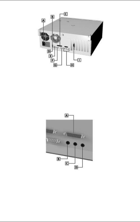
Rear Features – Desktop Models
A – Power Socket |
B – Mouse Port |
C – Parallel Port |
D – Keyboard Port |
E – USB Ports |
F – Serial Port 1 |
G – Serial Port 2 |
H – Audio Connectors |
I – Video Connector |
|
Audio Connectors – Desktop Models
A – MIDI/Game Port |
B – Line Out Jack |
C – Line In Jack |
D – Microphone Jack |
Technical Information 1-3
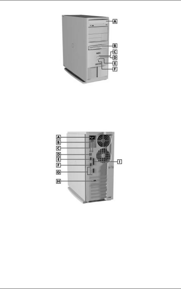
Front Features – Minitower Models
A – CD-ROM/DVD Drive |
B – Diskette Drive |
C – Power Lamp |
D – Power Button |
E – Disk Lamp |
F – Reset Button |
Rear Features – Minitower Models
A – Power Socket |
B – Mouse Port |
C – Keyboard Port |
D – USB Ports |
E – Serial Port 1 |
F – Serial Port 2 |
G – Audio Connectors |
H – Video Connector |
I – Parallel Port |
|
1-4 Technical Information
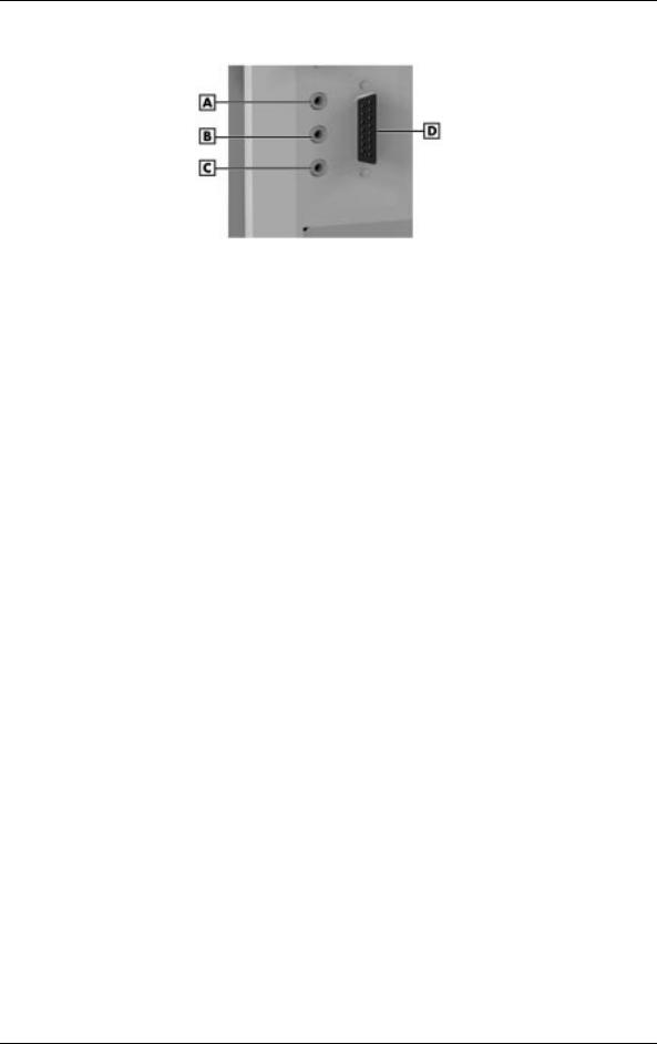
Audio Connectors – Minitower Models
A – Line Out Jack |
B – Line In Jack |
C – Microphone Jack |
D –MIDI/Game Port |
System Board
The system board contains most of the components that provide system functions. The following subsections provide a description of these components.
Processor
The system board uses a 350-MHz, 400-MHz, or 450-MHz Intel Pentium II processor or a 500-MHz Intel Pentium III processor. All use MMX technology. The MMX processor improves audio, video, and 3D graphics performance.
Each processor is packaged in a Single Edge Contact (SEC) cartridge that plugs into the system board’s slot 1.
System Cache/Memory
To use the processor’s power, the system features an optimized 64-bit memory interface and provides support for a second level cache to complement the processor’s internal cache.
High-performance features include:
Tpipeline 32-bit addressing
T64-bit data
T512-KB of pipeline burst secondary cache; direct mapped write-back and write-through organization.
The system comes with 32 to 384 MB of main system memory. Three sockets on the system board support up to 384 MB of high-speed memory using industry-standard gold-plated dual in-line memory modules (DIMMs).
The system supports PC100-MHz Synchronous DRAM (SDRAM) only.
Technical Information 1-5

The system supports the following DIMM configurations:
T4-Mbit by 64 (32-MB DIMM)
T8-Mbit by 64 (64-MB DIMM)
T16-Mbit by 64 (128-MB DIMM).
Chipset
The Intel 440BX chipset provides DMA, memory, and bus control. The chipset includes the following chips:
TIntel 82443BX PCI/AGP (PAC) ¾ provides bus-control signals, address paths, and data paths for transfers between the processor’s host bus, PCI bus, Accelerated Graphics Port (AGP), and main memory.
TIntel 82371EB PCI ISA IDE Xcelerator (PIIX4E) ¾ implements the PCI-to-ISA bridge, PCI IDE functionality, Universal Serial Bus (USB) host/hub functions, and enhanced power management.
PCI Local Bus
The 32-bit industry-standard PCI bus is a highly-integrated input/output (I/O) interface that offers the highest performance local bus available for the Pentium II processor. The PCI bus supports burst modes that send large chunks of data across the bus, allowing fast displays of high-resolution images.
The high-bandwidth PCI local bus eliminates data bottlenecks found in traditional systems, maintains maximum performance at high clock speeds, and provides a clear upgrade path to future technologies.
The PCI bus contains two embedded PCI devices: the PCI local bus IDE interface and the PCI video/graphics controller. The PCI bus also contains a connector for attaching the bus expansion board.
Expansion Bus
The expansion bus contains one ISA slot, three PCI slots, one PCI/ISA slot, and one AGP video slot. The PCI ISA IDE Xcelerator chip (PIIX4E) provides the logic that enables the ISA bus functions. With 24-bit memory addressing, a 16-bit data path, and an 8-MHz clock, the ISA bus is designed to support all peripherals compatible with the IBM® AT™ standard. For PCI functions, the Xcelerator chip provides 32-bit memory addressing, 32-bit data path, and a 33-MHz clock speed.
BIOS
The BIOS (Basic Input Output System) is stored in the Flash EPROM. The Flash EPROM is reprogrammable and allows fast, economical BIOS upgrades.
The system memory map is shown in the following table.
1-6 Technical Information

System Memory Map
Memory Address |
Size |
Function |
100000-18000000 |
383 MB |
Extended memory |
E8000-FFFFF |
96 KB |
System BIOS |
E0000-E7FFF |
32 KB |
System BIOS (available as |
|
|
UMB) |
C8000-DFFFF |
96 KB |
Available high DOS memory |
|
|
(open to ISA and PCI bus) |
A0000-C7FFF |
160 KB |
Video memory and BIOS |
00000-9FFFF |
640 KB |
Conventional memory |
|
|
|
Plug and Play Support
The system comes with Plug and Play BIOS technology. Plug and Play eliminates complicated setup procedures for installing Plug and Play expansion boards.
To add a Plug and Play expansion board, simply power off the system, install the board, and power on the system. There are no jumpers to set and no system resource conflicts to resolve. Plug and Play automatically configures the board for the system. The system also supports non-Plug and Play boards.
Plug and Play is controlled by the Plug and Play BIOS and the system’s operating system. The Plug and Play BIOS is stored in the Flash EPROM on the system board.
The Plug and Play BIOS adds several steps to the POST process. During POST, the Plug and Play evaluates the configuration of installed boards and assigns available system resources to the devices. On completion of Plug and Play POST, the operating system checks to see if there are any additional resources required, then assigns available resources to the devices.
CMOS Memory/Real-Time Clock Battery
The 82371EB PCI ISA IDE Xcelerator (PIIX4E) on the system board stores system information in non-volatile CMOS memory. The chip also contains the system’s real-time clock. Both are maintained by a 3-volt coin cell lithium battery on the system board. The battery is replaceable.
DMA/IRQ Settings
The system automatically configures, with minimal user intervention, interrupt requests (IRQ), direct memory access (DMA) channels, and other parameters when adding PCI boards.
The following tables list system IRQ and DMA default settings.
Technical Information 1-7

|
Interrupt Level Assignments |
|
|
IRQ |
System Resource |
|
|
NMI |
I/O channel check |
00 |
Reserved, interval timer |
01 |
Reserved, keyboard controller |
02 |
Reserved, cascade interrupt from slave PIC |
03 |
COM2* |
04 |
COM1* |
05 |
LPT2 (Plug and Play option)/audio/user available |
06 |
Diskette drive |
07 |
LPT1* |
08 |
Real-time clock |
09 |
Reserved |
10 |
USB/user available |
11 |
Windows Sound System*/user available |
12 |
PS/2 mouse port (if present, else user available) |
13 |
Reserved, numeric processor |
14 |
Primary IDE (if present, else user available) |
15 |
Secondary IDE (if present, else user available) |
|
|
* Default; setting can be changed. |
|
|
DMA Assignments |
|
|
DMA |
Resource |
|
|
00 |
Audio |
01 |
Audio/parallel port |
02 |
Diskette drive |
03 |
ECP parallel port/audio |
04 |
Reserved, cascade channel |
05 |
Available |
06 |
Available |
07 |
Available |
|
|
1-8 Technical Information

IDE Ports
The system board provides two fast IDE ports: primary channel and secondary channel.
Each port supports two devices for a total of four IDE devices. The system board allows the connection of an IDE CD-ROM drive for system configuration flexibility without the addition of a controller.
The IDE ports feature an enhanced IDE interface which supports up to 16.7 MB per second 32-bit wide data transfers on the high-performance PCI local bus. The standard hard drive and Zip® drive (in some systems) are connected to the primary channel. The CD-ROM drive is attached to the secondary channel.
I/O Ports
The system board features an enhanced parallel port, two buffered high-speed serial ports, and two Universal Serial Bus (USB) ports.
The enhanced parallel port supports Enhanced Capabilities Port (ECP) and Enhanced Parallel Port (EPP) modes for devices that require ECP or EPP protocols. These protocols allow high-speed bi-directional transfer over a parallel port and increase parallel port functionality by supporting more devices.
The two buffered high-speed serial ports use a fast 16C550 UART which supports transfer rates up to 115.2 kilobits (Kb) per second. These ports allow the installation of high-speed serial devices for faster data transfer rates.
The two USB ports allow additional new plug and play serial devices without removing the system cover. Simply plug the USB device into the port. The speed varies between 12 megabits per second (Mbps) for printers and 1.5 Mbps for mice and keyboards. Up to 127 USB devices can be connected to the computer.
The combination of the enhanced parallel port, buffered serial ports, and USB ports ensure optimum performance for future peripheral devices and operating systems.
Sound System
The system board features the Yamaha® DS1-L PCI accelerator and Analog Devices AD1819A SoundPort codec. The chips provide the following:
T32-voice XG wavetable
T3D stereo enhancement
TSupport for DirectX
TFull-duplex audio
TPC/PCI support for legacy DMAC emulation.
Technical Information 1-9
The optional AWE64D PCI sound board replaces the integrated audio system. It provides FM synthesis and 64 simultaneous voices.
Modem Board (optional)
Optional modem boards include: U.S. Robotics® 56-Kbps V.90 x2-capable Winmodem, U.S. Robotics 56-Kbps V.90 x2-capable Sportster, and the Diamond Supra 56i K56Flex V.90 PCI modem. Each modem board contains fax and modem capabilities. The Winmodem provides only fax and modem capabilities. The other two boards provide modem, fax, full-duplex speakerphone, and voicemail capabilities. Each board provides receive transfer rates of 56-Kbps (kilobytes per second) for data and 14.4-Kbps for fax.
Diskette Drive
The system comes standard with a 1.44-MB high-density diskette drive preinstalled in the 3 1/2-inch accessible device slot (drive A). The drive is connected to the system board via a two-connector cable.
Hard Drive
The system supports up to three IDE hard drives: the standard hard drive and two optional hard drives (if a Zip drive does not come standard with the system).
CD-ROM/DVD Drive
The CD-ROM or DVD drive can be used to load programs from a CD or it can be used to play audio CDs. The drive operates at different speeds depending on whether the CD contains music or data. The drive is fully compatible with Kodak Multisession Photo CDs™ and standard CDs.
The drive is connected to the secondary IDE/PCI port on the system board.
Zip Drive
Some systems come with the Iomega® Zip 100 ATAPI drive. The Zip drive features removable 100-MB data disks and has a data transfer rate up to 1.4 MB per second.
Power Supply
The 235-watt power supply is mounted inside the system unit. It supplies power to the system board, option boards, diskette drives, hard drives, keyboard, and mouse. A fan inside the power supply provides system ventilation. The power supply has several cables for attaching to the various devices requiring power.
1-10 Technical Information

Power Management
The Advanced Power Management (APM) program, located on the 82371EB PCI ISA IDE Xcelerator (PIIX4E) chip, reduces system power consumption when there is no activity detected from the keyboard, mouse, diskette drive, CD-ROM/DVD drive, or hard drive after a predefined period of time. As soon as activity is detected, the system resumes where it left off.
In the CMOS Setup utility, an inactivity timer is available for setting the length of time before the system enters a low-power mode.
Technical Information 1-11
2
Utilities
TBIOS Setup Utility
TIntel Processor Serial Number Control Utility

This section provides information on configuring the computer. The section includes information on the
TBIOS Setup Utility for configuring the system
TIntel Processor Serial Number Control utility for enabling or disabling the Pentium III processor serial number (for Pentium III based systems only).
BIOS Setup Utility
The BIOS Setup utility is used to configure the main components of the computer. The system ships from the factory with the correct system parameters for the configuration. Unless adding optional hardware, it’s usually not necessary to run the BIOS Setup utility. However, it might be necessary to run the BIOS utility to set features that customize the system, such as setting the time and date or setting security features.
System configuration information is stored in nonvolatile memory. A nonvolatile memory device retains its data when system power is turned off. Nonvolatile memory is a complementary metal-oxide semiconductor (CMOS) chip backed up by a battery on the system board. The battery supplies continuous power to CMOS memory and maintains configuration information when system power is off.
When to Use Setup
The Setup utility allows the user to view and set system parameters. Use the Setup utility program to:
Tset the time and date.
Tupdate or check system parameters when adding or removing expansion options.
Tchange or set power management features.
Tcorrect a hardware discrepancy when the Power-On Self-Test (POST) displays an error message and a prompt to run Setup.
Tcheck the installation of optional memory by comparing the amount of memory installed with the amount of memory displayed by Setup.
Tchange certain system operating parameters, such as boot device sequence and keyboard parameters.
Tconfigure system connections for peripherals such as the diskette drive, hard drives, and devices connected to the printer port and serial port.
Tcustomize the system with security features such as passwords.
Tset system parameters after replacing the CMOS battery.
2-2 Utilities

How to Start Setup
To start the Setup utility, follow these steps:
1.Turn on or reboot the system.
2.Press F2 after POST begins, but before the system boots up. You have about five seconds to press F2.
Setup’s Main Menu window appears similar to the following screen.
 Note: The screen shown is typical of a system. The actual settings on the Main Menu depend upon the hardware installed in the system.
Main Setup Menu
How to Use Setup
The Setup utility has a Main Menu window and six top-level menus with submenus.
The Main Menu window contains the following areas:
TA title line ¾ the top line of the Main Menu. This line displays the Setup utility name and copyright message.
TThe menu bar ¾ the line under the Setup title line. The menu bar contains six top-level menus to set system parameters.
Utilities 2-3

TA Main Menu summary window ¾ the area on the left side of the screen. This area provides a summary of Main Menu Setup parameters. Some Main Menu parameters can be set from this window or they can be set from submenus.
TThe help and navigation window ¾ the area on the right side of the screen. This area provides help information for the Setup option currently selected. The navigation keys provide a summary of commands available for making selections.
TThe General Help window ¾ a window that appears any time during Setup after pressing F1. This help window provides general information about using Setup.
The following subsections describe how to use the Main Menu window to set system parameters.
Menu Bar
The menu bar at the top of the Main Menu window lists these menus:
TMain ¾ Use the Main menu for basic system configuration. For example, select “Main” to verify processor type and speed and to set the system time and date. Use this menu to check memory parameters.
TAdvanced ¾ Use the Advanced menu to set serial port and printer port addresses and interrupts, diskette drive, and hard drive parameters, and to enable/disable the system’s IDE and diskette drive interfaces.
The Advanced menu also provides submenu items for setting keyboard features, video configurations, and DMI event logging.
TSecurity ¾ Use this menu to set User and Administrator Passwords and the Unattended Start feature.
TPower — Use the Power menu to set power management parameters.
TBoot — Use this menu to set boot options.
TExit ¾ Exits the Setup utility with various save or discard options.
A Maintenance Menu appears when the system is in configure mode. See “Jumper Settings” in Appendix C for information on putting the system in configure mode. This menu allows you to change the processor speed and to clear user and administrator passwords.
To select an option from the menu bar, use the left and right arrow keys. See “Exiting Setup” in this section for a description on exiting the Main Menu.
2-4 Utilities

Legend Bar
Use the keys listed in the legend bar on the bottom of the Setup menu to make the selections or exit the current menu. The following table describes the legend keys and their alternates.
|
Setup Key Functions |
|
|
Key |
Function |
|
|
F1 or Alt-H |
Provides help for the parameter field being displayed. |
Esc |
Exits the menu. |
← or → arrow keys |
Selects next menu. |
− or ↓ arrow keys |
Moves cursor up and down for item selection. |
Home or End |
Moves cursor to top or bottom of window. |
PgUp or PgDn |
Moves cursor to top or bottom of window. |
F5 or - |
Selects the previous value for a field. |
F6 or + or Space |
Selects the next value for a field. |
F9 |
Loads the default configuration values for the current menu. |
F10 |
Saves the current values and exits Setup. |
Enter |
Executes a command or selects submenu. |
|
|
Selecting a Menu Item
To select a menu item, use the up/down arrow keys to move the cursor to the desired field. Then press Enter. The Exit Saving Changes command in the Exit Menu saves the values currently displayed in all the menus.
Displaying a Submenu
To display a submenu, use the up/down arrow keys to move the cursor to the desired submenu. Then press Enter. A pointer (a right-pointing triangle) marks all selectable submenus.
Getting Help
A Field Help window or Item Specific Help window on the right side of each menu displays the help text for the currently selected Setup option. It updates as the cursor moves to each new field.
Pressing F1 on any menu brings up the General Help window that describes the legend keys and their functions.
Press Esc to exit the current window.
Utilities 2-5

Main Menu
This section describes the Main Menu parameters. Other menu parameters are available by selecting submenus. Use the arrow keys to move the cursor to a parameter and press Enter to select a submenu. Items with lighter text are not available.
TBIOS Version
This field displays your system’s BIOS version number.
TProcessor Type
This field displays your computer’s processor type, including the Pentium III processor (if installed).
 Note: Windows incorrectly identifies the Pentium III processor as a Pentium II or Pentium Pro on the General tab of the Windows System Properties sheet. This does not effect the performance of the Pentium III processor. The BIOS correctly detects the Pentium III processor at startup. Check for a patch to fix the identification in the General tab at Microsoft’s website (www.microsoft.com) or the NEC CSD website (www.nec-computers.com).
TProcessor Speed
This field displays your processor’s speed.
TSystem Memory and Memory Banks 0 - 2
This field displays the total amount of memory installed on your system board and in which banks the memory is installed.
TLanguage
This field displays the current default language used by the BIOS.
TECC Configuration
This field specifies ECC memory operation.
TL2 Cache ECC Support
This option allows error checking on data accessed from the L2 cache.
TSystem Time and Date
These two fields specify the correct time and date. To change them, press Tab to highlight the field you want to change, then press the + or – keys to change the setting.
To return to the Main Menu, press Esc. To move to the Advanced Menu, press the right arrow key.
2-6 Utilities

Advanced Menu
This section describes the Advanced Menu parameters. Other menu parameters are available by selecting submenus. Use the arrow keys to move the cursor to a parameter and press Enter to select a submenu. Items with lighter text are not available.
TPlug & Play O/S
This option lets you specify whether the operating system or system BIOS will handle the Plug and Play. Choose “Yes” or “No.”
TReset Configuration Data
This option clears the BIOS configuration data on the next boot. The options include “No” or “Yes.”
TNumLock
This option controls whether the NumLock key on the keyboard is on or off at boot up. The choices are “Auto,” “On,” or “Off.”
Peripheral Configuration Submenu
This submenu can be used to configure your system’s ports or peripheral devices. To enter the submenu, highlight this field, then press Enter. The following options appear:
TSerial Port A/Serial Port B
These options let you configure your system’s Serial Port A or Serial Port B. You can choose “Auto,” “Enabled” (default), or “Disabled.” The “Enabled” default setting is 3F8h, IRQ4. Note that if you set a specific serial port address, it does not appear in the list of options for the other serial port.
! CAUTION
An asterisk symbol appearing next to an option indicates that the selected IRQ is set to conflict with another device.
 Note: If you select the Enabled option, you can see additional options that allow you to specify the Base I/O address and IRQs for the port you are configuring.
TParallel Port
This option configures the system’s Parallel Port. Choose “Auto,” “Enabled” (default), or “Disabled.” The “Enabled” default setting is LPT1, 378h, IRQ7.
 Note: If you select the Enabled option, you can see additional options that allow you to specify the Base I/O address and IRQs for the port you are configuring.
Utilities 2-7

TMode (Parallel Port)
This option sets the mode for the parallel port. The options include “Output Only” (AT-compatible mode), “Bidirectional” (PS/2-compatible mode), “EPP” (Extended Parallel Port – high speed bidirectional), and “ECP” (Enhanced Capabilities Port – high speed bidirectional).
! CAUTION
An asterisk symbol appearing next to an option indicates that the selected IRQ is set to conflict with another device.
TAudio
This option configures the onboard audio system. Select “Enabled” (default) or “Disabled.”
TLegacy USB Support
This option configures support for legacy USB devices. Select “Enabled” or “Disabled.”
To return to the Advanced Menu, press Esc.
IDE Configuration Submenu
This submenu can be used to auto-configure or manually configure IDE devices, usually hard drives or CD-ROM drives. Depending on the system purchased, the available options may include “User,” “Auto” (default), “CD-ROM,” “ATAPI Removable,” “Other ATAPI,” “IDE Removable,” or “None.”
The standard hard drive (drive C) shipped with the system is configured as “Primary IDE Master.” The standard CD-ROM drive is configured as “Secondary IDE Master.”
 Note: Jumpers on the IDE device must be set to the master or slave device (see the documentation that comes with the device).
TIDE Controller
This option configures the system’s integrated IDE controller. Select from “Primary,” “Secondary,” “Both” (default), or “Disabled.”
THard Disk Pre-Delay
This option sets the time delay to allow the hard drive to spin up. The choices in seconds are “3,” “6,” “9,” “12,” “15,” “21,” and “30.”
These entries let you check or change the following hard drive parameters. They are not available if “Auto” is selected.
TMaximum Capacity
This field displays the maximum capacity of your hard drive, a value based on the number of cylinders, heads, and sectors.
2-8 Utilities
Loading...