


 Loading...
A Powerful, Versatile Corporate PC
PO W E R MA T E ® CT
S E R V I C E A N D R E F E R E N C E
M A N U A L
Proprietary Notice and Liability Disclaimer
The information disclosed in this document, including all designs and related materials, is the valuable property of NEC Computers Inc. (hereinafter “NECC”) and/or its licensors. NECC and/or its licensors, as appropriate, reserve all patent, copyright and other proprietary rights to this document, including all design, manufacturing, reproduction, use, and sales rights thereto, except to the extent said rights are expressly granted to others.
The NECC product(s) discussed in this document are warranted in accordance with the terms of the Warranty Statement accompanying each product. However, actual performance of each such product is dependent upon factors such as system configuration, customer data, and operator control. Since implementation by customers of each product may vary, the suitability of specific product configurations and applications must be determined by the customer and is not warranted by NECC.
To allow for design and specification improvements, the information in this document is subject to change at any time, without notice. Reproduction of this document or portions thereof without prior written approval of NECC is prohibited.
NEC is a registered trademark of NEC Corporation.
PowerMate and MultiSync are registered trademarks and VistaScan is a trademark of NEC Corporation or one of its subsidiaries. All are used under license by NEC Corporation and/or one or more of its subsidiaries.
All other trademarks and registered trademarks are the property of their respective trademark owners.
First Printing — August 2000
Copyright 2000
NEC Computers Inc.
15 Business Park Way
Sacramento, CA 95828
All Rights Reserved

Contents
|
Preface .................................................................................................................................. |
ix |
|
Abbreviations........................................................................................................................ |
xi |
1 |
System Overview |
|
|
Configuration..................................................................................................................... |
1-2 |
|
Features.............................................................................................................................. |
1-4 |
|
Front Features ............................................................................................................. |
1-4 |
|
Rear Features .............................................................................................................. |
1-5 |
|
Inside Features............................................................................................................ |
1-8 |
|
Power Management Features...................................................................................... |
1-9 |
|
Software Features ..................................................................................................... |
1-10 |
|
Preloaded Software............................................................................................ |
1-10 |
|
NEC Product Recovery Program CD ................................................................ |
1-10 |
|
NEC PowerMate Driver CD.............................................................................. |
1-10 |
|
Security Features ...................................................................................................... |
1-11 |
|
Password Security ............................................................................................. |
1-11 |
|
Windows Network Security Features ................................................................ |
1-11 |
|
Keyboard/mouse Anti-theft Bracket.................................................................. |
1-11 |
|
Locking Tab ...................................................................................................... |
1-11 |
|
Chassis Intrusion Notification ........................................................................... |
1-11 |
|
Hard Drive Password Protection ....................................................................... |
1-11 |
|
Components ..................................................................................................................... |
1-12 |
|
System Board............................................................................................................ |
1-12 |
|
System Memory........................................................................................................ |
1-13 |
|
Diskette Drive........................................................................................................... |
1-13 |
|
Hard Drive ................................................................................................................ |
1-13 |
|
AGP Video Board..................................................................................................... |
1-13 |
|
Power Supply............................................................................................................ |
1-13 |
|
Keyboard .................................................................................................................. |
1-13 |
|
Mouse ....................................................................................................................... |
1-14 |
|
CD-ROM Drive ........................................................................................................ |
1-14 |
|
DVD-ROM Drive ..................................................................................................... |
1-14 |
|
CD-RW Drive........................................................................................................... |
1-14 |
|
Zip Drive .................................................................................................................. |
1-14 |
|
Speakers.................................................................................................................... |
1-14 |
|
Modem Board ........................................................................................................... |
1-15 |
|
Network Board ......................................................................................................... |
1-15 |
2 |
System Configuration |
|
|
Interrupt Requests .............................................................................................................. |
2-2 |
|
System Interrupts ........................................................................................................ |
2-2 |
|
Parallel Port Interrupts................................................................................................ |
2-3 |
|
Serial Port Interrupts................................................................................................... |
2-4 |
|
Jumper Settings.................................................................................................................. |
2-4 |
|
System Board Jumper Settings ................................................................................... |
2-4 |
|
Maxtor EIDE Hard Drive Jumper Settings................................................................. |
2-7 |
|
Quantum EIDE Hard Drive Jumper Settings.............................................................. |
2-7 |
|
CD-ROM Drive Jumper Settings................................................................................ |
2-7 |
|
BIOS Setup Utility............................................................................................................. |
2-8 |
|
How to Start Setup...................................................................................................... |
2-8 |
|
How to Use Setup ....................................................................................................... |
2-9 |
|
Main Menu ............................................................................................................... |
2-10 |
|
Advanced Menu........................................................................................................ |
2-13 |
|
Security Menu........................................................................................................... |
2-18 |
|
Power Menu.............................................................................................................. |
2-20 |
Contents iii

Boot Menu ................................................................................................................ |
2-22 |
Exit Menu ................................................................................................................. |
2-22 |
Hard Drive Security ......................................................................................................... |
2-23 |
Establishing Hard Disk Drive Passwords ................................................................. |
2-23 |
Changing Hard Disk Drive Passwords...................................................................... |
2-23 |
Using Hard Disk Drive Password Protection............................................................ |
2-24 |
Moving the Hard Drive ............................................................................................. |
2-24 |
FLASH Utility.................................................................................................................. |
2-25 |
Online Documentation ..................................................................................................... |
2-25 |
Product Recovery Program .............................................................................................. |
2-26 |
Starting the Recovery Program ................................................................................. |
2-26 |
Using the Recovery Program .................................................................................... |
2-27 |
Standard System Restore ................................................................................... |
2-27 |
Advanced Options ............................................................................................. |
2-27 |
Tools .................................................................................................................. |
2-28 |
Using the Smart Restore Program............................................................................. |
2-28 |
How to Load Smart Restore............................................................................... |
2-28 |
Software Restore or Removal ............................................................................ |
2-29 |
Hardware Settings.............................................................................................. |
2-29 |
Restoration Process............................................................................................ |
2-29 |
PowerMate Driver CD ..................................................................................................... |
2-29 |
Intel Processor Serial Number Control Utility ................................................................. |
2-29 |
System Requirements................................................................................................ |
2-30 |
Installation ................................................................................................................ |
2-30 |
Processor Serial Number........................................................................................... |
2-30 |
Frequently Asked Questions ..................................................................................... |
2-30 |
Intel Technical Support............................................................................................. |
2-31 |
3 Disassembly and Reassembly |
|
System Covers.................................................................................................................... |
3-3 |
Removing the Cover ................................................................................................... |
3-3 |
Replacing the Cover.................................................................................................... |
3-4 |
Removing the Front Panel........................................................................................... |
3-5 |
Replacing the Front Panel ........................................................................................... |
3-6 |
Expansion Boards .............................................................................................................. |
3-6 |
Removing the Retainer Bar......................................................................................... |
3-7 |
Removing an Expansion Board................................................................................... |
3-8 |
Installing a Slot Cover ................................................................................................ |
3-9 |
Removing a Slot Cover ............................................................................................... |
3-9 |
Installing an Expansion Board .................................................................................. |
3-10 |
Replacing the Retainer Bar ....................................................................................... |
3-11 |
RIMM Memory Modules................................................................................................. |
3-12 |
Removing a RIMM or Continuity Module ............................................................... |
3-12 |
Installing a RIMM or Continuity Module ................................................................. |
3-14 |
Processor .......................................................................................................................... |
3-16 |
Removing the Processor ........................................................................................... |
3-16 |
Installing an Upgrade Processor ............................................................................... |
3-17 |
5 1/4-Inch Accessible Devices ......................................................................................... |
3-18 |
Removing or Replacing a Bay Cover........................................................................ |
3-19 |
Removing a Bay Cover...................................................................................... |
3-19 |
Replacing a Bay Cover ...................................................................................... |
3-20 |
Storing and Retrieving Unused Rails........................................................................ |
3-20 |
Removing or Installing Device Rails ........................................................................ |
3-21 |
Removing a 5 1/4-Inch Accessible Device ............................................................... |
3-22 |
Installing a 5 1/4-Inch Accessible Device................................................................. |
3-23 |
3 1/2-Inch Accessible Devices ......................................................................................... |
3-24 |
Removing a 3 1/2-Inch Accessible Device ............................................................... |
3-24 |
Installing a 3 1/2-Inch Accessible Device................................................................. |
3-25 |
iv Contents

|
3 1/2-Inch Internal Drives................................................................................................ |
3-26 |
|
Removing a 3 1/2-Inch Internal Drive ...................................................................... |
3-26 |
|
Installing a 3 1/2-Inch Internal Drive ....................................................................... |
3-28 |
|
CMOS Battery ................................................................................................................. |
3-30 |
|
System Board................................................................................................................... |
3-31 |
|
Removing the System Board .................................................................................... |
3-31 |
|
Reinstalling the System Board.................................................................................. |
3-32 |
|
Power Supply................................................................................................................... |
3-33 |
|
Front USB Port ................................................................................................................ |
3-34 |
|
Front LED/Switch Bracket .............................................................................................. |
3-34 |
|
Chassis Intrusion Switch.................................................................................................. |
3-36 |
|
Minitower and Desktop Setup ......................................................................................... |
3-37 |
|
Converting from Minitower to Desktop ................................................................... |
3-37 |
|
Converting from Desktop to Minitower ................................................................... |
3-38 |
|
Chassis Shell.................................................................................................................... |
3-40 |
|
Replacing the Chassis Shell...................................................................................... |
3-40 |
4 |
System Board |
|
|
External Cable Connectors ................................................................................................ |
4-2 |
|
Internal Cable Connectors ................................................................................................. |
4-3 |
|
Jumper Settings.................................................................................................................. |
4-4 |
|
Locating System Board Jumpers ................................................................................ |
4-4 |
|
Changing a Jumper Setting ......................................................................................... |
4-4 |
|
Upgrade Sockets ................................................................................................................ |
4-5 |
|
Processor Socket......................................................................................................... |
4-6 |
|
RIMM Sockets............................................................................................................ |
4-6 |
|
Checking System Memory ......................................................................................... |
4-7 |
|
Components ....................................................................................................................... |
4-7 |
|
Processor and Secondary Cache ................................................................................. |
4-9 |
|
System BIOS .............................................................................................................. |
4-9 |
|
System Memory........................................................................................................ |
4-10 |
|
Plug and Play ............................................................................................................ |
4-10 |
|
PCI/IDE Ports ........................................................................................................... |
4-10 |
|
Parallel Interface....................................................................................................... |
4-10 |
|
Serial Interface.......................................................................................................... |
4-11 |
|
USB Interface ........................................................................................................... |
4-12 |
|
Accelerated Graphics Port ........................................................................................ |
4-12 |
|
Integrated Audio ....................................................................................................... |
4-12 |
|
Resources......................................................................................................................... |
4-13 |
|
Memory Map ............................................................................................................ |
4-13 |
|
I/O Addresses ........................................................................................................... |
4-13 |
|
DMA Settings ........................................................................................................... |
4-15 |
5 |
Illustrated Parts Breakdown |
|
|
Ordering Parts.................................................................................................................... |
5-2 |
|
Field Replaceable Unit....................................................................................................... |
5-2 |
|
Illustrated Parts Breakdown............................................................................................... |
5-4 |
6 |
Preventive Maintenance |
|
|
System Cleaning ................................................................................................................ |
6-2 |
|
Keyboard Cleaning ............................................................................................................ |
6-2 |
|
Mouse Cleaning ................................................................................................................. |
6-3 |
Contents v

7 Troubleshooting |
|
Checklist ............................................................................................................................ |
7-2 |
System Problems......................................................................................................... |
7-2 |
Diskette Drive Problems ............................................................................................. |
7-3 |
Monitor Problems ....................................................................................................... |
7-3 |
Keyboard/Mouse Problems......................................................................................... |
7-4 |
CD-ROM Drive Problems .......................................................................................... |
7-4 |
Speaker Problems........................................................................................................ |
7-5 |
Diagnostics......................................................................................................................... |
7-6 |
8 NECC Information Services |
|
Service Telephone Numbers .............................................................................................. |
8-2 |
Technical Support .............................................................................................................. |
8-2 |
NECC Website............................................................................................................ |
8-2 |
NECC FTP Site........................................................................................................... |
8-3 |
Email/Fax Technical Support Service......................................................................... |
8-3 |
Technical Support Center ........................................................................................... |
8-3 |
9 Specifications |
|
System Board Specifications.............................................................................................. |
9-2 |
Keyboard Specifications .................................................................................................... |
9-3 |
Mouse Specifications ......................................................................................................... |
9-3 |
Speaker Specifications ....................................................................................................... |
9-4 |
System Unit Specifications ................................................................................................ |
9-4 |
Hard Drive Specifications .................................................................................................. |
9-5 |
Diskette Drive Specifications............................................................................................. |
9-8 |
CD-ROM Drive Specifications .......................................................................................... |
9-8 |
CD-RW Drive Specifications............................................................................................. |
9-9 |
DVD-ROM Drive Specifications ....................................................................................... |
9-9 |
Zip Drive Specifications .................................................................................................. |
9-10 |
Modem Board Specifications ........................................................................................... |
9-11 |
Network Board Specifications ......................................................................................... |
9-11 |
ATX Power Supply Specifications .................................................................................. |
9-12 |
Environmental and Safety Specifications......................................................................... |
9-12 |
Compliance ...................................................................................................................... |
9-13 |
Glossary
Index
Regulatory Statements
vi Contents

List of Figures |
|
PowerMate CT Minitower Front Features ......................................................................... |
1-4 |
PowerMate CT Desktop Front Features............................................................................. |
1-4 |
PowerMate CT Minitower Rear Features .......................................................................... |
1-6 |
Minitower Rear Connector Locations................................................................................ |
1-6 |
PowerMate CT Desktop Rear Features.............................................................................. |
1-7 |
Desktop Rear Connector Locations ................................................................................... |
1-7 |
Inside the System ............................................................................................................... |
1-8 |
System Board Jumper Block Locations ............................................................................. |
2-5 |
Setup Main Menu .............................................................................................................. |
2-8 |
Locating the Cover Screws ................................................................................................ |
3-3 |
Removing the Cover .......................................................................................................... |
3-4 |
Replacing the Cover........................................................................................................... |
3-4 |
Removing the Front Panel ................................................................................................. |
3-5 |
Replacing the Front Panel.................................................................................................. |
3-6 |
Locating Expansion Board Slots and Connectors.............................................................. |
3-7 |
Removing the Expansion Board Retainer Bar ................................................................... |
3-7 |
Removing an Expansion Board ......................................................................................... |
3-8 |
Installing a Slot Cover ....................................................................................................... |
3-9 |
Installing an Expansion Board ......................................................................................... |
3-10 |
Replacing the Retainer Bar .............................................................................................. |
3-11 |
Locating the RIMM and Processor Sockets..................................................................... |
3-12 |
Removing a Continuity Module....................................................................................... |
3-13 |
Removing a RIMM Module ............................................................................................ |
3-13 |
Installing a RIMM Module .............................................................................................. |
3-15 |
Installing a Continuity Module ........................................................................................ |
3-15 |
Removing the Fan, Heat Sink, and Processor .................................................................. |
3-17 |
Removing a 5 1/4-Inch Device Bay Cover ...................................................................... |
3-19 |
Replacing a Bay Cover .................................................................................................... |
3-20 |
Storing an Unused Rail .................................................................................................... |
3-21 |
Locating the Screws for 5 1/4-Inch Device Rails ............................................................ |
3-21 |
Releasing a 5 1/4-Inch Device ......................................................................................... |
3-22 |
Inserting a 5 1/4-Inch Device for Use in a Minitower ..................................................... |
3-23 |
Removing the 3 1/2-Inch Accessible Device Bracket...................................................... |
3-24 |
The 3 1/2-Inch Accessible Device Bracket...................................................................... |
3-25 |
Locating the Internal Drive Bracket................................................................................. |
3-26 |
Locating Internal Drive Bracket Screws .......................................................................... |
3-27 |
Sliding the Internal Drive Bracket out of the Chassis...................................................... |
3-27 |
Locating Internal Drive Screws on the Bracket ............................................................... |
3-28 |
Locating Guides for the Internal Drive Bracket............................................................... |
3-29 |
Securing the Internal Drive Bracket................................................................................. |
3-29 |
Locating the Battery on the System Board ...................................................................... |
3-30 |
Removing the Battery ...................................................................................................... |
3-31 |
Locating System Board Screws ....................................................................................... |
3-32 |
Locating the Power Supply Screws ................................................................................. |
3-33 |
Locating Front USB Port Screws..................................................................................... |
3-34 |
Releasing the Front LED/Switch Bracket ........................................................................ |
3-35 |
Removing the Front LED/Switch Bracket ....................................................................... |
3-35 |
Removing the Chassis Intrusion Switch .......................................................................... |
3-36 |
Accessible Device Placement for a Desktop.................................................................... |
3-38 |
Accessible Device Placement for a Minitower ................................................................ |
3-39 |
Minitower External Cable Connector Locations................................................................ |
4-2 |
Desktop External Cable Connector Locations ................................................................... |
4-3 |
System Board Internal Cable Connectors .......................................................................... |
4-3 |
System Board Jumper Locations ....................................................................................... |
4-4 |
System Board Upgrade Sockets......................................................................................... |
4-5 |
PowerMate CT System Illustrated Parts Breakdown......................................................... |
5-4 |
Locating the Mouse Ball Cover ......................................................................................... |
6-3 |
Contents vii

List of Tables |
|
PowerMate CT System Configuration ............................................................................... |
1-3 |
System Components......................................................................................................... |
1-12 |
Interrupt Level Assignments .............................................................................................. |
2-2 |
Parallel Port Interrupts ....................................................................................................... |
2-3 |
Serial Port Interrupts .......................................................................................................... |
2-4 |
System Board Jumper Block Settings ................................................................................ |
2-5 |
Maxtor EIDE Hard Drive Jumper Settings ........................................................................ |
2-7 |
Quantum EIDE Hard Drive Jumper Settings ..................................................................... |
2-7 |
Setup Key Functions .......................................................................................................... |
2-9 |
Main Menu Items ............................................................................................................. |
2-10 |
Advanced Menu ............................................................................................................... |
2-14 |
Security Menu Items ........................................................................................................ |
2-18 |
Power Menu Settings ....................................................................................................... |
2-20 |
Boot Menu Settings.......................................................................................................... |
2-22 |
Exit Menu Items............................................................................................................... |
2-22 |
PowerMate CT System Disassembly Sequence ................................................................. |
3-2 |
Sample RIMM Upgrade Paths ........................................................................................... |
4-6 |
System Board Components ................................................................................................ |
4-8 |
Parallel Port Addresses .................................................................................................... |
4-11 |
Serial Port 1 and Serial Port 2 I/O Addresses .................................................................. |
4-11 |
System Memory Map....................................................................................................... |
4-13 |
I/O Address Map .............................................................................................................. |
4-13 |
DMA Settings .................................................................................................................. |
4-15 |
Ordering Parts .................................................................................................................... |
5-2 |
PowerMate CT System FRU.............................................................................................. |
5-2 |
Problems and Solutions...................................................................................................... |
7-6 |
NECC Service and Support Telephone Numbers .............................................................. |
8-2 |
System Specifications ........................................................................................................ |
9-2 |
System Board Specifications.............................................................................................. |
9-2 |
Keyboard Specifications .................................................................................................... |
9-3 |
Mouse Specifications ......................................................................................................... |
9-3 |
Speaker Specifications ....................................................................................................... |
9-4 |
System Unit Specifications ................................................................................................ |
9-4 |
Quantum Hard Drive Specifications .................................................................................. |
9-5 |
Maxtor 5,400 RPM Hard Drive Specifications .................................................................. |
9-6 |
Maxtor 7,200 RPM Hard Drive Specifications .................................................................. |
9-7 |
Diskette Drive Specifications............................................................................................. |
9-8 |
NEC CD-ROM Drive Specifications ................................................................................. |
9-8 |
CD-RW Drive Specifications............................................................................................. |
9-9 |
DVD-ROM Drive Specifications ....................................................................................... |
9-9 |
Zip Drive Specification .................................................................................................... |
9-10 |
Modem Board Specifications ........................................................................................... |
9-11 |
3Com 3C905C Network Board Specifications ................................................................ |
9-11 |
Intel PRO 100+ WOL Network Board Specifications ..................................................... |
9-12 |
Power Supply Specifications............................................................................................ |
9-12 |
Environmental and Safety Specifications......................................................................... |
9-12 |
System Compliance.......................................................................................................... |
9-13 |
viii Contents

Preface
This manual contains technical information for servicing and repairing the NEC PowerMate® CT systems manufactured by NEC Computers Inc. Use this manual for NEC PowerMate CT computers assembled in Europe. Check the regulatory sticker at the rear of the system to find the assembly location for the computer.
The manual contains hardware and interface information for users who need an overview of system design. The manual includes system setup information, disassembly procedures, and an illustrated parts list. The manual is prepared for NECC-trained customer engineers and support center personnel.
The manual is organized as follows.
Section 1 — System Overview, provides an overview of system features and includes brief descriptions of system components.
Section 2 — System Configuration, includes information on system IRQs, jumpers, and BIOS. The section also contains information on power management features and system utilities, including the BIOS FLASH Utility and PowerMate Product Recovery Program.
Section 3 — Disassembly and Reassembly, provides system disassembly and reassembly procedures. Each procedure is supported by disassembly illustrations.
Section 4 — System Board, includes information on cable and board connector locations, jumper settings, and upgrade sockets. Also provided is information on board components.
Section 5 — Illustrated Parts Breakdown, includes an exploded view diagram (illustrated parts breakdown) and a parts list for field-replaceable parts.
Section 6 — Preventive Maintenance, provides recommended maintenance information for maintaining the system in top condition.
Section 7 — Troubleshooting, includes information for solving possible system problems and their solutions.
Section 8 — NECC Information Services, lists telephone numbers for obtaining service. The section also includes information on NECC technical support and website.
Section 9 — Specifications, provides specifications for the major components in the system, including the system board, power supply, diskette drive, hard drive, and CD-ROM drive.
Preface ix

Abbreviations
A |
ampere |
DMA |
direct memory access |
AC |
alternating current |
DMAC |
DMA controller |
ACK |
acknowledge |
DMI |
Desktop Management Interface |
AGP |
accelerated graphics port |
DOS |
disk operating system |
AMR |
audio modem riser |
dpi |
dots per inch |
ASIC |
application-specific integrated circuit |
DRAM |
dynamic RAM |
AT |
advanced technology (IBM PC) |
DVD |
digital versatile disc |
ATA |
AT attachment |
ECC |
error checking and correction |
ATAPI |
AT attachment packet interface |
ECP |
extended capabilities port |
ATM |
asynchronous transfer mode |
EDO |
extended data output |
BBS |
Bulletin Board Service |
EGA |
Enhanced Graphics Adapter |
BCD |
binary-coded decimal |
EIDE |
Enhanced IDE |
BCU |
BIOS Customized Utility |
EISA |
enhanced ISA |
BIOS |
basic input/output system |
electronic mail |
|
bit |
binary digit |
EMI |
electromagnetic interference |
BUU |
BIOS Upgrade Utility |
EPP |
enhanced parallel port |
bpi |
bits per inch |
EPROM |
erasable and programmable ROM |
bps |
bits per second |
ESD |
electrostatic discharge |
C |
capacitance |
EVGA |
Enhanced Video Graphics Array |
C |
centigrade |
F |
Fahrenheit |
Cache |
high-speed buffer storage |
FAX |
facsimile transmission |
CAM |
constantly addressable memory |
FCC |
Federal Communications Commission |
CAS |
column address strobe |
FG |
frame ground |
CD-ROM |
compact disk-ROM |
FM |
frequency modulation |
CD-RW |
compact disk rewritable |
FP |
fast page |
CH |
channel |
FRU |
field-replaceable unit |
clk |
clock |
ftp |
file transfer protocol |
cm |
centimeter |
GB |
gigabyte |
CMOS |
complementary metal oxide |
GND |
ground |
|
semiconductor |
HEX |
hexadecimal |
|
|
||
COM |
communication |
HGA |
Hercules Graphics Adapter |
|
|
||
CONT |
contrast |
Hz |
hertz |
|
|
||
CPGA |
ceramic pin grid array |
IC |
integrated circuit |
|
|
||
CPU |
central processing unit |
ID |
identification |
|
|
||
DAC |
digital-to-analog converter |
IDE |
intelligent device electronics |
|
|
||
DACK |
DMA acknowledge |
IDTR |
interrupt descriptor table register |
|
|
||
dB |
decibels |
in. |
inch |
|
|
||
DC |
direct current |
INTA |
interrupt acknowledge |
|
|
||
DCC |
direct cable connection |
I/O |
input/output |
|
|
||
DCE |
data communications equipment |
IPB |
illustrated parts breakdown |
|
|
||
DDC |
Display Data Channel |
IPC |
integrated peripheral controller |
|
|
||
DIMM |
Dual In-Line Memory Module |
ips |
inches per second |
|
|
||
DIP |
dual in-line package |
IR |
infrared |
|
|
Abbreviations xi
IrDA |
Infrared Data Association |
PIO |
parallel input/output |
IRR |
Interrupt Request register |
pixel |
picture element |
ISA |
Industry Standard Architecture |
PLCC |
plastic leaded chip carrier |
ISP |
internet service provider |
PLL |
phase lock loop |
IRQ |
interrupt request |
POST |
Power-On Self-Test |
K |
kilo (1024) |
p-p |
peak-to-peak |
k |
kilo (1000) |
PPI |
programmable peripheral interface |
KB |
kilobyte |
PROM |
programmable ROM |
Kbps |
Kilobits per second |
PS/2 |
personal system/2 |
kg |
kilogram |
QFP |
quad flat pack |
kHz |
kilohertz |
R |
read |
lb |
pound |
RAM |
random-access memory |
LAN |
local area network |
RAMDAC |
RAM digital-to-analog converter |
LED |
light-emitting diode |
RAS |
row address strobe |
LDCM |
LANDesk Client Manager |
RDRAM® |
Rambus® dynamic RAM |
LSB |
least-significant bit |
RGB |
red green blue |
LSI |
large-scale integration |
RGBI |
red green blue intensity |
M |
mega (million) |
RIMM |
Rambus inline memory module |
mA |
milliamps |
rms |
root mean square |
max |
maximum |
ROM |
read-only memory |
MB |
megabyte |
rpm |
revolutions per minute |
MFM |
modified frequency modulation |
RTC |
real-time clock |
MHz |
megahertz |
R/W |
read/write |
MIDI |
musical instrument digital interface |
S |
slave |
mm |
millimeter |
SCSI |
Small Computer System Interface |
MMX |
multimedia extensions |
SDRAM |
synchronous dynamic RAM |
modem |
modulator/demodulator |
S.E.C. |
single edge contact cartridge |
MOS |
metal-oxide semiconductor |
S.E.P.P. |
single edge processor package |
MPEG |
Motion Picture Experts Group |
SG |
signal ground |
ms |
millisecond |
SGRAM |
synchronous graphics RAM |
MSB |
most-significant bit |
SIMM |
single inline memory module |
NC |
not connected |
SMART |
Self-Monitoring, Analysis and |
NIC |
networked information center |
|
Reporting Technology |
|
|
||
NIC |
network interface card |
S/N |
signal to noise ratio |
|
|
||
NMI |
Non-maskable Interrupt |
SNMP |
simple network management protocol |
|
|
||
ns |
nanosecond |
SPM |
standard page mode |
|
|
||
NSRC |
National Service Response Center |
SRAM |
static random access memory |
|
|
||
OCR |
optical character recognition |
SRS |
Sound Retrieval System |
|
|
||
OS |
operating system |
SSI |
small scale integration |
|
|
||
PAL |
programmable array logic |
SVGA |
Super Video Graphics Array |
|
|
||
PC |
personal computer |
SW |
switch |
|
|
||
PCB |
printed circuit board |
T&D |
test and diagnostics |
|
|
||
PCI |
Peripheral Component Interconnect |
TSC |
Technical Support Center |
|
|
||
PDA |
personal digital assistant |
TTL |
transistor/transistor logic |
|
|
||
PFP |
plastic flat package |
tpi |
tracks per inch |
|
|
xii Abbreviations

UART |
universal asynchronous |
|
receiver/transmitter |
UHF |
ultra high frequency |
UL |
Underwriter’s Laboratories |
UMA |
unified memory architecture |
UPS |
uninterruptible power supply |
URL |
uniform resource locator |
USB |
universal serial bus |
V |
volt |
Vac |
volts, alternating current |
VCR |
video cassette recorder |
Vdc |
volts, direct current |
VDT |
video display terminal |
VESA |
video electronics standards |
|
association |
VFC |
VESA-compliant feature connector |
VGA |
Video Graphics Array |
VHF |
very high frequency |
VLSI |
very large scale integration |
VRAM |
video RAM |
W |
watt |
WAN |
wide area network |
WRAM |
Windows RAM |
W |
write |
www |
world wide web |
Abbreviations xiii

1
System Overview
!Configurations
!Features
!Components

This section provides an overview of the NEC PowerMate® CT system. Included are descriptions of the system’s
!hardware configuration
!front, back, and inside features
!security features
!major components
!software.
The system can be configured as a minitower or as a desktop to suit the user’s requirements.
Configuration
The NEC PowerMate CT system is a built-to-order system for commercial offices. System features include an Intel® Pentium III processor, the Intel 820 chipset, two Rambus® inline memory module (RIMM™) sockets, Rambus dynamic random access memory (RDRAM), and a plug and play input/output (I/O) controller.
The system also features two universal serial bus (USB) ports, two serial ports, a parallel port, a MIDI/game port, and audio ports. Ultra direct memory access (DMA), remote wakeup (“WakeOn LAN”), accelerated graphics port (AGP), audio modem riser (AMR), and power management are supported.
Build choices include enhanced intelligent device electronics (EIDE) hard drives ranging from 10 gigabytes (GB) to 30 GB and higher. All drives feature Ultra DMA/66 and Self-Monitoring, Analysis and Reporting Technology (SMART).
System memory is provided in 64-MB (minimum), 128-MB, or 256-MB RIMM modules. Memory configurations range from 64 MB to 512 MB.
Additional build choices include a speaker set, LAN board, sound board, modem board, and peripheral devices such as a 40X or higher CD-ROM drive, an 12X or higher DVD-ROM drive, an 8x4x32x CD-ReWritable (RW) drive, an 8-MB or higher AGP video board, and a 250-MB capacity Zip® drive.
The following table summarizes the PowerMate CT system configuration.
1-2 Overview

|
PowerMate CT System Configuration |
|
|
Component |
Description |
|
|
System Board |
Gigabyte GA-6CX7 |
Pentium III Processor* |
667-MHz or higher, 133-MHz or higher FSB |
Pentium III L1 Cache |
32 KB SRAM integrated on processor |
Pentium III L2 Cache |
256 KB Pipeline Burst SRAM |
Processor Mount |
Socket 370 |
System RAM* |
64 MB (minimum) to 512 MB of up to PC800 RDRAM in 2 RIMM |
|
sockets |
Chip Set |
Intel 820 with 82820 Memory Controller Hub, 82801AA I/O |
|
Controller Hub, 82802AA Firmware Hub, Audio-Codec 97 |
|
Controller, and System Manageability Bus |
Winbond Super I/O |
Winbond Super I/O Controller W83627HF-AW for parallel, serial, |
Controller |
keyboard, mouse, hardware monitor, diskette drive |
Hard Drive* |
Ultra DMA/66, with SMART technology: 10-GB or higher, |
|
5400 rpm or higher |
Graphics Memory* |
8-MB or higher, depending on AGP video board |
Audio |
Yamaha Sound YMF 752-S |
Diskette Drive |
3.5-inch 1.44-MB |
Power Supply |
235-watt |
Keyboard |
Win 95-enhanced, PS/2® -compatible |
Mouse |
3-button mouse, PS/2-compatible |
CD-ROM Drive* |
40X or higher CD-ROM drive |
DVD-ROM Drive* |
12X or higher DVD-ROM drive |
CD-RW Drive* |
8x4x32x (8x record, 4x rewrite, 32x read) |
Zip Drive* |
250-MB Capacity Iomega Zip Drive |
PCI Connectors |
System board support for up to five PCI expansion boards |
LAN Board* |
3Com PCI Ethernet 10/100 3C905C TX-M, Intel PCI Ethernet |
|
Pro 100+ 10/100 with Wake-On LAN, Accton PCI Ethernet |
|
10/100 TX4 or TX5 |
Video Board* |
8-MB AGP 4x nVidia™ Vanta™ video board or 32-MB AGP 4x |
|
nVidia TnT2™ Pro video board |
Speakers* |
NEC 10-watt, with AC power adapter |
* Built-to-order component
Overview 1-3
Features
The system front, back, and inside features are described in the following paragraphs. Also included are descriptions of system security features.
Front Features
The PowerMate CT system can be used as a minitower or as a desktop. The following figures show the features on the front of the system for both setups. Brief descriptions of the features follow the figure.
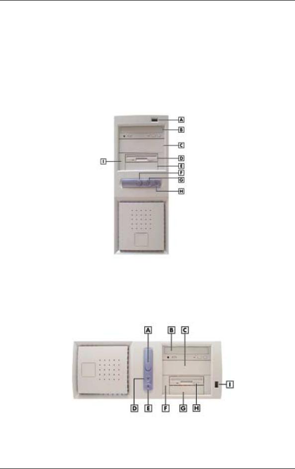
PowerMate CT Minitower Front Features
A – USB Port |
F – Power/Sleep Button |
B – CD-ROM Drive |
G – Power/Sleep Lamp |
C – 5 1/4-Inch Bay |
H – Disk Activity Lamp |
D – Diskette Drive |
I – Bracket for 3 1/2-Inch Accessible Devices |
E – 3 1/2-Inch Accessible Device Bay |
|
PowerMate CT Desktop Front Features
A – Power/Sleep Button |
F – Bracket for 3 1/2-Inch Accessible Devices |
B – CD-ROM Drive |
G – 3 1/2-Inch Accessible Device Bay |
C – 5 1/4-Inch Bay |
H – Diskette Drive |
D – Power/Sleep Lamp |
I – USB Port |
E – Disk Activity Lamp |
|
1-4 Overview

The system has the following devices, controls, and lamps at the front of the system (see the above figures for device, control, and lamp locations).
!Power/sleep button — press this button to turn on system power. To turn off power, close all applications, shut down Windows® ; Windows 98 and Windows 2000 automatically power down the system. For Windows NT® , close all applications, shut down Windows NT, and press in the power button until the system powers down (approximately four seconds).
Press and immediately release the power button to suspend system operation and go into the power saving mode. If a VESA-compliant monitor is in use, the monitor also goes into a power-saving mode.
Press any key or move the mouse to exit the power saving mode and resume system operation.
!Power/sleep lamp — indicates if system power is on or off. Also indicates if the system is operating in a power saving mode.
A steady green lamp indicates that power is on. An amber lamp and a blank screen indicates that the system is in a sleep mode with full power reduction.
!Hard drive lamp — when blinking, indicates that the hard drive is active. A blinking lamp indicates that the hard drive is reading or writing data.
!CD-ROM drive — load and start programs from a compact disc (CD) and to play audio CDs. Controls and indicators include a CD tray open button, drive activity lamp, and emergency tray open feature. Controls for an optional DVD-ROM drive are similar.
!DVD-ROM drive — DVD-ROM drives offer many improvements over the standard CD-ROM technology, including superior video and audio playback, faster data access, and greater storage capacities.
The DVD-ROM drive uses DVD technology to read DVD discs as well as standard audio and video CDs.
!CD-RW drive — use the drive to read and write data on a CD-RW disc many times, just like you would with a diskette, Zip disk, or hard drive.
!Zip drive — use the Zip drive with 3 1/2-inch Zip disks to back up work, archive old files, and transport work. The Zip drive supports both 250-MB and 100-MB Zip disks.
!Diskette drive — copy data files to and from a diskette or use as a bootable drive for loading and starting programs from a diskette. Controls and indicators include a diskette eject button and drive activity lamp.
!USB port — use this port to connect up to 127 universal serial bus (USB) devices without opening the system. A second port is on the rear of the system.
Rear Features
The rear of the system contains external connectors and ports, a system power socket, a monitor power socket, a voltage switch, expansion board slots, and security features.
The following figures show minitower and desktop features. Brief descriptions of each item follow the figure. See the next two sections for information about the connectors and the power supply. See “Expansion Boards” in Section 3 for information about expansion board slots. See “Security Features” later in this section for information on security features.
Overview 1-5
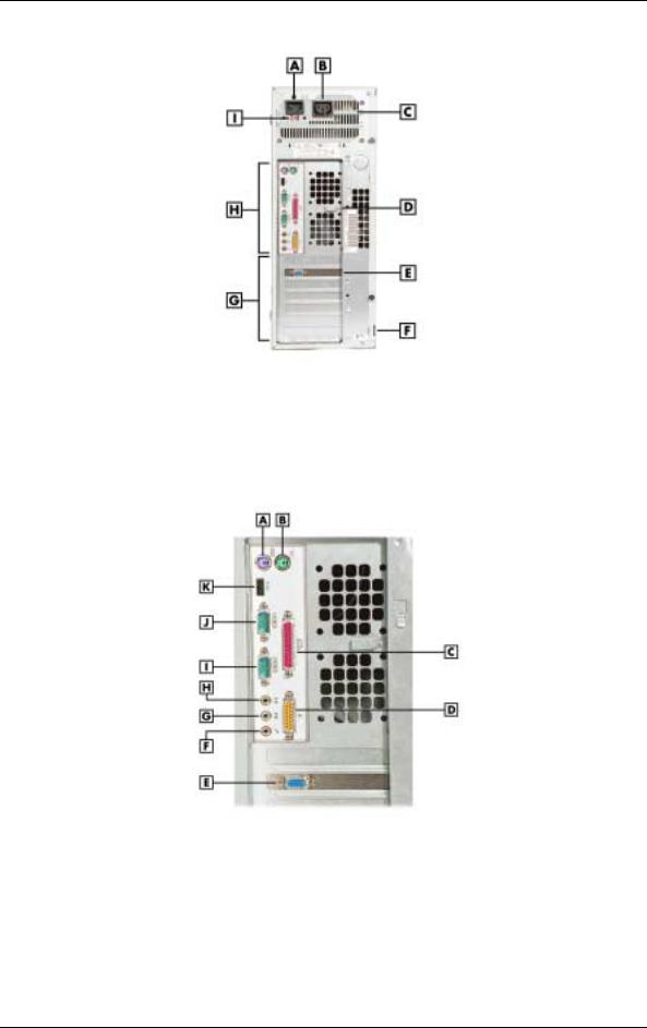
PowerMate CT Minitower Rear Features
A – AC Power Connector |
F – Locking Tab |
B – Monitor Power Socket |
G – Expansion Slots |
C – Power Supply |
H – System Board Connectors |
D – Keyboard/Mouse Anti-Theft Bracket |
I – Voltage Switch |
E – AGP Video Board |
|
Minitower Rear Connector Locations
A – Keyboard Connector |
G – Line In |
B – Mouse Connector |
H – Line Out |
C – Parallel Port |
I – Serial Port 2 |
D – MIDI/Game Port |
J – Serial Port 1 |
E – VGA Connector |
K – USB Port |
F – Microphone In |
|
1-6 Overview

PowerMate CT Desktop Rear Features
A – Power Supply |
F – System Board Connectors |
B – Keyboard/Mouse Anti-theft Bracket |
G – Monitor Power Socket |
C – AGP Video Board |
H – Voltage Switch |
D – Locking Tab |
I – AC Power Connector |
E – Expansion Slots |
|
Desktop Rear Connector Locations
A – Mouse Connector |
G – Line Out |
B – Parallel Port |
H – Serial Port 2 |
C – MIDI/Game Port |
I – Serial Port 1 |
D – VGA Connector |
J – USB Port |
E – Microphone In |
K – Keyboard Port |
F – Line In |
|
The rear of the system has the following external ports, connectors, jacks, and expansion slots.
!Keyboard port — attach a PS/2® -compatible (personal system/2-compatible) keyboard (101-key or 102-key) with a 6-pin mini DIN connector to this port.
!Mouse port — attach a PS/2-compatible mouse to this port.
!Printer port — attach a parallel printer with a 25-pin connector to this port.
!USB port — use the USB port to connect up to 127 USB configured peripheral devices such as a printer, monitor, modem, mouse, and scanner. A second USB port is on the front of the system.
!Serial ports — serial port 1 (COM1) and serial port 2 (COM2) allow connection of serial devices with 9-pin connectors. The devices include a pointing device, serial printer, or modem.
Overview 1-7
!VGA monitor connector — attach a video graphics array (VGA)-compatible monitor (NEC MultiSync® monitor or other VGA-compatible monitor) with a 15-pin connector to the AGP connector on the installed video board.
!Monitor power socket — if a plug adapter is available, connect the power cord from the monitor to the monitor power socket to use fewer wall or surge protector outlets.
!Microphone in jack — use this jack to connect a microphone for recording audio information in data system files.
!Line in jack — use this jack to connect a stereo audio device such as a stereo amplifier or a cassette or minidisc player for playback or recording.
!Line out jack — use this jack to connect an amplified output device, such as powered speakers or headset, a stereo tape recorder, or an external amplifier for audio output.
!MIDI/joystick — use this connector to attach a joystick to the system for use with games.
!Expansion board slots — use these slots to install up to five optional PCI boards (graphics, LAN, modem, sound).
Inside Features
The following figure shows the interior of the system and its major areas. A list of features follow the figure.
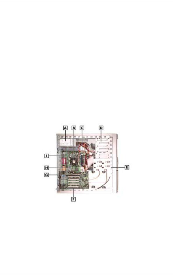
Inside the System
A – Power Supply |
F – PCI Expansion Board Connectors |
B – System Board |
G – AGP Video Board |
C – RIMM Memory Sockets |
H – AMR Connector |
D – Accessible Device Cage |
I – Processor |
E – Internal Drive Bracket |
|
1-8 Overview
The inside of the system has the following features:
!system board — contains the Pentium processor Socket 370 connector, two RIMM memory sockets, two IDE connectors, five PCI board connectors, an AGP board connector, an AMR board connector, diskette drive connector, system configuration jumpers, internal signal and power connectors, and external device connectors
!5 1/4-inch accessible device cage — has two accessible 5 1/4-inch slots for the CD-ROM drive or DVD-ROM drive and another 5 1/4-inch device
!3 1/2-inch accessible device cage — contains two accessible 3 1/2-inch slots, one of which houses the 1.44-MB diskette drive
!internal drive bracket — has three 3 1/2-inch internal device slots, one of which houses the standard hard drive
!expansion slots — provide five PCI board expansion slots, one of which houses the standard AGP video board
!235-watt power supply — is switch selectable, 115 Vac or 230 Vac.
For more information on the above features, see “Components” in this section.
Power Management Features
The system comes with Advanced Power Management (APM) and Advanced Configuration and Power Interface (ACPI). Included as a subset to ACPI is Instantly Available Technology.
APM features Soft Power Off, which automatically powers down the system when exiting Windows 98 or Windows 2000 (not available for Windows NT). This feature is enabled or disabled through the system’s BIOS (see Section 2, “System Configuration,” for Power Management BIOS settings).
Instantly Available Technology features the ACPI sleep mode which maximizes power savings. When in the sleep mode, the system appears to be off. The power supply and fans are off and the power lamp is amber. Pressing a key or moving the mouse instantly wakes up the system and returns it to where it was before going into the sleep mode. This feature is enabled or disabled by setting jumpers on the system board (see Section 2, “System Configuration” for information on setting system board jumpers).
If the system has an optional internal or external modem installed, the Wake On Ring (WOR) and Resume On Ring (ROR) features of the system can be used. With WOR, the system can be powered up through the modem from either the Soft Power Off or ACPI modes. The first call through the modem powers on the system and the second call allows access to your system.
The ROR feature allows a single call on the modem to resume system operation and to allow system access. The ROR feature can be used while the system is in the sleep mode or the ACPI power on state.
See Section 2, “System Configuration” for information on setting the WOR and ROR features through the system’s BIOS. In addition, for the WOR feature, a cable must be connected to a modem and to the WOR connector on the system board.
Overview 1-9

Software Features
NECC provides a variety of applications and hardware utilities with the system to let you take advantage of the system hardware capabilities.
Preloaded Software
The system comes preloaded with the Microsoft® Windows® 98 operating system or the Windows 2000 /Windows NT® operating system configuration.
If you have a Windows 2000/Windows NT configuration, you must choose the operating system you want to load. The operating system you choose is your only operating system and is the one that the Product Recovery Program restores.
NECC-provided applications, drivers, and utilities come loaded on the hard drive. You can install some of the applications from icons on the Windows desktop. Software available on the system includes the following applications:
!Microsoft Internet Explorer
Internet Explorer provides a top-notch browser with preloaded links for easy access to the world wide web. Also use Internet Explorer to access one of the many new browser-based utilities.
!Norton AntiVirus™ 2000 Software
Protect the system from viruses by running Norton’s virus scan software.
!Adobe® Acrobat® Reader
Use the Adobe Acrobat Reader to read and print portable document format (PDF) files found on the Internet and PDF documents included with various software applications.
!Online Documentation
Get quick access to comprehensive information about your system in the online PowerMate CT User’s Guide. See “Online Documentation” in Section 2 for a description of the documentation and how to use it.
!Intel LANDesk® Client Manager
Use LANDesk software to track system information such as serial number, BIOS version, memory capacity, disk capacity, expansion board settings, and applications. Use LANDesk software for remote starts from a server computer using Wake-On LAN and remote boot.
NEC Product Recovery Program CD
The system comes with an NEC Product Recovery Program CD and bootable diskette. Should a problem occur that causes data loss or corruption, you can use the NEC Product Recovery Program CD to restore the system to its original factory state or you can restore just the operating system and drivers. A full system restore loads the operating system and all the factory-supplied software that comes on the hard drive. See “Product Recovery Program” in Section 2 for information about using the restore options.
NEC PowerMate Driver CD
Use the NEC PowerMate Driver CD to install drivers for NEC system options that are not part of the factory configuration. Also use the NEC PowerMate Driver CD to reinstall NECC-supplied software. See “PowerMate Driver CD” in Section 2 for information about installing drivers from the CD.
1-10 Overview

Security Features
The system has hardware, software, and mechanical security features that offer protection against unauthorized access to the system and data. The following security features are available.
Password Security
The BIOS Setup Utility includes a feature that allows a user to set either a user or supervisor password, or both.
The user password controls booting of the system and controls access to the Setup Utility and the keyboard. User access to the BIOS Setup Utility is limited when a supervisor password is set. The supervisor password allows full access to the system and the BIOS.
See Section 2, “System Configuration,” for further information on setting and using passwords.
Windows Network Security Features
The Windows Network Security feature is available through the Windows operating system. Check the Windows documentation for details.
Keyboard/mouse Anti-theft Bracket
The keyboard/mouse anti-theft bracket secures the keyboard and mouse cables to the system, making it difficult to remove the keyboard and mouse from the system.
Locking Tab
The system has a locking tab on the rear of the system. The tab fits through a mating slot in the rear edge of the chassis cover. Securing a padlock (not supplied) in the locking tab prevents removal of the system cover and access to the interior of the system.
Chassis Intrusion Notification
Whenever the system cover is removed, a hidden switch (if installed) sends a signal to the LANDesk Client Manager (LDCM). LDCM logs the incident and then reports it on screen the next time the system is rebooted.
Hard Drive Password Protection
The system supports password protection for the hard drive. Hard drive password protection restricts access to the drive if the drive is removed and installed in another system. The system does not prompt for hard drive passwords while the drive remains in the current system.
The passwords are written to the system BIOS and to the hard drive to ensure that the password protection travels with the drive if it is moved to another system. See Section 2, “System Configuration,” for additional information on using hard drive security.
Overview 1-11

Components
The major system components are listed in the following table, along with the page number where each component is briefly described.
|
System Components |
|
|
Component |
Go to Page |
|
|
System Board |
1-12 |
System Memory |
1-13 |
Diskette Drive |
1-13 |
Hard Drive* |
1-13 |
AGP Video Board* |
1-13 |
Power Supply |
1-13 |
Keyboard |
1-13 |
Mouse |
1-14 |
CD-ROM Drive* |
1-14 |
DVD-ROM Drive* |
1-14 |
CD-RW Drive* |
1-14 |
Zip Drive* |
1-14 |
Speakers* |
1-14 |
Modem Board* |
1-15 |
Network Board* |
1-15 |
* Built-to-order component
System Board
The system processor, memory, system battery, internal connectors, and most external connectors are housed on the system board. For information on the external connectors, see “External Connectors” earlier in this chapter.
The system board supports one diskette drive and up to four IDE devices such as hard drives, a CD-ROM drive, a DVD-ROM drive, a CD-RW drive, or a Zip drive.
Internal connectors on the system board include:
!primary and secondary IDE connectors with Ultra DMA/66 support
!one diskette drive connector
!one processor socket
!front panel connectors for system lamps and USB
!power connectors
!two RIMM sockets
!five PCI connectors
!one AGP connector
!one AMR connector.
For further information on the system board, see Section 4, “System Boards.”
1-12 Overview

System Memory
The system supports up to 512 MB of high-speed non-ECC or ECC RDRAM memory in two RIMM sockets on the system board. Supported are 184-pin, PC800-MHz modules in
64-, 128-, and 256-MB unbuffered configurations.
The RIMM modules can be installed in one or two sockets and can vary in size between sockets. If only one RIMM module is installed, a continuity module must be installed in the empty socket.
Diskette Drive
A single diskette drive is supported in the system. The installed 1.44-MB 3 1/2-inch diskette drive is connected by a ribbon cable with two connectors. The diskette drive cable plugs directly into the system board. There are no switches or jumpers that need to be set and the diskette drive is terminated.
Diskette drive specifications are given in Section 9, “Specifications.”
Hard Drive
All systems ship with one internal 3 1/2-inch EIDE hard installed inside the system, under the CD-ROM drive. Drives are available in 10-GB or higher Ultra DMA/66 models.
An Ultra DMA/66 cable connects the hard drive to the primary IDE channel on the system board. The drive is connected as the master device on the primary channel.
Hard drive jumper settings are given in Section 2, “System Configuration.” The location of the primary IDE connector on the system board is shown in Section 4, “System Boards.” Hard drive specifications are given in Section 9, “Specifications.”
AGP Video Board
Systems ship with an AGP video board. The board has a 4x nVidia Vanta™ 3D graphics processor, 8 MB of video memory, and a VGA connector. The processor supports the AGP 4X bus, 3D graphics, and 2D graphics. It also supports video, software, and DVD playback. The system can be upgraded with an optional 32-MB 4x nVidia TnT2 Pro AGP video board.
Connect a VGA compatible monitor to the VGA connector on the AGP video board.
Power Supply
The 235-watt power supply is mounted inside the system unit. It supplies power to the system board, option boards, diskette drive, hard drives, CD-ROM or other drives, keyboard, mouse, and other internal options. A fan inside the power supply provides system cooling.
Power supply connector locations on the system board are given in Section 4, “System Board.” Power supply specifications are given in Section 9, “Specifications.”
Keyboard
The PS/2-compatible ergodynamic keyboard is standard equipment for the system. The keyboard provides a numeric keypad, separate cursor control keys, 12 function keys, and is capable of up to 48 functions. Key status lamps on the keyboard include Num (Numeric) Lock, Caps (Capital) Lock, and Scroll Lock.
The keyboard’s six-pin connector plugs into the back of the system. Keyboard specifications are given in Section 9, “Specifications.”
Overview 1-13

Mouse
The system ships with a PS/2-compatible mouse as standard equipment. The mouse has a self-cleaning mechanism that prevents a buildup of dust or lint around the mouse ball and tracking mechanism.
The six-pin mouse cable connector plugs into the back of the system. Mouse specifications are given in Section 9, “Specifications.”
CD-ROM Drive
Some systems come with a 40X or higher CD-ROM drive. The drive features up to 40-speed or higher technology, affording faster data transfer and smoother animation and video. The CDROM drive comes with an Enhanced IDE (EIDE) interface. The drive is fully compatible with Kodak Multisession Photo CDs™ , CD-I, FMV, and CD Plus, as well as standard CDs. The CDROM drive can also play audio CDs (for systems with sound capabilities).
An IDE cable connects the CD-ROM drive to the secondary IDE channel on the system board. The drive is connected as the master device on the secondary channel.
CD-ROM jumper settings are included in Section 2, “System Configuration.” Specifications for the CD-ROM drive are given in Section 9, “System Specifications.”
DVD-ROM Drive
Some systems come with an 12X or higher DVD-ROM drive. The drive offers many improvements over the standard CD-ROM, including superior video and audio playback, faster data access, and greater storage capabilities.
An IDE cable connects the DVD-ROM drive to the secondary IDE channel on the system board. The drive is connected as the master device on the secondary channel.
DVD-ROM jumper settings are included in Section 2, “System Configuration.” Specifications for the DVD-ROM drive are given in Section 9, “System Specifications.”
CD-RW Drive
Some systems come with an 8x4x32x (8x record, 4x rewrite, 32x read) compact diskReWritable (CD-RW) drive. Use the drive to record data on a CD-RW disc, just like you would on a diskette, Zip® disk, or hard drive.
Zip Drive
Some systems come with a 250-MB capacity internal ATAPI Zip® drive. Connect the Zip drive to one of the IDE connectors. Use the Zip drive with 3 1/2-inch Zip disks to back up work, archive old files, and transport work. The Zip drive supports both 250-MB and 100-MB Zip disks.
Speakers
Some systems come with a high-quality 10-watt stereo speaker set, an AC adapter, and connecting cables. If the speaker set has a volume control, adjust the speaker volume by using this control. Volume can also be controlled by the Windows sound software. The speaker set connects to the speaker line out jack on the back of the system. Speaker specifications are given in Section 9, “Specifications.”
1-14 Overview

Modem Board
Some systems come with a V.90 rated 56-kilobits per second (Kbps) PCI modem board. The modem board allows the connection of a phone line to the system for data communications functions.
Network Board
Some systems might come with a 10/100 network board installed in a PCI slot. Specifications for the network board are given in Section 9, “Specifications.”
Overview 1-15

2
System Configuration
!Interrupt Requests
!Jumper Settings
!BIOS Setup Utility
!Hard Drive Security
!FLASH Utility
!Online Documentation
!Product Recovery Program
!PowerMate Driver CD
!Intel Processor Serial Number Control Utility

This section provides information for configuring the system. The section includes:
!system interrupt request (IRQ) assignments
!system jumper settings
!procedures for using the Phoenix® Technologies Ltd. BIOS Setup Utility to configure the system
!description and procedures for using hard drive security for password protection of the hard drive
!descriptions and procedures for using the following utilities and applications
—FLASH Utility
—Online Documentation
—Product Recovery Program
—PowerMate Driver CD
—Intel Processor Serial Number Control Utility.
Interrupt Requests
The following paragraphs list the system interrupts (IRQs), parallel interrupts, and serial interrupts. See Section 4, “System Board,” for parallel and serial addresses. For Windows 98 and Windows 2000, a listing of hardware resources is available on the system. Click Start, point to Programs, Accessories, and System Tools, and click System Information.
System Interrupts
The system has 16 IRQs (IRQ 0 through 15) assigned to different devices (for example, printer, modem, keyboard, mouse). Initial IRQ settings are assigned at the factory, with settings dependent on the installed device(s). See “BIOS Setup Utility” in this section for information on using the utility to assign or change the interrupts.
The following table lists the IRQ settings. Assignments 0 through 15 are in order of decreasing priority.
|
Interrupt Level Assignments |
|
|
Interrupt |
|
Priority |
Interrupt Device* |
|
|
IRQ00 |
System Timer |
IRQ01 |
Standard 101/102 or MS Natural Keyboard |
IRQ02 |
Programmable Interrupt Controller |
IRQ03 |
Communications Port (COM2) |
IRQ04 |
Communications Port (COM1) |
IRQ05 |
MPU-401 Compatible |
IRQ06 |
Standard Floppy Disk Controller |
IRQ07 |
ECP Printer (LPT 1) |
* IRQ settings may vary, depending on system configuration.
2-2 System Configuration

|
Interrupt Level Assignments |
|
|
Interrupt |
|
Priority |
Interrupt Device* |
|
|
IRQ08 |
System CMOS/real time clock |
IRQ09 |
Shared Resource: ACPI IRQ Holder for PCI IRQ |
|
Steering/YAMAHA AC-XG Audio Device/Intel |
|
82801AA SMBus Controller/SCI IRQ used by |
|
ACPI bus |
IRQ10 |
Shared Resource: ACPI IRQ Holder for PCI IRQ |
|
Steering/Winfast 3D S32011 (TNT2-PRO) |
IRQ11 |
Shared Resource: ACPI IRQ Holder for PCI IRQ |
|
Steering/Intel 82801AA USB Universal Host |
|
Controller |
IRQ12 |
WheelMouse (PS/2) |
IRQ13 |
Numeric Data Processor |
IRQ14 |
Primary IDE Controller/Intel 82801AA Bus |
|
Master IDE Controller |
IRQ15 |
Secondary IDE Controller |
* IRQ settings may vary, depending on system configuration.
Parallel Port Interrupts
The parallel port I/O interrupts are given in the following table.
|
Parallel Port Interrupts |
|
|
Port |
Interrupt |
|
|
LPT1 |
IRQ07 |
LPT2 |
IRQ07 |
LPT3 |
IRQ07 |
|
|
System Configuration 2-3
Loading...