


User’s Manual/ Manuel de l’utilisateur/ Manual del Usuario
MultiSync LCD2070NX
MultiSync LCD2170NX
MultiSync LCD2070VX

Index |
|
Warning................................................................................................................................................................. |
1 |
Contents............................................................................................................................................................... |
2 |
Display Setup....................................................................................................................................................... |
3 |
Mounting............................................................................................................................................................... |
8 |
Flexible Arm Installation................................................................................................................................. |
10 |
Controls............................................................................................................................................................... |
12 |
Recommended Use............................................................................................................................................ |
15 |
Specifications.................................................................................................................................................... |
17 |
Features............................................................................................................................................................. |
20 |
Troubleshooting................................................................................................................................................ |
21 |
Advanced Menu ................................................................................................................................................ |
22 |
References.......................................................................................................................................................... |
23 |
Limited Warranty............................................................................................................................................. |
24 |
TCO’03.................................................................................................................................................................. |
25 |
Manufacturer’s Recycling and Energy Information ............................................................................... |
26 |
Avertissement ................................................................................................................................................ |
28 |
Contenu.............................................................................................................................................................. |
29 |
Configuration de I’affichage.......................................................................................................................... |
30 |
Montage.............................................................................................................................................................. |
35 |
Installation du bras flexible .......................................................................................................................... |
37 |
Commandes........................................................................................................................................................ |
39 |
Usage recommandé......................................................................................................................................... |
42 |
Fiche technique................................................................................................................................................ |
45 |
Fonctions........................................................................................................................................................... |
48 |
Dépannage......................................................................................................................................................... |
49 |
Menu Advancé .................................................................................................................................................. |
50 |
Références.......................................................................................................................................................... |
51 |
Garantie limitée................................................................................................................................................ |
52 |
TCO’03.................................................................................................................................................................. |
53 |
Informations du fabricant relatives au recylage et aux économies d’énergie ............................... |
54 |
Advertencia....................................................................................................................................................... |
57 |
Contenidos........................................................................................................................................................ |
58 |
Instalación de la pantalla.............................................................................................................................. |
59 |
Montaje.............................................................................................................................................................. |
64 |
Instalación de brazos flexibles..................................................................................................................... |
66 |
Controles........................................................................................................................................................... |
68 |
Uso recomendado............................................................................................................................................. |
71 |
Especificaciones................................................................................................................................................ |
73 |
Características.................................................................................................................................................. |
76 |
Solución de problemas..................................................................................................................................... |
77 |
Menú avanzado.................................................................................................................................................. |
78 |
Referencias........................................................................................................................................................ |
79 |
Garantía limitada............................................................................................................................................. |
80 |
TCO’03.................................................................................................................................................................. |
81 |
Información del fabricante sobre reciclado y energía........................................................................... |
82 |

WARNING
TO PREVENT FIRE OR SHOCK HAZARDS, DO NOT EXPOSE THIS UNIT TO RAIN OR MOISTURE. ALSO, DO NOT USE THIS UNIT’S POLARIZED PLUG WITH AN EXTENSION CORD RECEPTACLE OR OTHER OUTLETS UNLESS THE PRONGS CAN BE FULLY INSERTED.
REFRAIN FROM OPENING THE CABINET AS THERE ARE HIGH VOLTAGE COMPONENTS INSIDE. REFER SERVICING TO QUALIFIED SERVICE PERSONNEL.
CAUTION
CAUTION: TO REDUCE THE RISK OF ELECTRIC SHOCK, MAKE SURE POWER CORD IS UNPLUGGED FROM WALL SOCKET. TO FULLY DISENGAGE THE POWER TO THE UNIT, PLEASE DISCONNECT THE POWER CORD FROM THE AC OUTLET. DO NOT REMOVE COVER (OR BACK). NO USER SERVICEABLE PARTS INSIDE. REFER SERVICING TO QUALIFIED SERVICE PERSONNEL.
This symbol warns user that uninsulated voltage within the unit may have sufficient magnitude to cause electric shock. Therefore, it is dangerous to make any kind of contact with any part inside this unit.
This symbol alerts the user that important literature concerning the operation and maintenance of this unit has been included. Therefore, it should be read carefully in order to avoid any problems.
Canadian Department of Communications Compliance Statement
DOC: This Class B digital apparatus meets all requirements of the Canadian Interference-Causing Equipment Regulations.
C-UL: Bears the C-UL Mark and is in compliance with Canadian Safety Regulations according to CAN/CSA C22.2 No. 60950-1.
FCC Information
1.Use the attached specified cables with the MultiSync® LCD2070NX™ (L204FY), LCD2170NX™ (L215GA), and LCD2070VX™ (L204FY) color monitors so as not to interfere with radio and television reception.
(1)Please use the supplied power cord or equivalent to ensure FCC compliance.
(2)Please use the supplied shielded video signal cable. Please use the supplied USB cable with ferrite cores.
Use of other cables and adapters may cause interference with radio and television reception.
2.This equipment has been tested and found to comply with the limits for a Class B digital device, pursuant to part 15 of the FCC Rules. These limits are designed to provide reasonable protection against harmful interference in a residential installation. This equipment generates, uses, and can radiate radio frequency energy, and, if not installed and used in accordance with the instructions, may cause harmful interference to radio communications. However, there is no guarantee that interference will not occur in a particular installation. If this equipment does cause harmful interference to radio or television reception, which can be determined by turning the equipment off and on, the user is encouraged to try to correct the interference by one or more of the following measures:
• Reorient or relocate the receiving antenna.
• Increase the separation between the equipment and receiver.
• Connect the equipment into an outlet on a circuit different from that to which the receiver is connected.
• Consult your dealer or an experienced radio/TV technician for help.
If necessary, the user should contact the dealer or an experienced radio/television technician for additional suggestions. The user may find the following booklet, prepared by the Federal Communications Commission, helpful: ”How to Identify and Resolve Radio-TV Interference Problems.“ This booklet is available from the U.S. Government Printing Office, Washington, D.C., 20402, Stock No. 004-000-00345-4.

Contents
Your new NEC MultiSync® LCD monitor box* should contain the following:
•MultiSync LCD monitor with height adjustable stand
•Power Cord
•Cable Management Cover
•Video Signal Cable (mini D-SUB 15 pin to mini D-SUB 15 pin)
•Video Signal Cable (DVI-D to DVI-D)
•USB Cable (LCD2070NX & LCD2170NX)
•User’s Manual
Power Cord
Cable Management Cover
Mini D-SUB Cable
USB Cable |
|
|
|
DVI-D Cable |
|
|
|
||
(LCD2070NX& |
|
|
|
|
|
|
|
|
|
LCD2170NX) |
|
|
|
User’s Manual |
|
|
|
||
|
|
|
|
*Remembertosaveyouroriginalboxandpackingmaterialtotransportorshipthemonitor.
Display Setup
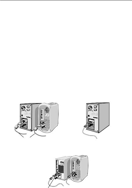
To attach the MultiSync® LCD monitor to your system:
1.Turn off the power to your computer.
2.ForthePCorMACwithDVIdigitaloutput:ConnecttheDVIsignalcableto the connector of the display card in your system (Figure 1). Tighten all screws.
For the PC with Analog output: Connect the 15-pin mini D-SUB signal cable to the connector of the display card in your system (Figure 2). Tighten all screws.
For MAC setup: Connect the Macintosh cable adapter to the computer, then attach the 15-pin mini D-SUB signal cable to the Macintosh cable adapter (Figure 3). Tighten all screws.
NOTE: To obtain the MultiSync Macintosh cable adapter, call NEC Display Solutions of America, Inc. at (800) 632-4662.
Figure 1 |
|
Figure 2 |
|
|
|
|
|
|
DVI Signal Cable
Figure 3
Macintosh Cable Adapter (not included)
Note: Some Macintosh systems do not require a Macintosh Cable Adapter

Display Setup - continued
3.Place hands on each side of the monitor to tilt the LCD panel 30degree angle and lift up to the highest position (Figure 4).
4.Connect all cables to the appropriate connectors (Figure 4).
NOTE: If connecting both DVI and D-sub cable, the DVI cable must be connected along side the rib on the power cord side (Figure 4).
5.For successful cable management, place the cables in this order into the cable management: power cable and DVI cable (Figure 5).
6.Place DVI cable and power cable into the specific hooks indicated in (Figure 6).
30˚ Tilt
Figure 4
(Pictured: LCD2070NX)
Highest
Stand
Position
 DVI Cable Input2(D-Sub)
USB (NX models only)
Input1(DVI) 


Power cord
DC-OUT
NEC optional product atttachment.
Do not use this connector unless specified.
Figure 5
(Pictured: LCD2070NX)
DVI Cable 

 (Top)
(Top)
Power Cable (Bottom) 
Figure 6 |
|
(Pictured: LCD2070NX) |
D-SUB Cable |
USB Cable
(NX models only)
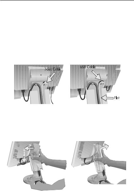
Display Setup - continued
7.Place the D-Sub and the USB cable into the specific hooks indicated in (Figure 7). USB cable is used with NX models only.
8.Make sure all cables are resting flat against the stand (Figure 7).
9.Hold the all cables firmly and place the cable cover onto the stand (Figure 8). To remove the cable cover, lift the cover off as shown in (Figure 9).
Figure 7
(Pictured: LCD2070NX)
(NX models only)
|
|
|
|
Figure 8 |
|
|
|
Figure 9 |
|||||||
|
|
|
|
|
|
|
|
|
|
|
|
|
|
|
|
|
|
|
|
|
|
|
|
|
|
|
|
|
|
|
|
|
|
|
|
|
|
|
|
|
|
|
|
|
|
|
|
|
|
|
|
|
|
|
|
|
|
|
|
|
|
|
|
|
|
|
|
|
|
|
|
|
|
|
|
|
|
|
|
|
|
|
|
|
|
|
|
|
|
|
|
|
|
|
|
|
|
|
|
|
|
|
|
|
|
|
|
|
|
|
|
|
|
|
|
|
|
|
|
|
|
|
|
|
|
|
|
|
|
|
|
|
|
|
|
|
|
|
|
|
|
|
|
|
|
|
|
|
|
|
|
|
|
|
|
|
|
|
|
|
|
|
|
|
|
|
|
|
|
|
|
|
|
|
|
|
|
|
|
|
|
|
|
|
|
|
|
|
|
|
|
|
|
|
|
|
|
|
|
|
|
|
|
|
|
|
|
Display Setup - continued
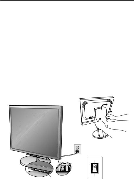
10.Connect the power cord to the power outlet (Figure 10).
NOTE: If you have difficulty removing the cable cover, please push the the cover up (towards the top of the monitor) in order to unhook the cover from the stand, then remove, as shown in (Figure 11). Handle with care when removing cable cover.
NOTE: If you use this monitor at AC125-240V, please refer to Recommended Use section of this manual for proper selection of power cord.
11.The vacation switch on the back side of the monitor must be turned on (Figure 10). Turn on the monitor with the front power button and the computer.
NOTE: The vacation switch is a true on/off switch. If this switch is on the OFF position, the monitor cannot be turned on using the front button. DO NOT switch on/off repeatedly.
Figure 11
Figure 10
Vacation |
OFF Position |
Switch |
|
Power Button |
ON Position |

Display Setup - continued
12.Analog input only: No-Touch Auto Adjust automatically adjusts the monitor to optimal settings upon initial setup for most timings. For further adjustments, use the following OSM® controls:
• Auto Adjust Contrast • Auto Adjust
Refer to the Controls section of this User ’s Manual for a full description of these OSM controls.
NOTE: For download information on the Windows® 95/98/ Me/2000/XP INF file for your monitor, refer to the References section of this User’s Manual.
NOTE: If you have any problems, please refer to the Troubleshooting section of this User’s Manual.
Raise and Lower Monitor Screen
The monitor may be raised or lowered. To raise or lower screen, place hands on each side of the monitor and lift or lower to the desired height (Figure RL.1).
NOTE: Handle with care when raising or lowering the monitor screen.
Figure RL.1
Tilt and Swivel
Grasp both sides of the monitor screen with your hands and adjust the tilt and swivel as desired (Figure TS.1).
NOTE: Handle with care when tilting and swiveling the monitor screen.
Figure TS.1
Mounting - LCD2070NX,LCD2070VX
Remove Monitor Stand for Mounting
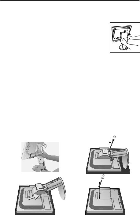
To prepare the monitor for alternate mounting method:
1.Place hands on each side of the monitor and lift up to the highest position. Remove the cable cover (Figure
M.1). |
|
NOTE: If you have difficulty removing the cable cover, |
|
push the the cover up (towards the top of the monitor) |
|
in order to unhook the cover from the stand, then |
|
remove, as shown in (Figure). Handle with care when |
|
removing cable cover. |
Figure |
2.Disconnect all cables.
3.Place monitor face down on a non-abrasive surface (Figure M.2).
NOTE: Handle with care when the monitor is facing down to avoid damaging the front buttons.
4.Remove the 2 screws connecting the stand to the monitor (Figure M.2).
5.Lift up the stand to unlatch the upper hooks and remove the stand (Figure M.3).
6.Remove the 2 screws on the top of the monitor (Figure M.4). The monitor is now ready for mounting in an alternate manner.
7.Connect the cables to the back of the monitor.
8.Reverse this process to reattach stand.
NOTE: Use only VESA-compatible alternative mounting method. Handle with care when removing stand. 
Figure M.2
Figure M.1

 Figure M.4
Figure M.3
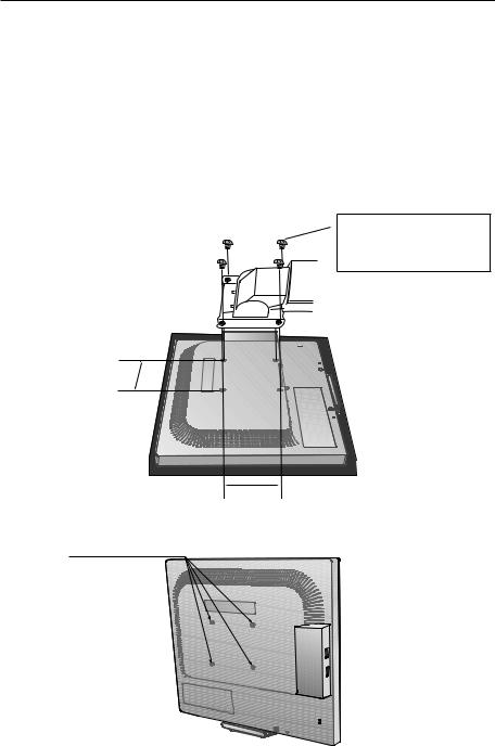
Mounting - LCD2170NX
Remove Monitor Stand for Mounting
To prepare the monitor for alternate mounting method:
1.Place hands on each side of the monitor and lift up to the highest position. Remove the cable cover (Figure
M.1). |
|
NOTE: If you have difficulty removing the cable cover, |
|
push the the cover up (towards the top of the monitor) |
|
in order to unhook the cover from the stand, then |
|
remove, as shown in (Figure). Handle with care when |
|
removing cable cover. |
Figure |
2.Disconnect all cables.
3.Place monitor face down on a non-abrasive surface (Figure M.2).
NOTE: Handle with care when the monitor is facing down to avoid damaging the front buttons.
4.Remove the 4 screws connecting the stand to the monitor (Figure M.2).
5.Remove the stand (Figure M.3).
6.Connect the cables to the back of the monitor.
7.Reverse this process to reattach stand.
NOTE: Use only VESA-compatible alternative mounting method. Handle with care when removing stand.
Figure M.2
Figure M.1
Figure M.3

Flexible Arm Installation - LCD2070NX,LCD2070VX
This LCD monitor is designed for use with a flexible arm. To mount the monitor to a flexible arm:
1.Follow the instructions on how to Remove Monitor Stand for Mounting to remove the stand.
2.Using the 4 screws from the stand removal and attach the arm to the monitor (Figure F.1).
NOTE: The LCD monitor should only be used with an approved arm (e.g. GS mark). To meet the safety requirements, the monitor must be mounted to an arm which guaranties the necessary stability under consideration of the weight of the monitor.
|
NOTE: Please use the screws |
||
|
(4pcs) that were removed from |
||
|
stand |
when mounting flexible |
|
|
arm. |
|
|
Figure F.1 |
Thickness of Bracket (Arm) |
||
2.0~3.2mm |
|||
|
|||
100mm |
|
|
|
100mm
4 Screws (4M) (Max Depth: 14 mm)
Weight of LCD assembly:
LCD2070NX: 5.7 kg MAX
LCD2070VX: 5.8 kg MAX
(Pictured: LCD2070NX)
10
Flexible Arm Installation - LCD2170NX
This LCD monitor is designed for use with a flexible arm. To mount the monitor to a flexible arm:
1.Follow the instructions on how to Remove Monitor Stand for Mounting to remove the stand.
2.Use the 4 screws from the stand removal and attach the arm to the monitor (Figure F.1).
NOTE: The LCD monitor should only be used with an approved arm (e.g. GS mark). To meet the safety requirements, the monitor must be mounted to an arm which guaranties the necessary stability under consideration of the weight of the monitor.
Figure F.1
 2.0~3.2mm
100mm
100mm
4 Screws (4M) (Max Depth: 14 mm)
Weight of LCD assembly: 6.4 kg MAX
11
Controls
OSM® (On-Screen Manager) control buttons on the front of the monitor function as follows:
To access OSM menu, press any of the control buttons (MENU/EXIT, Left, Right, Down, Up).
To change signal input, press the SELECT button.
NOTE: OSM must be closed in order to change signal input.
Button |
Menu |
MENU/EXIT |
Exits the OSM controls. |
|
Returns to the OSM main menu. |
Left/Right |
Moves the highlighted area left/right to |
|
select control menus. |
|
Moves the bar left/right to increase or decrease the |
|
adjustment. |
|
|
Down/Up |
Moves the highlighted area down/up to select one of |
|
the controls. |
|
|
SELECT |
Active Auto Adjust function. Enter the OSM sub |
|
menu. |
RESET/DV MODE (LCD2070NX, LCD2170NX) |
Resets the highlighted control menu to the factory |
RESET (LCD2070VX) |
setting. |
Enter the DV MODE. (NX models only) |
NOTE: When reset is pressed in the main and sub-menu, a warning window will appear allowing you to cancel the reset function by pressing the MENU/EXIT button.
Brightness/Contrast Controls
BRIGHTNESS
Adjusts the overall image and background screen brightness.
CONTRAST
Adjusts the image brightness in relation to the background.
AUTO Contrast (Analog input only)
Adjusts the image displayed to optimal settings.
DV MODE (LCD2070NX, LCD2170NX only)
Allows you to select the suitable setting for Movie, Picture , etc.
Auto Adjust (Analog input only)
Automatically adjusts the Image Position, H. Size and Fine settings.
12
Controls - continued
Image Controls (Analog input only)
LEFT / RIGHT
Controls Horizontal Image Position within the display area of the LCD. DOWN / UP
Controls Vertical Image Position within the display area of the LCD. H.SIZE
Adjust this setting to increase or decrease the horizontal size. FINE
Adjust this setting to improve focus, clarity, and image stability.
AccuColor® Control Systems
AccuColor® Control Systems: Six color presets select the desired color setting (sRGB and NATIVE color presets are standard and cannot be changed).
R,G,B: Increases or decreases Red, Green or Blue color depending upon which is selected. The change in color will appear on screen and the direction (increase or decrease) will be shown by the bars.
NATIVE: Original color presented by the LCD panel that is unadjustable. sRGB: sRGB mode dramatically improves the color fidelity in the desktop environment by a single standard RGB color space. With this color supported environment, the operator could easily and confidently communicate color without further color management overhead in the most common situations.
Tools
SHARPNESS (LCD2070VX/LCD2170NX): This function allows the adjustment of the crispness of the displayed image at any time. The image can be as distinct or as soft as the user prefers. The amount of image adjustment is different depending on whether EXPANSION Mode is set to OFF, FULL or ASPECT.
EXPANSION MODE (LCD2070VX/LCD2170NX): Sets the zoom method.
FULL: The image is expanded to 1600 x 1200, regardless of the resolution. ASPECT: The image is expanded without changing the aspect ratio.
OFF: The image is not expanded.
OFF TIMER: Monitor will automatically power-down when the end user has selected a predetermined amount of time.
HOT KEY: You can adjust the brightness and contrast directly. When this function is set to ON, you can adjust the brightness with left or right control and contrast with up or down control while the OSM menu is off.
FACTORY PRESET: Selecting Factory Preset allows you to reset all OSM control settings back to the factory settings. The RESET button will need to be held down for several seconds to take effect. Individual settings can be reset by highlighting the control to be reset and pressing the RESET button.
13

Controls - continued
Menu Tools
LANGUAGE: OSM® control menus are available in eight languages. OSM LEFT/RIGHT: You can choose where you would like the OSM control image to appear horizontally on your screen.
OSM DOWN/UP: You can choose where you would like the OSM control image to appear vertically on your screen.
OSM Turn Off: The OSM control menu will stay on as long as it is in use. In the OSM Turn Off submenu, you can select how long the monitor waits after the last touch of a button to shut off the OSM control menu.
OSM Lock Out: This control completely locks out access to all OSM control functions except Brightness and Contrast. When attempting to activate OSM controls while in the Lock Out mode, a screen will appear indicating the OSM controls are locked out. To activate the OSM Lock Out function, press SELECT, then right control button and hold down simultaneously. To deactivate the OSM Lock Out, press SELECT, then left control button and hold down simultaneously while in the OSM menu.
RESOLUTION NOTIFIER: If this option is ON, a message will appear on the screen after 30 seconds notifying the user that the optimal resolution is not being used. The optimal resolution is 1600 x 1200.
Information
The Information menu indicates the current input, display resolution, horizontal and vertical frequency, and polarity settings of the monitor. The model and serial numbers of your monitor are also indicated.
OSM® Warning: OSM Warning menus disappear with Exit button.
NO SIGNAL: This function gives a warning when there is no signal present. After power is tuned on or when there is a change of input signal or video is inactive, the No Signal window will appear.
RESOLUTION NOTIFIER: This function gives a warning if a resolution other than the optimal resolution is used. After power is turned on or when there is a change of input signal or the video signal doesn’t have proper resolution, the Resolution Notifier window will open. This function can be disabled in the Menu Tools.
OUT OF RANGE: This function gives a recommendation of the optimized resolution and refresh rate. After the power is turned on or there is a change of input signal or the video signal doesn’t have proper timing, the Out Of Range menu will appear.
• For Advanced Menu options for the LCD2170NX only see page 22.
14
Recommended Use
Safety Precautions and Maintenance
FOR OPTIMUM PERFORMANCE, PLEASE NOTE
THE FOLLOWING WHEN SETTING UP AND USING
THE MULTISYNC® LCD COLOR MONITOR:
•DO NOT OPEN THE MONITOR. There are no user serviceable parts inside and opening or removing covers may expose you to dangerous shock hazards or other risks. Refer all servicing to qualified service personnel.
•Do not spill any liquids into the cabinet or use your monitor near water.
•Do not insert objects of any kind into the cabinet slots, as they may touch dangerous voltage points, which can be harmful or fatal or may cause electric shock, fire or equipment failure.
•Do not place any heavy objects on the power cord. Damage to the cord may cause shock or fire.
•Do not place this product on a sloping or unstable cart, stand or table, as the monitor may fall, causing serious damage to the monitor.
•When operating the MultiSync LCD monitor with its AC 125-240V power supply, use a power supply cord that matches the power supply voltage of the AC power outlet being used. The power supply cord you use must have been approved by and comply with the safety standards of your country. (Type H05VV-F should be used in Europe)
•In UK, use a BS-approved power cord with molded plug having a black (5A) fuse installed for use with this monitor. If a power cord is not supplied with this monitor, please contact your supplier.
•Do not place any objects onto the monitor and do not use the monitor outdoors.
•The inside of the flourescent tube located within the LCD monitor contains mercury. Please follow the bylaws or rules of your municipality to dispose of the tube properly.
•Do not bend power cord.
•Do not use monitor in high temperatured, humid, dusty, or oily areas.
•Do not cover vent on monitor.
Immediately unplug your monitor from the wall outlet and refer servicing to qualified service personnel under the following conditions:
• When the power supply cord or plug is damaged.
• If liquid has been spilled, or objects have fallen into the monitor.
• If the monitor has been exposed to rain or water.
• If the monitor has been dropped or the cabinet damaged.
• If the monitor does not operate normally by following operating instructions.
• If glass is broken, handle with care.
• If monitor or glass is broken, do not come in contact with the liquid crystal and handle with care.
• Allow adequate ventilation around the monitor so that heat can properly dissipate. Do not block ventilated openings or place the monitor near a radiator or other heat sources. Do not put anything on top of monitor.
• The power cable connector is the primary means of detaching the system from the CAUTION power supply. The monitor should be installed close to a power outlet which is easily accessible.
• Handle with care when transporting. Save packaging for transporting.
Image Persistence
Please be aware that LCD Technology may experience a phenomenon known as Image Persistence. Image Persistence occurs when a residual or “ghost” image of a previous image remains visible on the screen. Unlike CRT monitors, LCD monitors’ image persistence is not permanent, but constant images being displayed for a long period of time should be avoided.
To alleviate image persistence, turn off the monitor for as long as the previous image was displayed. For example, if an image was on the monitor for one hour and a residual image remains, the monitor should be turned off for one hour to erase the image.
As with all personal display devices, NEC DISPLAY SOLUTIONS recommends displaying moving images and using a moving screen saver at regular intervals whenever the screen is idle or turning off the monitor when not in use.
15

Recommended Use - continued
CORRECT PLACEMENT AND ADJUSTMENT OF THE MONITOR
CAN REDUCE EYE, SHOULDER AND NECK FATIGUE.
CHECK THE FOLLOWING WHEN YOU POSITION THE MONITOR:
•For optimum performance, allow 20 minutes for warm-up.
•Adjust the monitor height so that the top of the screen is at or
slightly below eye level. Your eyes should look slightly downward when viewing the middle of the screen.
• Position your monitor no closer than 16 inches and no further away than 28 inches from your eyes. The optimal distance is
20inches.
•Rest your eyes periodically by focusing on an object at least
20feet away. Blink often.
•Position the monitor at a 90° angle to windows and other light sources to minimize glare and reflections. Adjust the monitor tilt so that ceiling lights do not reflect on your screen.
•If reflected light makes it hard for you to see your screen, use an anti-glare filter.
•Adjust the monitor’s brightness and contrast controls to enhance readability.
•Use a document holder placed close to the screen.
•Position whatever you are looking at most of the time (the screen or reference material) directly in front of you to minimize turning your head while you are typing.
•Get regular eye checkups.
Ergonomics
To realize the maximum ergonomics benefits, we recommend the following:
•Use the preset Size and Position controls with standard signals
•Use the preset Color Setting
•Use non-interlaced signals with a vertical refresh rate between 60-85Hz
•Do not use primary color blue on a dark background, as it is difficult to see and
may produce eye fatigue to insufficient contrast.
For more detailed information on setting up a healthy work environment, write the American National Standard for Human Factors Engineering of Visual Display Terminal Workstations – ANSI-HFS Standard No. 100-1988 – The Human Factors Society, Inc. P.O. Box 1369, Santa Monica, California 90406.
Cleaning the LCD Panel
•When the liquid crystal panel becomes dusty or dirty, please wipe gently with soft cloth.
•Please do not rub the LCD panel with hard material.
•Please do not apply pressure to the LCD surface.
•Please do not use OA cleaner. OA cleaner will cause deterioration or discolor the LCD surface.
Cleaning the Cabinet
•Unplug the power supply
•Gently wipe the cabinet with a soft cloth
•To clean the cabinet, dampen the cloth with a neutral detergent and water, wipe the cabinet and follow with a dry cloth.
NOTE: Many plastics are used on the surface of the cabinet. DO NOT clean with benzene, thinner, alkaline detergent, alcoholic system detergent, glass cleaner, wax, polish cleaner, soap powder, or insecticide. Do not touch rubber or vinyl to the cabinet for a long time. These types of fluids and fabrics can cause the paint to deteriorate, crack or peel.
16

|
|
|
|
Specifications |
Monitor |
|
MultiSync® |
|
|
Specifications |
LCD2070NX |
Notes |
||
LCD Module |
Diagonal : |
20.1 inch |
|
Active matrix; thin film transistor (TFT) |
|
Viewable Image Size : |
20.1 inch |
|
liquid crystal display (LCD); 0.255 mm |
|
Native Resolution |
|
|
dot pitch; 250cd/m2 white luminence; |
|
(Pixel Count) : |
1600 x1200 |
700:1 contrast ratio, typical |
|
|
|
|
|
|
Input Signal |
Video : |
ANALOG 0.7 Vp-p/75 Ohms |
Digital Input: DVI-D |
|
|
Sync : |
Separate sync. TTL Level Positive/Negative |
|
|
|
|
Composite sync. Positive/Negative |
|
|
|
|
Composite Sync on Green (0.3Vp-p nega- |
|
|
|
|
tive and 0.7Vp-p positive) |
|
|
|
|
|
|
|
Display Colors |
|
16,777,216 |
Dependent on display card used. |
|
|
|
|
|
|
Maximum Viewing |
Left/Right : |
88°/88° |
(CR>10) |
|
Angles |
Up/Down : |
88°/88° |
(CR>10) |
|
|
|
|
|
|
Synchronization |
Horizontal : |
31.5 kHz to 91.1 kHz |
Automatically |
|
Range |
Vertical : |
56.0 Hz to 85.0 Hz |
Automatically |
|
|
|
|
|
|
Resolutions |
|
720 x 400*1 :VGA text |
Some systems may not support all |
|
Supported |
|
640 x 480*1 @ 60 Hz to 85 Hz |
modes listed. |
|
|
|
800 x 600*1 @ 56 Hz to 85 Hz |
|
|
|
|
832 x 624*1 @ 75 Hz |
|
|
|
|
1024 x 768*1 @ 60 Hz to 85 Hz |
|
|
|
|
1152 x 864*1 @ 75 Hz |
|
|
|
|
1152 x 870*1 @ 75 Hz |
NEC DISPLAY SOLUTIONS |
|
|
|
1280 x 960 @*1 @ 75 Hz |
cites recommended resolution |
|
|
|
1280 x 1024*1 @ 60 Hz to 85 Hz |
at 60 Hz for optimal display |
|
|
|
1600 x 1200 @ 60 Hz......................... performance. |
||
|
|
|
|
|
Active Display Area |
Horizontal : |
408 mm/16.1 inches |
|
|
|
Vertical : |
306 mm/12.0 inches |
|
|
|
|
|
|
|
USB Hub |
I/P : |
USB Specification Revision 2.0 |
|
|
|
Port : |
Upstream 1 |
|
|
|
|
Downstream 4 |
|
|
|
Load Current : |
Maximum 0.5A per port |
|
|
|
|
|
|
|
Power Supply |
|
100 – 240 V~ 50/60 Hz |
|
|
|
|
|
|
|
Current Rating |
|
1.25 - 0.70 A |
|
|
|
|
|
|
|
Dimensions |
|
442 mm (W) x 388.5-498.5 mm (H) x |
|
|
|
|
220.0 mm (D) |
|
|
|
|
17.4 inches (W) x 15.3-19.6 inches (H) x |
|
|
|
|
8.7 inches (D) |
|
|
|
|
|
|
|
Weight |
|
8.6 kg |
|
|
|
|
19.0 lbs |
|
|
|
|
|
|
|
Environmental |
Operating Temperature : |
5°C to 35°C/41°F to 95°F |
|
|
Considerations |
Humidity : |
30% to 80% |
|
|
|
Altitude : |
0 to 12,000 Feet |
|
|
|
Storage Temperature : |
-10°C to 60°C/14°F to 140°F |
|
|
|
Humidity : |
10% to 85% |
|
|
|
Altitude : |
0 to 40,000 Feet |
|
|
|
|
|
|
|
*1 Interpolated Resolutions: When resolutions are shown that are lower than the pixel count of the LCD module, text may appear different. This is normal and necessary for all current flat panel technologies when displaying non-native resolutions full screen. In flat panel technologies, each dot on the screen is actually one pixel, so to expand resolutions to full screen, an interpolation of the resolution must be done.
NOTE: Technical specifications are subject to change without notice.
17

Specifications
Monitor |
|
MultiSync® |
|
|
Specifications |
LCD2170NX |
Notes |
||
LCD Module |
Diagonal : |
21.3 inch |
|
Active matrix; thin film transistor (TFT) |
|
Viewable Image Size : |
21.3 inch |
|
liquid crystal display (LCD); 0.270 mm |
|
Native Resolution |
|
|
dot pitch; 300cd/m2 white luminence; |
|
(Pixel Count) : |
1600 x1200 |
1000:1 contrast ratio, typical |
|
|
|
|
|
|
Input Signal |
Video : |
ANALOG 0.7 Vp-p/75 Ohms |
Digital Input: DVI-D |
|
|
Sync : |
Separate sync. TTL Level Positive/Negative |
|
|
|
|
Composite sync. Positive/Negative |
|
|
|
|
Composite Sync on Green (0.3Vp-p nega- |
|
|
|
|
tive and 0.7Vp-p positive) |
|
|
|
|
|
|
|
Display Colors |
|
16,777,216 |
Dependent on display card used. |
|
|
|
|
|
|
Maximum Viewing |
Left/Right : |
88°/88° |
(CR>10) |
|
Angles |
Up/Down : |
88°/88° |
(CR>10) |
|
|
|
|
|
|
Synchronization |
Horizontal : |
31.5 kHz to 91.1 kHz |
Automatically |
|
Range |
Vertical : |
56.0 Hz to 85.0 Hz |
Automatically |
|
|
|
|
|
|
Resolutions |
|
720 x 400*1:VGA text |
Some systems may not support all |
|
Supported |
|
640 x 480*1 @ 60 Hz to 85 Hz |
modes listed. |
|
|
|
800 x 600*1 @ 56 Hz to 85 Hz |
|
|
|
|
832 x 624*1 @ 75 Hz |
|
|
|
|
1024 x 768*1 @ 60 Hz to 85 Hz |
|
|
|
|
1152 x 864*1 @ 60 Hz to 85 Hz |
NEC DISPLAY SOLUTIONS |
|
|
|
1152 x 870*1 @ 75 Hz |
cites recommended resolution |
|
|
|
1280 x 960 @*1 @ 60 Hz to 85 Hz |
at 60 Hz for optimal display |
|
|
|
1280 x 1024*1 @ 60 Hz to 85 Hz |
performance. |
|
|
|
1600 x 1200 @ 60 Hz............................... |
|
|
|
|
|
|
|
Active Display Area |
Horizontal : |
432 mm/17.0 inches |
|
|
|
Vertical : |
324 mm/12.8 inches |
|
|
|
|
|
|
|
USB Hub |
I/P : |
USB Specification Revision 2.0 |
|
|
|
Port : |
Upstream 1 |
|
|
|
|
Downstream 2 |
|
|
|
Load Current : |
Maximum 0.5A per port |
|
|
|
|
|
|
|
Power Supply |
|
100 – 240 V~ 50/60 Hz |
|
|
|
|
|
|
|
Current Rating |
|
1.30-0.70A |
|
|
|
|
|
|
|
Dimensions |
|
466.0 mm (W) x 397.7-507.7 mm (H) x |
|
|
|
|
220.0 mm (D) |
|
|
|
|
18.3 inches (W) x 15.6-20.0 inches (H) x |
|
|
|
|
8.7 inches (D) |
|
|
|
|
|
|
|
Weight |
|
9.2 kg |
|
|
|
|
20.3 lbs |
|
|
|
|
|
|
|
Environmental |
Operating Temperature : |
5°C to 35°C/41°F to 95°F |
|
|
Considerations |
Humidity : |
30% to 80% |
|
|
|
Altitude : |
0 to 12,000 Feet |
|
|
|
Storage Temperature : |
-10°C to 60°C/14°F to 140°F |
|
|
|
Humidity : |
10% to 85% |
|
|
|
Altitude : |
0 to 40,000 Feet |
|
|
|
|
|
|
|
*1 Interpolated Resolutions: When resolutions are shown that are lower than the pixel count of the LCD module, text may appear different. This is normal and necessary for all current flat panel technologies when displaying non-native resolutions full screen. In flat panel technologies, each dot on the screen is actually one pixel, so to expand resolutions to full screen, an interpolation of the resolution must be done.
NOTE: Technical specifications are subject to change without notice.
18
|
|
|
Specifications |
|
Monitor |
|
MultiSync® |
|
|
Specifications |
LCD2070VX |
Notes |
||
LCD Module |
Diagonal : |
20.1 inch |
|
Active matrix; thin film transistor (TFT) |
|
Viewable Image Size : |
20.1 inch |
|
liquid crystal display (LCD); 0.255 mm |
|
Native Resolution |
|
|
dot pitch; 290cd/m² white luminence; |
|
(Pixel Count) : |
1600 x1200 |
800:1 contrast ratio, typical |
|
|
|
|
|
|
Input Signal |
Video : |
ANALOG 0.7 Vp-p/75 Ohms |
Digital Input: DVI-D |
|
|
Sync : |
Separate sync. TTL Level Positive/Negative |
|
|
|
|
Composite sync. Positive/Negative |
|
|
|
|
Composite Sync on Green (0.3Vp-p nega- |
|
|
|
|
tive and 0.7Vp-p positive) |
|
|
|
|
|
|
|
Display Colors |
|
16,777,216 |
Dependent on display card used. |
|
|
|
|
|
|
Maximum Viewing |
Left/Right : |
80°/80° |
(CR>10) |
|
Angles |
Up/Down : |
80°/80° |
(CR>10) |
|
|
|
|
|
|
Synchronization |
Horizontal : |
31.5 kHz to 83.0 kHz |
Automatically |
|
Range |
Vertical : |
56.0 Hz to 75.0 Hz |
Automatically |
|
|
|
|
|
|
Resolutions |
|
720 x 400*1 VGA text |
Some systems may not support all |
|
Supported |
|
640 x 480*1 @ 60 Hz to 75 Hz |
modes listed. |
|
|
|
800 x 600*1 @ 56 Hz to 75 Hz |
|
|
|
|
832 x 624*1 @ 75 Hz |
|
|
|
|
1024 x 768*1 @ 60 Hz to 75 Hz |
|
|
|
|
1152 x 864*1 @ 75 Hz |
|
|
|
|
1152 x 870*1 @ 75 Hz |
NEC DISPLAY SOLUTIONS |
|
|
|
1280 x 960 @*1 @ 75 Hz |
cites recommended resolution |
|
|
|
1280 x 1024*1 @ 60 Hz to 75 Hz |
at 60 Hz for optimal display |
|
|
|
1600 x 1200 @ 60 Hz............................... |
performance. |
|
|
|
|
|
|
Active Display Area |
Horizontal : |
408 mm/16.1 inches |
|
|
|
Vertical : |
306 mm/12.0 inches |
|
|
|
|
|
|
|
Power Supply |
|
100 – 240 V~ 50/60 Hz |
|
|
|
|
|
|
|
Current Rating |
|
1.05-0.55A |
|
|
|
|
|
|
|
Dimensions |
|
442 mm (W) x 388.5-498.5 mm (H) x |
|
|
|
|
220.0 mm (D) |
|
|
|
|
17.4 inches (W) x 15.3-19.6 inches (H) x |
|
|
|
|
8.7 inches (D) |
|
|
|
|
|
|
|
Weight |
|
8.6 kg |
|
|
|
|
19.0 lbs |
|
|
|
|
|
|
|
Environmental |
Operating Temperature : |
5°C to 35°C/41°F to 95°F |
|
|
Considerations |
Humidity : |
30% to 80% |
|
|
|
Altitude : |
0 to 15,000 Feet |
|
|
|
Storage Temperature : |
-10°C to 60°C/14°F to 140°F |
|
|
|
Humidity : |
10% to 85% |
|
|
|
Altitude : |
0 to 40,000 Feet |
|
|
*1 Interpolated Resolutions: When resolutions are shown that are lower than the pixel count of the LCD module, text may appear different. This is normal and necessary for all current flat panel technologies when displaying non-native resolutions full screen. In flat panel technologies, each dot on the screen is actually one pixel, so to expand resolutions to full screen, an interpolation of the resolution must be done.
NOTE: Technical specifications are subject to change without notice.
19

Features
Thin-frame design creates more desktop space for you to work and play, while the flat screen’s crisp, bright images and crystal-clear text deliver a comfortable viewing experience.
No Touch Auto Adjust™ automatically adjusts your optimal image settings upon initial power-on.
AccuColor® Control System allows you to change between six color settings on your display to match your personal preference.
Redesigned OSM® controls allow you to quickly and easily adjust all elements of your screen image.
NaViSet™ software offers an expanded and intuitive graphical interface, allowing you to more easily adjust OSM® display settings via mouse and keyboard.
Height adjustable stand with tilt, swivel and cable management adds flexibility to your viewing preferences.
USB 2.0 (LCD2070NX/LCD2170NX) hub adds excitement to your computing by connecting you to digital cameras, scanners and more.
ErgoDesign® Features: Enhance human ergonomics to improve the working environment, protect the health of the user and save money. Examples include OSM controls for quick and easy image adjustments, tilt base for preferred angle of vision, small footprint and compliance with MPRII and TCO guidelines for lower emissions.
Plug and Play: The Microsoft® solution with the Windows®95/98/Me/2000/XP operating system facilitates setup and installation by allowing the monitor to send its capabilities (such as screen size and resolutions supported) directly to your computer, automatically optimizing display performance.
IPM® (Intelligent Power Manager) System: Provides innovative power-saving methods that allow the monitor to shift to a lower power consumption level when on but not in use, saving two-thirds of your monitor energy costs, reducing emissions and lowering the air conditioning costs of the workplace.
Multiple Frequency Technology: Automatically adjusts monitor to the display card’s scanning frequency, thus displaying the resolution required.
FullScan® Capability: Allows you to use the entire screen area in most resolutions, significantly expanding image size.
VESA Standard Mounting Interface: Allows users to connect their MultiSync® monitor to any VESA standard third party mounting arm or bracket. Allows for the monitor to be mounted on a wall or an arm using any third party compliant device.
20

Troubleshooting
No picture
•The signal cable should be completely connected to the display card/computer.
•The display card should be completely seated in its slot.
•Make sure the Vacation Switch is in the ON position.
•Front Power Switch and computer power switch should be in the ON position.
•Check to make sure that a supported mode has been selected on the display card or system being used. (Please consult display card or system manual to change graphics mode.)
•Check the monitor and your display card with respect to compatibility and recommended settings.
•Check the signal cable connector for bent or pushed-in pins.
•Check the signal input, “INPUT 1” or “INPUT 2”.
Power Button does not respond
•Unplug the power cord of the monitor from the AC outlet to turn off and reset the monitor.
•Check the Vacation Switch on the back side of the monitor.
Image Persistence
•Please be aware that LCD Technology may experience a phenomena known as Image Persistence. Image Persistence occurs when a residual or “ghost” image of a previous image remains visible on the screen. Unlike CRT monitors, LCD monitors’ image persistence is not permanent, but constant images being displayed for a long period of time should be avoided.
To alleviate image persistence, turn off the monitor for as long as the previous image was displayed. For example, if an image was on the monitor for one hour and a residual image remains, the monitor should be turned off for one hour to erase the image.
As with all personal display devices, NEC DISPLAY SOLUTIONS recommends displaying moving
images and using a moving screen saver at regular intervals whenever the screen is idle or turning off the monitor when not in use.
Image is unstable, unfocused or swimming is apparent
•Signal cable should be completely attached to the computer.
•Use the OSM Image Adjust controls to focus and adjust display by
increasing or decreasing the fine total. When the display mode is changed, the OSM Image Adjust settings may need to be re-adjusted.
•Check the monitor and your display card with respect to compatibility and recommended signal timings.
•If your text is garbled, change the video mode to non-interlace and use 60Hz refresh rate.
LED on monitor is not lit (no green or amber color can be seen)
•Power Switch should be in the ON position and power cord should be connected.
•Make sure the Vacation Switch is in the ON position.
Display image is not sized properly
•Use the OSM Image Adjust controls to increase or decrease the H.SIZE.
•Check to make sure that a supported mode has been selected on the display card or system being used.
(Please consult display card or system manual to change graphics mode.)
No Video
•If no video is present on the screen, turn the Vacation Switch off and on again.
•Make certain the computer is not in a power-saving mode (touch the keyboard or mouse).
21

Advanced Menu - LCD2170NX only
If you need detailed information about the controls, please use the advanced menu.
To use the Advanced Menu
•Turn off your monitor.
•Turn on your monitor by pressing the “POWER” and “SELECT” buttons simultaneously for a few seconds.
•You will see the “Advanced Menu”.
To exit the Advanced Menu
• Turn off and restart you monitor in the normal manner.
Tag 1 |
AUTO BLACK LEVEL |
Automatically adjusts the black level. |
|
(Analog Input Only) |
|
|
BLACK LEVEL |
Manually adjusts the black level. |
|
(Analog Input Only) |
|
22

References
NEC Monitor Customer Service & Support
Customer Service and Technical Support: |
(800) |
632-4662 |
Fax: |
(800) |
695-3044 |
Parts and Accessories/Macintosh |
|
|
Cable Adapter: |
(800) |
632-4662 |
Warranty Information: |
www.necdisplay.com |
|
Online Technical Support |
www.necdisplay.com |
|
Sales and Product Information |
|
|
Sales Information Line: |
(888) |
632-6487 |
Canadian Customers: |
(866) |
771-0266, Ext#: 4037 |
Government Sales: |
(800) |
284-6320 |
Government Sales email: |
gov@necdisplay.com |
|
Electronic Channels |
|
|
World Wide Web: |
www.necdisplay.com |
|
Product Registration: |
www.necdisplay.com |
|
European Operations: |
www.nec-display-solutions.com |
|
Drivers and Downloads |
www.necdisplay.com |
|
23

Limited Warranty
NEC Display Solutions of America, Inc. (hereinafter “NEC DISPLAY SOLUTIONS”) warrants this Product to be free from defects in material and workmanship and, subject to the conditions set forth below, agrees to repair or replace (at NEC DISPLAY SOLUTIONS’ sole option) any part of the enclosed unit which proves defective for a period of three (3) years from the date of first consumer purchase. Spare parts are warranted for ninety (90) days. Replacement parts or unit may be new or refurbished and will meet specifications of the original parts or unit.
This warranty gives you specific legal rights and you may also have other rights, which vary from state to state. This warranty is limited to the original purchaser of the Product and is not transferable. This warranty covers only NEC DISPLAY SOLUTIONS-supplied components. Service required as a result of third party components is not covered under this warranty. In order to be covered under this warranty, the Product must have been purchased in the U.S.A. or Canada by the original purchaser. This warranty only covers Product distribution in the U.S.A. or Canada by NEC DISPLAY SOLUTIONS No warranty service is provided outside of the U.S.A. or Canada. Proof of Purchase will be required by NEC DISPLAY SOLUTIONS to substantiate date of purchase. Such proof of purchase must be an original bill of sale or receipt containing name and address of seller, purchaser, and the serial number of the product.
It shall be your obligation and expense to have the Product shipped, freight prepaid, or delivered to the authorized reseller from whom it was purchased or other facility authorized by NEC DISPLAY SOLUTIONS to render the services provided hereunder in either the original package or a similar package affording an equal degree of protection. All Products returned to NEC DISPLAY SOLUTIONS for service MUST have prior approval, which may be obtained by calling 1-800-632-4662. The Product shall not have been previously altered, repaired, or serviced by anyone other than a service facility authorized by NEC DISPLAY SOLUTIONS to render such service, the serial number of the product shall not have been altered or removed. In order to be covered by this warranty the Product shall not have been subjected to displaying of fixed images for long periods of time resulting in image persistence (afterimage effects), accident, misuse or abuse or operated contrary to the instructions contained in the User’s Manual. Any such conditions will void this warranty.
NEC DISPLAY SOLUTIONS SHALL NOT BE LIABLE FOR DIRECT, INDIRECT, INCIDENTAL, CONSEQUENTIAL, OR OTHER TYPES OF DAMAGES RESULTING FROM THE USE OF ANY NEC DISPLAY SOLUTIONS PRODUCT OTHER THAN THE LIABILITY STATED ABOVE. THESE WARRANTIES ARE IN LIEU OF ALL OTHER WARRANTIES EXPRESS OR IMPLIED, INCLUDING, BUT NOT LIMITED TO, THE IMPLIED WARRANTIES OF MERCHANTABILITY OR FITNESS FOR A PARTICULAR PURPOSE. SOME STATES DO NOT ALLOW THE EXCLUSION OF IMPLIED WARRANTIES OR THE LIMITATION OR EXCLUSION OF LIABILITY FOR INCIDENTAL OR CONSEQUENTIAL DAMAGES SO THE ABOVE EXCLUSIONS OR LIMITATIONS MAY NOT APPLY TO YOU.
This Product is warranted in accordance with the terms of this limited warranty. Consumers are cautioned that Product performance is affected by system configuration, software, the application, customer data, and operator control of the system, among other factors. While NEC DISPLAY SOLUTIONS Products are considered to be compatible with many systems, specific functional implementation by the customers of the Product may vary. Therefore, suitability of a Product for a specific purpose or application must be determined by consumer and is not warranted by NEC DISPLAY SOLUTIONS.
For the name of your nearest authorized NEC DISPLAY SOLUTIONS service facility, contact NEC Display Solutions of America, Inc. at 1-800-632-4662.
24

TCO’03
Congratulations!
The display you have just purchased carries the TCO’03 Displays label. This means that your display is designed, manufactured and tested according to some of the strictest quality and environmental requirements in the world. This makes for a high performance product, designed with the user in focus that also minimizes the impact on our natural environment.
Some of the features of the TCO’03 Display requirements:
Ergonomics
•Good visual ergonomics and image quality in order to improve the working environment for the user and to reduce sight and strain problems. Important parameters are luminance, contrast, resolution, reflectance, colour rendition and image stability.
Energy
•Energy-saving mode after a certain time – beneficial both for the user and the environment
•Electrical safety
Emissions
•Electromagnetic fields
•Noise emissions
Ecology
•The product must be prepared for recycling and the manufacturer must have a certified environmental management system such as EMAS or ISO 14 001
•Restrictions on:
-chlorinated and brominated flame retardants and polymers
-heavy metals such as cadmium, mercury and lead.
The requirements included in this label have been developed by TCO Development in cooperation with scientists, experts, users as well as manufacturers all over the world. Since the end of the 1980s TCO has been involved in influencing the development of IT equipment in a more user-friendly direction. Our labelling system started with displays in 1992 and is now requested by users and IT-manufacturers all over the world.
For more information, please visit
www.tcodevelopment.com
25
 Loading...