


LT245
Table of contents
 Loading...
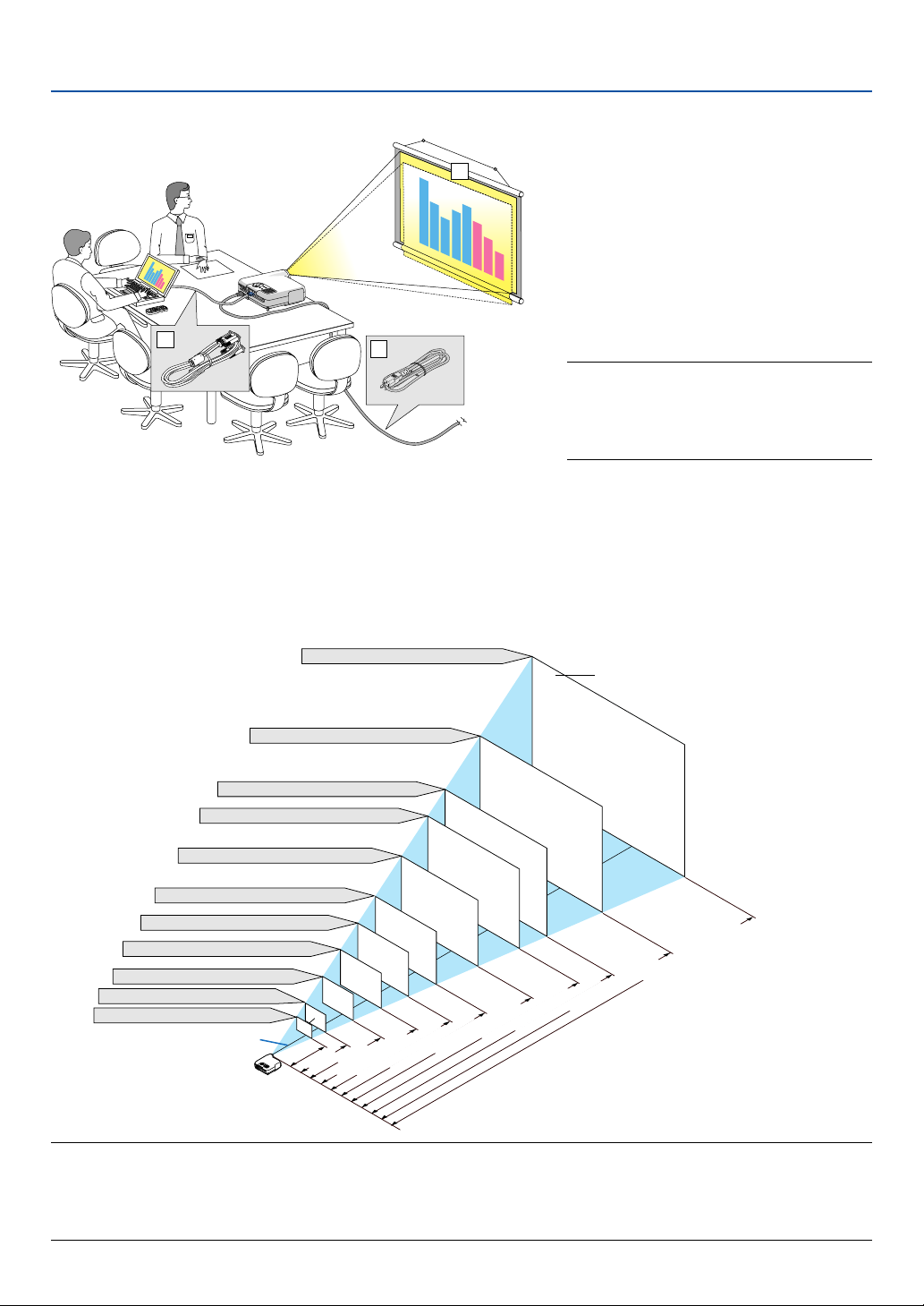
Portable Projector
LT265/LT245
User’s Manual
Important Information
Safety Cautions
Precautions
Please read this manual carefully before using your NEC LT265/LT245 Projector and keep the manual handy for future
reference. Your serial number is located on the bottom of your projector. Record it here:
CAUTION
To turn off main power, be sure to remove the plug from power outlet.
The power outlet socket should be installed as near to the equipment as possible, and should be easily
accessible.
CAUTION
TO PREVENT SHOCK, DO NOT OPEN THE CABINET.
NO USER-SERVICEABLE PARTS INSIDE.
REFER SERVICING TO QUALIFIED NEC SERVICE PERSONNEL.
This symbol warns the user that uninsulated voltage within the unit may be sufficient to cause electrical
shock. Therefore, it is dangerous to make any kind of contact with any part inside of the unit.
This symbol alerts the user that important information concerning the operation and maintenance of this
unit has been provided.
The information should be read carefully to avoid problems.
WARNING: TO PREVENT FIRE OR SHOCK, DO NOT EXPOSE THIS UNIT TO RAIN OR MOISTURE.
DO NOT USE THIS UNIT’S PLUG WITH AN EXTENSION CORD OR IN AN OUTLET UNLESS ALL THE PRONGS
CAN BE FULLY INSERTED.
DO NOT OPEN THE CABINET. THERE ARE HIGH-VOLTAGE COMPONENTS INSIDE. ALL SERVICING MUST
BE DONE BY QUALIFIED NEC SERVICE PERSONNEL.
DOC Compliance Notice (for Canada only)
This Class B digital apparatus meets all requirements of the Canadian Interference-Causing Equipment Regulations.
Acoustic Noise Information Ordinance-3. GSGV (for Germany only):
The sound pressure level is less than 70 dB (A) according to ISO 3744 or ISO 7779.
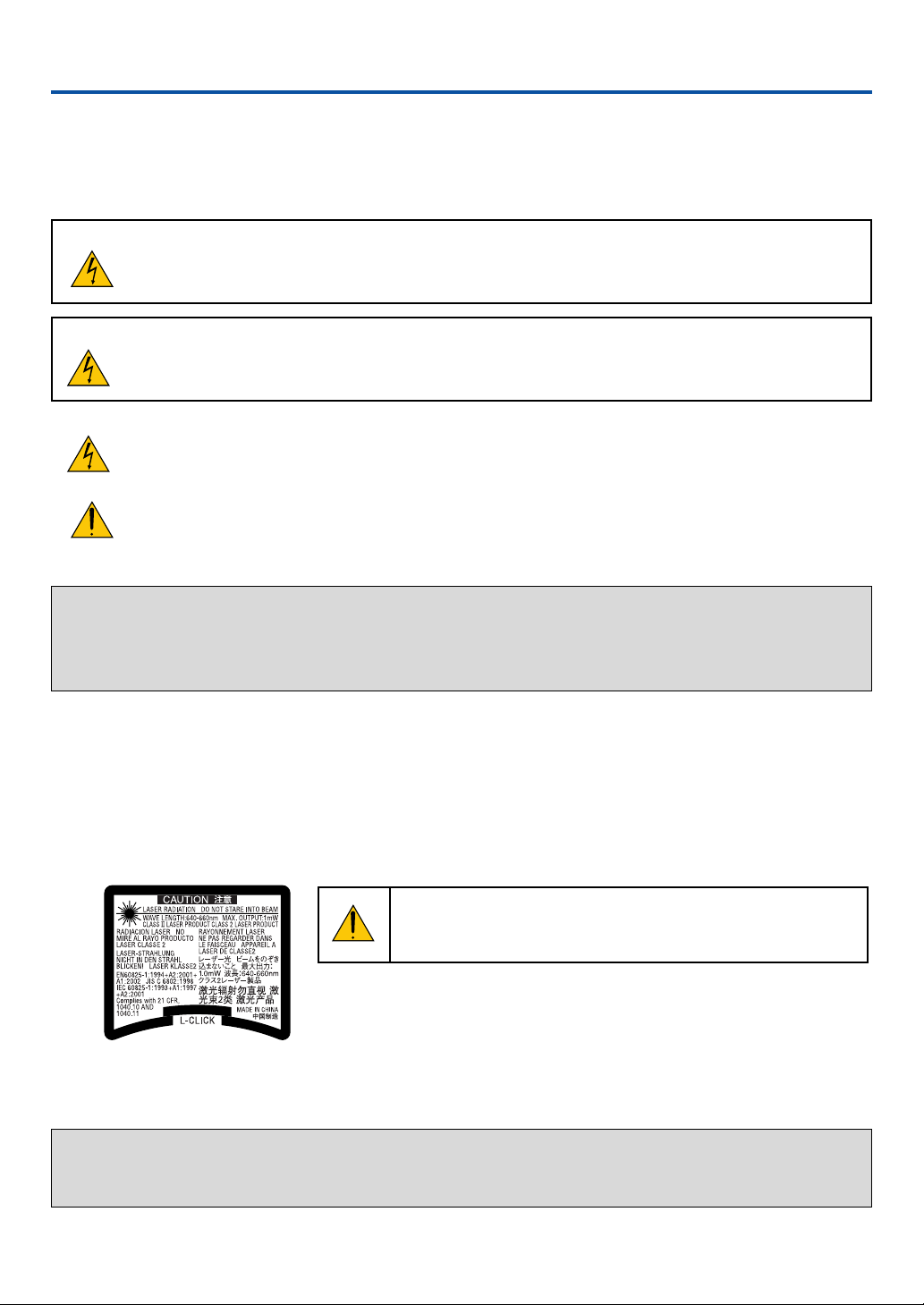
CAUTION
Do not look into the laser pointer while it is on and do not point the
laser beam at a person. Serious injury could result.
This label is underneath the remote control.
WARNING TO CALIFORNIA RESIDENTS:
Handling the cables supplied with this product, will expose you to lead, a chemical known to the State of California
to cause birth defects or other reproductive harm. Wash hands after handling.
Copyright © NEC Viewtechnology, Ltd. 2004
i

Important Information
RF Interference (for USA only)
WARNING
The Federal Communications Commission does not allow any modifications or changes to the unit EXCEPT those
specified by NEC Solutions (America), Inc. in this manual. Failure to comply with this government regulation could
void your right to operate this equipment. This equipment has been tested and found to comply with the limits for a
Class B digital device, pursuant to Part 15 of the FCC Rules. These limits are designed to provide reasonable
protection against harmful interference in a residential installation. This equipment generates, uses, and can radiate radio frequency energy and, if not installed and used in accordance with the instructions, may cause harmful
interference to radio communications. However, there is no guarantee that interference will not occur in a particular
installation.
If this equipment does cause harmful interference to radio or television reception, which can be determined by
turning the equipment off and on, the user is encouraged to try to correct the interference by one or more of the
following measures:
• Reorient or relocate the receiving antenna.
• Increase the separation between the equipment and receiver.
• Connect the equipment into an outlet on a circuit different from that to which the receiver is connected.
• Consult the dealer or an experienced radio / TV technician for help.
For UK only: In UK, a BS approved power cable with moulded plug has a Black (five Amps) fuse installed for use with
this equipment. If a power cable is not supplied with this equipment please contact your supplier.
Important Safeguards
These safety instructions are to ensure the long life of your projector and to prevent fire and shock. Please read them
carefully and heed all warnings.
Installation
1. For best results, use your projector in a darkened room.
2. Place the projector on a flat, level surface in a dry area away from dust and moisture.
3. Do not place your projector in direct sunlight, near heaters or heat radiating appliances.
Exposure to direct sunlight, smoke or steam can harm internal components.
4. To avoid premature lamp failure, do not tilt the front of the projector up or down by more than 7° from level.
5. Handle your projector carefully. Dropping or jarring can damage internal components.
6. Do not place heavy objects on top of the projector.
7. If you wish to have the projector installed on the ceiling:
a. Do not attempt to install the projector yourself.
b. The projector must be installed by qualified technicians in order to ensure proper operation and reduce the
risk of bodily injury.
c. In addition, the ceiling must be strong enough to support the projector and the installation must be in accor-
dance with any local building codes.
d. Please consult your dealer for more information.
ii

Important Information
Fire and Shock Precautions
1. Ensure that there is sufficient ventilation and that vents are unobstructed to prevent the build-up of heat inside
your projector. Allow at least 4 inches (10 cm) of space between your projector and a wall.
2. Prevent foreign objects such as paper clips and bits of paper from falling into your projector.
Do not attempt to retrieve any objects that might fall into your projector. Do not insert any metal objects such as
a wire or screwdriver into your projector. If something should fall into your projector, disconnect it immediately
and have the object removed by a qualified NEC service personnel.
3. Do not place any liquids on top of your projector.
4. Do not look into the lens while the projector is on. Serious damage to your eyes could result.
5. Keep any items such as magnifying glass out of the light path of the projector. The light being projected from the
lens is extensive, therefore any kind of abnormal objects that can redirect light coming out of the lens, can
cause unpredictable outcome such as fire or injury to the eyes.
6. Do not cover the lens with the supplied lens cap or equivalent while the projector is on. Doing so can lead to
melting of the cap and possibly burning your hands due to the heat emitted from the light output.
7. The projector is designed to operate on a power supply of 100-240V AC 50/60 Hz. Ensure that your power
supply fits this requirement before attempting to use your projector.
8. Handle the power cable carefully and avoid excessive bending.
A damaged cord can cause electric shock or fire.
9. If the projector is not to be used for an extended period of time, disconnect the plug from the power outlet.
10. Do not touch the power plug during a thunderstorm. Doing so can cause electrical shock or fire.
11. Do not handle the power plug with wet hands.
12. When using a LAN cable:
For safety, do not connect to the connector for peripheral device wiring that might have excessive voltage.
CAUTION
• Do not try to touch the ventilation outlet on the front side as it can become heated while the projector is turned
on.
• Do not use the tilt-foot for purposes other than originally intended. Misuses such as gripping the tilt-foot or
hanging on the wall can cause damage to the projector.
• Before putting the projector in the soft carrying case, be sure to retract the feet. Failure to do so may cause the
damage to the projector.
• Do not send the projector in the soft carrying case by parcel delivery service or cargo shipment. The projector
inside the soft carrying case could be damaged.
• Select [High] in Fan mode if you continue to use the projector for consecutive days. (From the menu, select
[Setup] → [Options] → [Fan Mode] → [High].)
• Do not unplug the power cable from the wall outlet under any one of the following circumstances.
Doing so can cause damage to the projector:
* While the projector's lamp lights.
* While the cooling fans are running. (The cooling fans continue to work for 90 seconds after the projector is
turned off).
* While the PC CARD Access Indicator lights. Doing so can damage your PC memory card.
iii

Important Information
Lamp Replacement
•To replace the lamp, follow all instructions provided on page 119.
• Be sure to replace the lamp when the message “The lamp has reached the end of its usable life. Please
replace the lamp.” appears. If you continue to use the lamp after the lamp has reached the end of its usable
life, the lamp bulb may shatter, and pieces of glass may be scattered in the lamp case. Do not touch them as the
pieces of glass may cause injury.
If this happens, contact your NEC dealer for lamp replacement.
• Allow a minimum of 90 seconds to elapse after turning off the projector. Then turn off the main power switch,
disconnect the power cable and allow 60 minutes to cool the projector before replacing the lamp.
iv

Table of Contents
Important Information ......................................................................... i
1. Introduction ......................................................................................1
What's in the Box? ........................................................................................................ 2
Introduction to the Projector ......................................................................................... 3
Part Names of the Projector ......................................................................................... 5
Carrying the Projector ............................................................................................. 5
Top Features ........................................................................................................... 7
Te r minal Panel Features ......................................................................................... 8
Part Names of the Remote Control ............................................................................ 10
2. Installation and Connections .................................................... 13
Setting Up the Screen and the Projector .................................................................... 14
Selecting a Location.............................................................................................. 14
Throw Distance and Screen Size.......................................................................... 15
Making Connections ................................................................................................... 17
Enabling the computer’s external display.............................................................. 17
Connecting Your PC or Macintosh Computer ........................................................ 17
To connect SCART output (RGB) ......................................................................... 18
Connecting an External Monitor ........................................................................... 19
Connecting Your DVD Player with Component Output .......................................... 20
Connecting Your VCR or Laser Disc Player .......................................................... 21
Connecting to a Network....................................................................................... 22
Inserting and Removing a PC Card ...................................................................... 24
Connecting the Supplied Power Cable ................................................................. 26
3. Projecting an Image (Basic Operation) ................................. 27
Tur ning on the Projector ............................................................................................. 28
Selecting a Source ..................................................................................................... 30
Adjusting the Picture Size and Position ...................................................................... 31
Correcting Keystone Distortion ................................................................................... 33
Optimizing an RGB Image Automatically ................................................................... 35
Tur ning Up or Down Volume ....................................................................................... 35
Using the Laser Pointer .............................................................................................. 36
쐊 Tur ning off the Projector ............................................................................................. 37
쐎 After Use..................................................................................................................... 37
4. Convenient Features.................................................................... 38
Tur ning Off the Image and Sound............................................................................... 39
Freezing a Picture....................................................................................................... 39
Using the Pointer ........................................................................................................ 39
Enlarging and Moving a Picture.................................................................................. 40
Getting Integrated Help .............................................................................................. 40
Using a USB Mouse ................................................................................................... 41
Using Remote Mouse Receiver .................................................................................. 42
v

Table of Contents
Correcting Horizontal and Vertical Keystone Distortion (Cornerstone) ....................... 43
쐎 Making Freehand Drawings on a Projected Image (ChalkBoard) .............................. 46
쐅
Storing Images Displayed on the Projector on the PC card or USB Memory (Capture)
쐈 Preventing Unauthorized Use of the Projector ........................................................... 48
쐉 Using a USB Memory Device or USB Memory Card Reader ..................................... 53
씈 Operation Using an HTTP Browser ............................................................................ 54
씉 Using the Projector to Operate a Computer Connected on a Network
(Desktop Control Utility 1.0) .................................................................................. 57
.......... 47
5. Using the Viewer ........................................................................... 62
Making the Most out of the Viewer Function............................................................... 63
Operating the Viewer Function from the Projector (playback) .................................... 64
쐋 Changing Background Logo ....................................................................................... 70
6. Using On-Screen Menu ................................................................ 71
Using the Menus......................................................................................................... 72
Menu tree ................................................................................................................... 73
Menu Elements........................................................................................................... 75
Menu Descriptions & Functions [Source] ................................................................... 76
쐄 Menu Descriptions & Functions [Adjust] ..................................................................... 79
쐂 Menu Descriptions & Functions [Setup] ..................................................................... 90
쐆 Menu Descriptions & Functions [Information] ........................................................... 112
쐊 Menu Descriptions & Functions [Reset] ................................................................... 116
7. Maintenance ................................................................................. 117
Cleaning the Cabinet ................................................................................................ 118
쐇 Cleaning the Lens..................................................................................................... 118
쐋 Replacing the Lamp.................................................................................................. 119
8. Appendix ........................................................................................ 122
Troubleshooting ........................................................................................................ 123
Specifications ........................................................................................................... 126
Cabinet Dimensions ................................................................................................. 128
Pin Assignments of D-Sub COMPUTER 1/2 Input Connector ................................. 129
Compatible Input Signal List ..................................................................................... 130
PC Control Codes and Cable Connection ................................................................ 131
Using Software Keyboard ......................................................................................... 132
Troubleshooting Check List ....................................................................................... 133
쐎 TravelCare Guide ...................................................................................................... 135
vi

1
Introduction
○○○○○○○○○○○○○○○○○○○○○○○○○○○○○○○○○○○○○○○○
What's in the Box? ....................................................... 2
Introduction to the Projector ........................................ 3
Part Names of the Projector ........................................ 5
Carrying the Projector ............................................................................................ 5
Top Features ........................................................................................................... 7
Te r minal Panel Features ......................................................................................... 8
Part Names of the Remote Control ........................... 10
Battery Installation ................................................................................................ 12
Operating Range for Wireless Remote Control .................................................... 12
Remote Control Precautions ................................................................................ 12
1
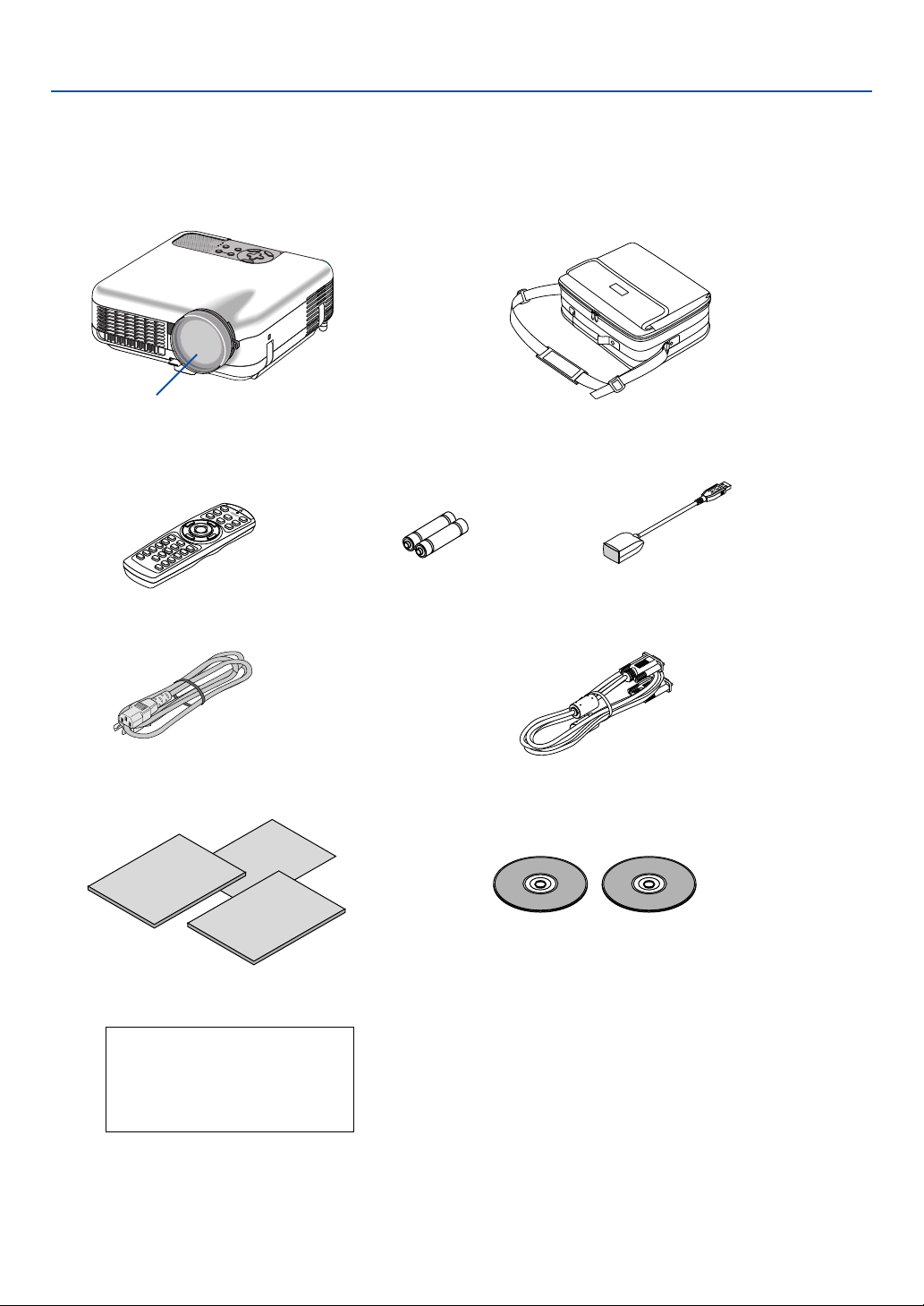
What's in the Box?
Make sure your box contains everything listed. If any pieces are missing, contact your dealer.
Please save the original box and packing materials if you ever need to ship your Projector.
1. Introduction
Lens cap
(24FT9351)
Important
Information
Remote control
(7N900491)
Power cable
(7N080204) US
(7N080003) EU
Quick
Connect
Guide
Projector
Soft carrying case
(24BS7114)
Batteries (AAA ⳯ 2) Remote mouse receiver
(7N900561)
RGB/VGA signal cable
(7N520032)
Software Utility
Installation Guide
For North America only
Registration card
Limited warranty
For Europe only
Guarantee policy
NEC
CD-ROM
User’s manual and User Supportware 2
• Security sticker
2

1. Introduction
Introduction to the Projector
This section introduces you to the LT265/LT245 Projector and describes key features and controls.
Congratulations on Your Purchase of the LT265/LT245 Projector
The LT265/LT245 is a sophisticated XGA projector that produces an enhanced display. With the LT265/LT245 you will
be able to project images up to 500” (measured diagonally). Enjoy crisp and sharp large screen display from your PC,
workstation or Macintosh computer, DVD player, VCR, satellite hookup, HDTV source, ) and images from your digital
camera PC Card, compact flash memory or USB storage device. The LT265/LT245 provides for enhanced security
options to help deter projector theft and provides for full projector control through the PC control port (mini DIN 8Pin)
and LAN support. With input and output flexibility, long lamp life and a full function remote, the LT265/LT245 lets you
enjoy larger than life viewing from a compact and easy to setup and use projector.
Features you’ll enjoy on the LT265/LT245:
•Automatic vertical keystone correction for fast and easy application setup.
• 3D Reform™ enhanced image technology for increased projector placement versatility that provides for
horizontal, vertical and diagonal keystone correction.
• Built-in Wall Color Correction presets provide for adaptive color correction when projecting onto non-white
screen material (or a wall).
• USB memory or PC card interfaces provide for computer-free presentations.
• Enhanced smart security settings for password protection, cabinet control panel lock, menu lock and PC card
protection key to help prevent unauthorized access, adjustments and theft deterrence.
• High resolution display - up to UXGA compatible, XGA native resolution.
•Variable audio out control of external amplified speakers via the projector remote.
• Extensive user adjustable picture and color management settings.
• Display 16:9 or 4:3 aspect ratio sources and fill the screen.
• HDTV (1080i, 720p) and SDTV (480p/576p, 480i/576i) compatibility.
• Digital photo viewer to display larger than life images from your digital cameras PC card, compact flash card or
USB storage device.
• Integrated RJ-45 connector for wired networking capability.
• Wireless networking capable.
Present from anywhere in the room when using as a wireless LAN projector, no physical signal cable connec-
tion to a PC is required.
* The NEC optional wireless LAN card is required (NWL-100* See page 99.).
• Supplied User Supportware 2 CD-ROM containing five software utilities allowing you to make the most of your
NEC projector.
• The supplied wireless remote control and remote mouse receiver allows you to operate your PC mouse wireless
from across the room. The remote mouse receiver supports most PCs with USB interface.
• Easy set up, use and operation.
• Eco-mode lamp technology for increased lamp life, reduced energy consumption and overall total cost of
ownership savings.
• Built-in laser pointer on the supplied remote control allows you to draw your audience's attention in a presentation.
3

1. Introduction
•Free downloadable Software Geometric Correction Tool 2.0.
Corrects the geometry of an image projected onto a cylindrical, spherical or corner screen via serial connection.
For additional information visit:
US : http://www.necvisualsystems.com
Europe : http://www.neceurope.com/
Global : http://www.nec-pj.com/
About this user's manual
The fastest way to get started is to take your time and do everything right the first time. Take a few minutes now to
review the user's manual. This may save you time later on. At the beginning of each section of the manual you'll find an
overview. If the section doesn't apply, you can skip it.
• IBM is a trademark or registered trademark of International Business Machines Corporation.
• Mac, Macintosh and PowerBook are trademarks of Apple Computer, Inc., registered in the U.S. and other
countries.
• Windows, Windows 98, Windows Me, Windows XP or Windows 2000 are trademarks or registered trademarks
of Microsoft Corporation.
• Digital Light Processing, DLP, Digital Micromirror Device and DMD are trademarks of Texas Instruments.
• Ulead is a trademark and/or registered trademark of Ulead Systems, Inc.
• Other product and company names mentioned in this user’s manual may be the trademarks or registered
trademarks of their respective holders.
4
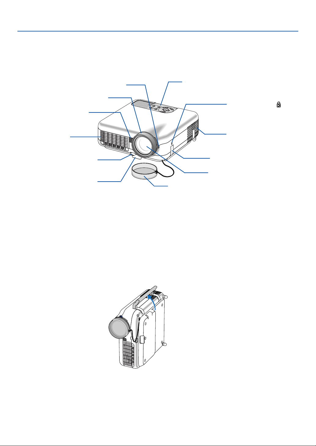
Part Names of the Projector
1. Introduction
Zoom Lever
(See page 32)
Focus Ring
(See page 32)
Remote Sensor
(See page 12)
Ventilation (outlet)
Heated air is exhausted
from here.
Adjustable Tilt Foot Lever
(See page 31)
Adjustable Tilt Foot
(See page 31)
Controls
(See page 7)
Built-in Security Slot ( )*
Ventilation (inlet)
Carrying Handle
Lens
Lens Cap
* This security slot supports the MicroSaver® Security System. MicroSaver® is a registered trademark of
Kensington Microware Inc. The logo is trademarked and owned by Kensington Microware Inc.
Carrying the Projector
Always carry your projector by the handle.
Ensure that the power cable and any other cables connecting to video sources are disconnected before moving the
projector.
When moving the projector or when it is not in use, cover the lens with the lens cap.
5
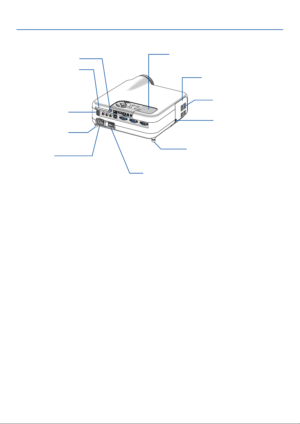
1. Introduction
PC Card Eject Button
PC Card Slot
Remote Sensor
(See page 12)
Rear Foot
AC Input
Connect the supplied power cable's
three-pin plug here, and plug the other
end into an active wall outlet.
(See page 26)
Monaural Speaker (2W)
Lamp cover
(See page 119)
Ventilation (outlet)
Lamp cover screw
Rear Foot
Rotate to make the projector level.
(See page 31)
Main Power Switch
When you plug the supplied power cable into an active wall
outlet and turn on the Main Power switch, the POWER
indicator turns orange and the projector is in standby mode.
(See page 28)
6
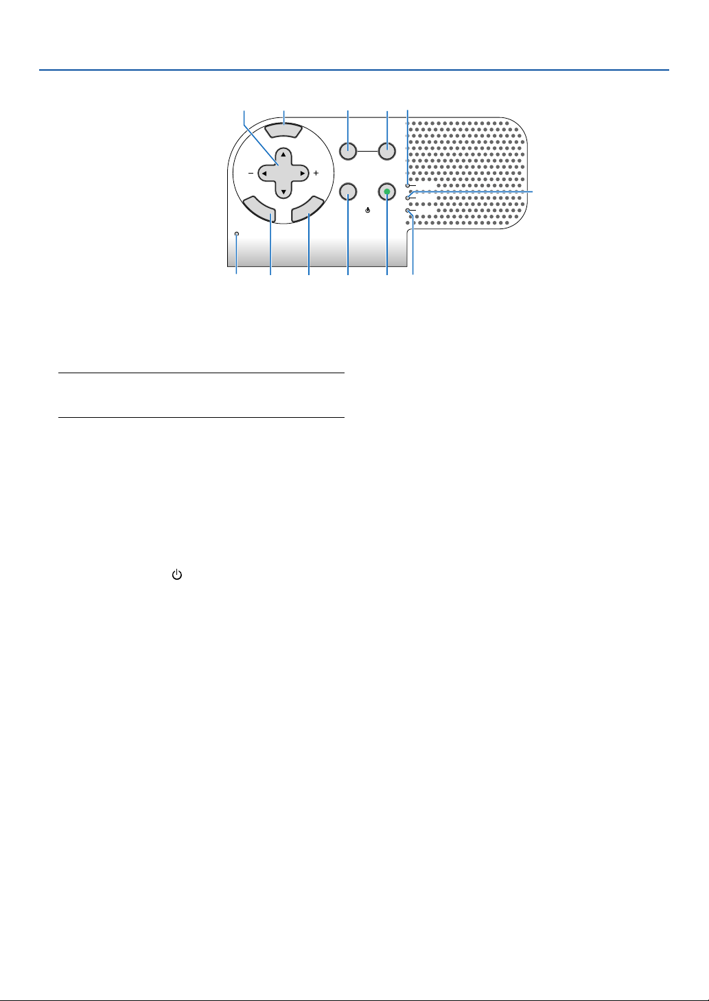
Top Features
PC CARD
SOURCE
AUTO ADJUST
3D REFORM
LAMP
STATUS
POWERON/STAND BY
E
N
T
E
R
E
X
I
T
M
E
N
U
SELECT
2
11
3
6
8
4
109
5
12 1
7
1. Introduction
1. POWER Button (ON / STAND BY)
Use this button to turn the power on and off when the
main power is supplied and the projector is in standby
mode.
NOTE: To turn on the projector, press and hold this button
for a minimum of two seconds. To turn off the projector,
press this button twice.
2. STATUS Indicator
If this light blinks red rapidly, it indicates that an error
has occurred, the lamp cover is not attached properly
or the projector has overheated. If this light remains
orange, it indicates that you have pressed a cabinet
key while the Cabinet Button Lock is enabled. See the
Status Indicator section on page 123 for more details.
3. POWER Indicator (
)
When this indicator is green, the projector is on; when
this indicator is orange, it is in standby mode. See the
Power Indicator section on page 123 for more details.
4. SOURCE Button
Use this button to select a video source such as a PC,
VCR, DVD player or Viewer (PC card).
Press and release this button quickly to display the
Source List.
6. PC CARD Access Indicator
Lights while accessing a PC card.
7. ENTER Button
Executes your menu selection and activates items
selected from the menu.
8. EXIT Button
Pressing this button will return to the previous menu
with saving changes.
While you are in the main menu, pressing this button
will close the menu.
9. SELECT 왖왔왗왘 (+) (–) / Volume Buttons
왖왔 : Use these buttons to select the menu of the
item you wish to adjust.
왗왘 : Use these buttons to change the level of a
selected menu item. When no menus appear,
these buttons work as a volume control.
When the pointer is displayed, these 왖왔왗왘 buttons
move the pointer.
10. MENU Button
Displays the menu.
Each time this button is pressed for a minimum of ONE
second, the input source will change as follows:
Computer1 → Computer2 → Video → S-Video →
Viewer → Computer1 → ...
If no input signal is present, the input will be skipped.
5. AUTO ADJUST Button
Use this button to adjust an RGB source for an optimal picture (See page 35).
11. LAMP Indicator
If this light blinks red rapidly, it's warning you that the
projection lamp has exceeded 2000 hours (up to 4000
hours in Eco mode) of service. After this light appears,
replace the lamp as soon as possible. (See page 119).
If this is lit green continually, it indicates that the lamp
mode is set to Eco. See the Lamp Indicator section
on page 123 for more details.
12. 3D REFORM Button
Press this button to enter 3D Reform mode to correct
the keystone (trapezoidal) distortion, and make the
image square.
7
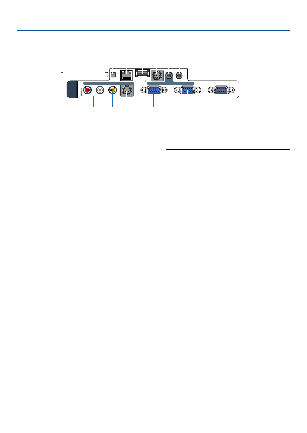
Te r minal Panel Features
13
PC CARD
R AUDIO IN L VIDEO IN
12
11 10
S-VIDEO IN
PC CONTROL
9
3 5
AUDIO OUT
USBLAN
COMPUTER 1 IN COMPUTER 2 IN
MONITOR OUTAUDIO IN
78 6 1 2 4
1. Introduction
1. COMPUTER 1 IN / Component Input Connector
(Mini D-Sub 15 Pin)
Connect your computer or other analog RGB equipment such as IBM compatible or Macintosh computers. Use the supplied RGB/VGA signal cable to connect to your computer. This also serves as a component input connector that allows you to connect a component video output of component equipment such
as a DVD player. This connector also supports SCART
output signal. See page 18 for more details.
2. COMPUTER 2 IN / Component Input Connector
(Mini D-Sub 15 Pin)
This connector has the same function as the COMPUTER 1 IN connector.
NOTE: The COMPUTER 2 IN does not support SCART
output signal and Plug & Play.
3. COMPUTER AUDIO IN Mini Jack (Stereo Mini)
This is where you connect audio output from your computer or DVD player. A commercially available audio
cable is required.
4. MONITOR OUT Connector (Mini D-Sub 15 Pin)
You can use this connector to loop your computer
image to an external monitor from the COMPUTER 1
or 2 input source.
The RGB analog signal set on “OUT Terminal” is output during Standby mode. See pages 19 and 109.
5. AUDIO OUT Mini Jack (Stereo Mini)
Connect an additional audio equipment here to listen
to audio coming from your computer, Video or S- Video
input.
• Output sound level can be adjusted in accordance
with the sound level of the internal speaker.
• When audio equipment is connected, the projec-
tor speaker is disabled.
• This jack cannot be used as a headphone jack.
6. S-VIDEO IN Connector (Mini DIN 4 Pin)
Here is where you connect the S-Video input from an
external source like a VCR.
NOTE: S-Video provides more vivid color and higher
resolution than the traditional composite video format.
7. VIDEO IN Connector (RCA)
Connect a VCR, DVD player, laser disc player, or document camera here to project video.
8. VIDEO AUDIO IN Jacks (RCA)
L: This is your left channel audio input for stereo
sound coming from the VIDEO source.
R: This is your right channel audio input for stereo
sound from the VIDEO source.
9. PC CONTROL Port (Mini DIN 8 Pin)
Use this port to connect your PC or control system to
control your projector via a serial cable. This enables
you to control the projector using serial communication protocol. The NEC optional serial cable (CA03D)
is required to use this port. You can also control the
projector by using PC Control Utility 3.0 contained on
the supplied User Supportware 2 CD-ROM.
To do so you must first have PC Control Utility 3.0
installed on your PC. If you are writing your own program, typical PC control codes are on page 131.
10. USB Port (Type A)
Connect a commercially available USB memory device or mouse that supports USB. You can operate
the menu or Viewer with the USB mouse via this port.
Note that this port should not be connected to a computer and that there may be some brands of USB
mouse that the projector does not support.
11. LAN Port (RJ-45)
This port is typically used for UTP Ethernet/Fast
Ethernet. Use this connector to control the projector
on a LAN. See page 22.
8

Te r minal Panel Features
12
11 10
S-VIDEO IN
PC CARD
13
R AUDIO IN L VIDEO IN
78 6 1 2 4
12. PC CARD Eject Button
Press to eject a PC card partially.
13. PC CARD Slot
Insert a PC memory card or NEC optional wireless
LAN card here.
9
3 5
USBLAN
COMPUTER 1 IN COMPUTER 2 IN
PC CONTROL
1. Introduction
AUDIO OUT
MONITOR OUTAUDIO IN
9
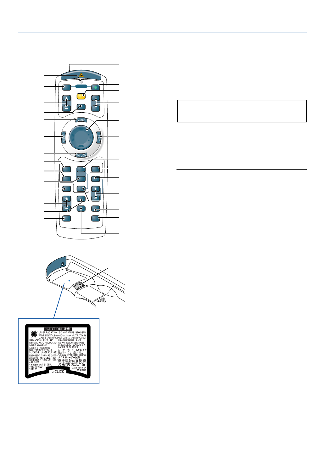
쐏 Part Names of the Remote Control
1. Introduction
9
11
13
15
16
18
21
22
24
23
1
2
4
OFF
MAGNIFY
5
POWER
LASER
POINTER
ON
PAGE
UP
DOWN
3
6
8
7
10
12
VIDEO
S-VIDEO
PIC-MUTE
VOLUME
FREEZE
COMPUTER
1
2
AUTO ADJ.
HELP
ASPECT
LAN
VIEWER
SLIDE
PICTURE
3D REFORM
17
20
26
27
19
28
1. Infrared Transmitter/Laser Pointer
Tr ansmits an infrared signal when any button other
than LASER is pressed.
Direct the remote control toward the remote sensor
on the projector cabinet.
Beams a laser light when the Laser button is pressed.
CAUTION:
* Do not look into the laser pointer while it is on.
* Do not point the laser beam at a person.
2. LED
Flashes when any button is pressed.
3. POWER ON Button
When the main power is on, you can use this button
to turn your projector on.
NOTE: To turn on the projector, press and hold the
POWER ON button for a minimum of two seconds.
4. POWER OFF Button
You can use this button to turn your projector off.
NOTE: To turn off the projector, press the POWER
OFF button twice.
29
5. MAGNIFY (+)(–) Buttons
25
Use these buttons to adjust the image size.
The image can be magnified about the center of the
screen up to 400%. See page 40.
14
6. LASER Button
Press and hold this button to activate the laser pointer.
When lit, you can use the laser to draw your audience's
attention to a red dot that you can place on any object.
7. POINTER Button
Press this button to display the projector pointer. You
can move your pointer icon to the area you want on
the screen using the Select button. See page 39.
8. PAGE UP/DOWN Buttons
Use these buttons to operate your computer with the
supplied remote mouse receiver. You can use these
buttons to scroll the viewing area of the window or to
move to the previous or next slide in PowerPoint on
your computer.
9. MENU Button
Displays the menu for various settings and adjustments.
10

1. Introduction
10. Select Button
This button is used for projector’s menu operation and
moving the magnified image.
This button also works as a computer mouse when
the supplied remote mouse receiver is connected with
your computer. See page 42.
11. ENTER Button
Executes your menu selection and activates items
selected from the menu.
12. EXIT Button
Returns to the previous menu.
While you are in the main menu, pressing this button
will close the menu.
13. R-CLICK Button
Works as the mouse right button when the supplied
remote mouse receiver is connected with your computer.
14. L-CLICK Button
Works as the mouse left button when the supplied
remote mouse receiver is connected with your computer.
15. VIDEO Button
Press this button to select a video source from a VCR,
DVD player, laser disc player or document camera.
23. FREEZE Button
This button will freeze a picture. Press again to resume motion. See page 39.
24. HELP Button
Provides the Information screen. See page 40.
25. ASPECT Button
Press this button to display the Aspect Ratio select
menu. See page 81.
26. VIEWER Button
Press this button to select the Viewer source. See page
64.
27. SLIDE +/- Buttons
Press (+) to select the next folder or slide and press
(–) to select the previous folder or slide.
28. PICTURE Button
Press to display the picture adjustment screen. Pressing this button sequentially selects "Brightness" →
"Contrast" → "Color" → "Hue" → "Sharpness" → "Wall
Color". See pages 79 and 80.
29. 3D REFORM Button
Press this button to enter 3D Reform to correct the
keystone (trapezoidal) distortion, and make the image square. See pages 33 and 43.
16. S-VIDEO Button
Press this button to select an S-Video source from a
VCR.
17. COMPUTER 1 Button
Press this button to select COMPUTER 1 input.
18. COMPUTER 2 Button
Press this button to select COMPUTER 2 input.
19. AUTO ADJ. Button
Use this button to adjust an RGB source (COMPUTER
1 or 2) for an optimal picture. See page 35.
20. LAN Button
Press this button to select the LAN (Local Area Network) connection.
21. PIC-MUTE Button
This button turns off the image and sound for a short
period of time. Press again to restore the image and
sound. See page 39.
22. VOLUME +/– Buttons
Press (+) to increase the volume and (–) to decrease
it. See page 35.
11
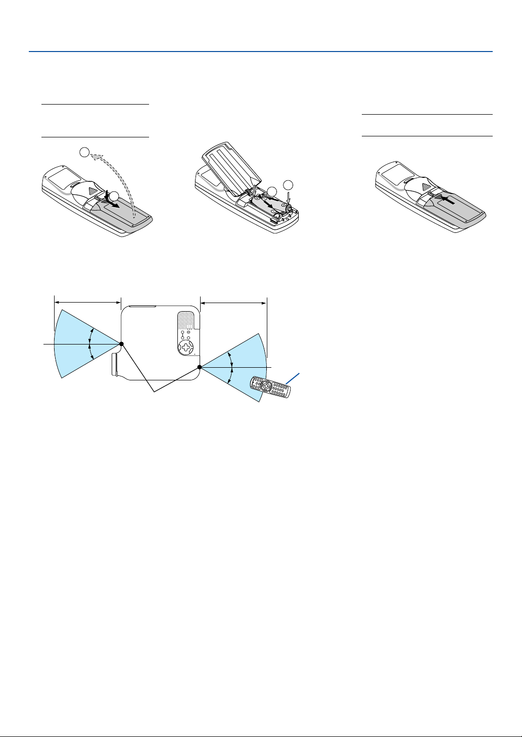
Battery Installation
1. Introduction
1
Remove the battery cover.
NOTE: Do not pull the battery
cover by force. Doing so can
result in it coming off.
2
1
2
Remove both old batteries and
install new ones (AAA). Ensure
that you have the batteries' polarity (+/ –) aligned correctly.
Operating Range for Wireless Remote Control
7m/22 feet
30°
30°
7m/22 feet
30°
30°
3
Slip the cover back over the batteries until it snaps into place.
NOTE: Do not mix different types of
batteries or new and old batteries.
2
1
Remote control
Remote sensor on projector cabinet
• The infrared signal operates by line-of-sight up to a distance of about 22 feet/7 m and within a 60-degree angle of
the remote sensor on the projector cabinet.
• The projector will not respond if there are objects between the remote control and the sensor, or if strong light falls
on the sensor.
Weak batteries will also prevent the remote control from properly operating the projector.
Remote Control Precautions
• Handle the remote control carefully.
• If the remote control gets wet, wipe it dry immediately.
•Avoid excessive heat and humidity.
• If you will not be using the remote control for a long time, remove the batteries.
• Do not place the batteries upside down.
• Do not use new and old batteries together, or use different types of batteries together.
• Dispose of used batteries according to your local regulations.
12

2
Installation and Connections
○○○○○○○○○○○○○○○○○○○○○○○○○○○○○○○○○○○○○○○○
Setting Up the Screen and the Projector ................... 14
Selecting a Location ............................................................................................. 14
Throw Distance and Screen Size ......................................................................... 15
Making Connections .................................................. 17
Enabling the computer’s external display ............................................................. 17
Connecting Your PC or Macintosh Computer ....................................................... 17
To connect SCART output (RGB)......................................................................... 18
Connecting an External Monitor ........................................................................... 19
Connecting Your DVD Player with Component Output ......................................... 20
Connecting Your VCR or Laser Disc Player .......................................................... 21
Connecting to a Network ...................................................................................... 22
Inserting and Removing a PC Card ...................................................................... 24
Connecting the Supplied Power Cable ................................................................. 26
13
2. Installation and Connections
This section describes how to set up your projector and how to connect PCs, video and audio sources.
1
But before you get started, you must first:
z Set up a screen and the projector.
x Connect your computer or video equip-
ment to the projector. See pages 17 -
25.
c Connect the supplied power cable. See
Your projector is simple to set up and use.
2
3
page 26.
NOTE: Ensure that the power cable and any
other cables are disconnected before moving
the projector. When moving the projector or
when it is not in use, cover the lens with the
To the wall outlet.
lens cap.
Setting Up the Screen and the Projector
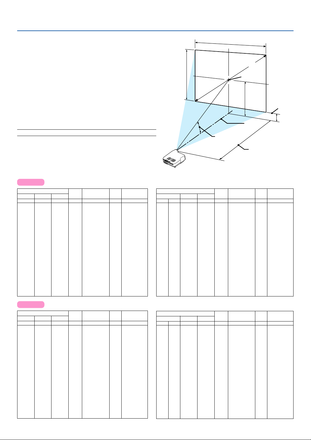
Selecting a Location
The further your projector is from the screen or wall, the larger the image. The minimum size the image can be is
approximately 30 inches (0.8 m) measured diagonally when the projector is roughly 51.2 inches (1.3 m) from the wall
or screen. The largest the image can be is 500 inches (12.7 m) when the projector is about 970 inches (24.6 m) from
the wall or screen. Use the drawing below as a guide.
609.6 (W) ⳯ 457.2 (H) / 240 (W) ⳯ 180 (H)
Screen size (Unit: cm/inch)
300"
Screen size
487.7 (W) ⳯ 365.8 (H) / 192 (W) ⳯ 144 (H)
240"
406.4 (W) ⳯ 304.8 (H) / 160 (W) ⳯ 120 (H)
365.8 (W) ⳯ 274.3 (H) / 144 (W) ⳯ 108 (H)
304.8 (W) ⳯ 228.6 (H) / 120 (W) ⳯ 90 (H)
243.8 (W) ⳯ 182.9 (H) / 96 (W) ⳯ 72 (H)
203.2 (W) ⳯ 152.4 (H) / 80 (W) ⳯ 60 (H)
162.6 (W) ⳯ 121.9 (H) / 64 (W) ⳯ 48 (H)
121.9 (W) ⳯ 91.4 (H) / 48 (W) ⳯ 36 (H)
81.3 (W) ⳯ 61.0 (H) / 32 (W) ⳯ 24 (H)
61.0 (W) ⳯ 45.7 (H) / 24 (W) ⳯ 18 (H)
Lens center
30"
1.3/50.8
(1.0/39.5)
40"
1.7/68.5
(1.4/53.3)
60"
120"
100"
80"
2.6/103.8
(2.1/80.9)
3.5/139.2 (2.8/108.6)
5.3/209.9 (4.2/163.8)
4.4/174.5 (3.5/136.2)
200"
180"
150"
6.7/262.9 (5.2/205.2)
8.9/351.3 (7.0/274.3)
8.0/315.9 (6.3/246.7)
Distance
13.4/528.0 (10.5/412.4)
10.7/422.0 (8.4/329.5)
Unit: m/inch
NOTE:
•Values in parentheses for LT245.
• The screen sizes above are intermediate values between tele (minimum display area) and wide (maximum display area). Image
size can be adjusted with the zoom adjustment up to a maximum of 10%.
•To avoid premature lamp failure, do not tilt the front of the projector up or down by more than 7° from level.
14
2. Installation and Connections
Throw Distance and Screen Size
The following shows the proper relative positions of the projector and screen. Refer to the table to determine the position of installation.
Distance Chart
B = Vertical distance between lens center and screen cen-
ter
C = Throw distance
D = Vertical distance between lens center and bottom of
screen (top of screen for ceiling application)
α = Throw angle
NOTE: Distances may vary +/-5%.
LT265
Screen Size B C
Diagonal Width Height
inch
100
120
150
180
200
210
240
261
270
300
350
400
450
500
inch
120
144
160
168
192
209
216
240
280
320
360
400
inch
24
18
32
24
48
36
54
40
58
43
64
48
50
67
72
54
80
60
72
96
90
108
120
126
144
157
162
180
210
240
270
300
30
40
60
67
72
80
84
90
inch
12.6
16.8
25.2
28.1
30.2
33.6
35.3
37.8
42.0
50.4
63.0
75.6
84.0
88.2
100.8
109.7
113.5
126.1
147.1
168.1
189.1
210.1
Wide – Tele
inch
45.6 – 56.0
61.5 – 75.4
93.5 – 114.1
104.7 – 127.7
112.7 – 137.4
125.5 – 152.9
131.9 – 160.6
141.5 – 172.2
157.4 – 191.6
189.4 – 230.3
237.3 – 288.4
285.3 – 346.6
317.2 – 385.3
333.2 – 404.7
381.2 – 462.8
414.7 – 503.4
429.1 – 520.9
477.0 – 579.0
557.0 – 675.8
636.9 – 772.7
716.8 – 869.5
796.7 – 966.4
inch
10.1
10.8
12.0
14.4
18.0
21.6
24.0
25.2
28.8
31.4
32.5
36.1
42.1
48.1
54.1
60.1
D
3.6
4.8
7.2
8.0
8.6
9.6
α
Wide – Tele
degree
15.4 – 12.7
15.3 – 12.6
15.1 – 12.5
15.0 – 12.4
15.0 – 12.4
15.0 – 12.4
15.0 – 12.4
15.0 – 12.4
14.9 – 12.4
14.9 – 12.3
14.9 – 12.3
14.8 – 12.3
14.8 – 12.3
14.8 – 12.3
14.8 – 12.3
14.8 – 12.3
14.8 – 12.3
14.8 – 12.3
14.8 – 12.3
14.8 – 12.3
14.8 – 12.3
14.8 – 12.3
Screen Height
Screen Size B C
Diagonal Width Height
mm
inch
762
30
1016
40
1524
60
1702
67
1829
72
2032
80
2134
84
2286
90
2540
100
3048
120
3810
150
4572
180
5080
200
5334
210
6096
240
6629
261
6858
270
7620
300
8890
350
10160
400
11430
450
12700
500
10160
mm
610
813
1219
1361
1463
1626
1707
1829
2032
2438
3048
3658
4064
4267
4877
5304
5486
6096
7112
8128
9144
mm
1021
1097
1219
1280
1372
1524
1829
2286
2743
3048
3200
3658
3978
4115
4572
5334
6096
6858
7620
457
610
914
Screen Width
Throw Angle (움)
Wide – Tele
mm
1,157 – 1,423
320
1,563 – 1,915
427
2,375 – 2,899
640
2,659 – 3,243
714
2,862 – 3,489
768
3,187 – 3,883
853
3,349 – 4,080
896
3,593 – 4,375
960
3,999 – 4,867
1067
4,811 – 5,851
1280
6,028 – 7,327
1601
7,246 – 8,802
1921
8,058 – 9,786
2134
8,464 –10,278
2241
9,682 –11,754
2562
10,534 –12,787
2786
10,899 –13,230
2882
12,117 –14,706
3202
14,147 –17,166
3736
16,176 –19,626
4270
18,206 –22,086
4804
20,235 –24,545
5337
Screen Diagonal
Screen center
(B)
Lens Center
Throw Distance (C)
mm
mm
1069
1222
1375
1527
D
122
183
204
219
244
256
274
305
366
458
549
610
641
733
797
824
916
91
Screen Bottom
(D)
α
Wide – Tele
degree
15.4 – 12.7
15.3 – 12.6
15.1 – 12.5
15.0 – 12.4
15.0 – 12.4
15.0 – 12.4
15.0 – 12.4
15.0 – 12.4
14.9 – 12.4
14.9 – 12.3
14.9 – 12.3
14.8 – 12.3
14.8 – 12.3
14.8 – 12.3
14.8 – 12.3
14.8 – 12.3
14.8 – 12.3
14.8 – 12.3
14.8 – 12.3
14.8 – 12.3
14.8 – 12.3
14.8 – 12.3
LT245
Screen Size B C
Diagonal Width Height
inch
100
120
150
180
200
210
240
261
270
300
350
400
450
500
inch
inch
30
40
60
67
72
80
84
90
120
144
160
168
192
209
216
240
280
320
360
400
18
24
32
24
48
36
40
54
58
43
64
48
50
67
72
54
80
60
72
96
90
108
120
126
144
157
162
180
210
240
270
300
inch
12.5
16.7
25.1
28.1
30.2
33.5
35.2
37.7
41.9
50.3
62.9
75.5
83.9
88.1
100.7
109.5
113.3
125.9
146.9
167.9
188.9
209.9
Wide – Tele
inch
35.7 – 43.3
48.2 – 58.4
73.3 – 88.5
82.1 – 99.1
88.4 – 106.6
98.5 – 118.7
103.5 – 124.7
111.0 – 133.7
123.6 – 148.8
148.7 – 178.9
186.3 – 224.1
224.0 – 269.3
249.1 – 299.5
261.7 – 314.5
299.3 – 359.7
325.7 – 391.4
337.0 – 405.0
374.6 – 450.2
437.4 – 525.5
500.2 – 600.8
563.0 – 676.2
625.7 – 751.5
inch
10.0
10.7
11.9
14.3
17.9
21.5
23.9
25.1
28.7
31.2
32.3
35.9
41.9
47.9
53.9
59.9
D
3.5
4.7
7.1
8.0
8.6
9.5
α
Wide – Tele
degree
19.4 – 16.2
19.1 – 16.0
18.9 – 15.9
18.9 – 15.8
18.8 – 15.8
18.8 – 15.8
18.8 – 15.8
18.8 – 15.8
18.7 – 15.7
18.7 – 15.7
18.7 – 15.7
18.6 – 15.7
18.6 – 15.7
18.6 – 15.7
18.6 – 15.6
18.6 – 15.6
18.6 – 15.6
18.6 – 15.6
18.6 – 15.6
18.6 – 15.6
18.5 – 15.6
18.5 – 15.6
Screen Size B C
Diagonal Width Height
mm
inch
762
30
1016
40
1524
60
1702
67
1829
72
2032
80
2134
84
2286
90
2540
100
3048
120
3810
150
4572
180
5080
200
5334
210
6096
240
6629
261
6858
270
7620
300
8890
350
10160
400
11430
450
12700
500
10160
15
mm
610
813
1219
1361
1463
1626
1707
1829
2032
2438
3048
3658
4064
4267
4877
5304
5486
6096
7112
8128
9144
mm
457
610
914
1021
1097
1219
1280
1372
1524
1829
2286
2743
3048
3200
3658
3978
4115
4572
5334
6096
6858
7620
mm
319
425
639
713
766
852
894
958
1065
1278
1598
1918
2132
2238
2558
2782
2878
3198
3731
4264
4798
5331
Wide – Tele
mm
906 – 1,100
1,225 – 1,483
1,863 – 2,248
2,086 – 2,516
2,246 – 2,707
2,501 – 3,014
2,628 – 3,167
2,820 – 3,396
3,139 – 3,779
3,776 – 4,545
4,733 – 5,693
5,689 – 6,841
6,327 – 7,607
6,646 – 7,989
7,603 – 9,137
8,272 – 9,941
8,559 –10,286
9,516 –11,434
11,110 –13,348
12,705 –15,261
14,299 –17,175
15,893 –19,089
D
mm
120
181
203
218
242
254
273
303
364
455
547
608
638
729
793
821
912
1064
1216
1369
1521
90
α
Wide – Tele
degree
19.4 – 16.2
19.1 – 16.0
18.9 – 15.9
18.9 – 15.8
18.8 – 15.8
18.8 – 15.8
18.8 – 15.8
18.8 – 15.8
18.7 – 15.7
18.7 – 15.7
18.7 – 15.7
18.6 – 15.7
18.6 – 15.7
18.6 – 15.7
18.6 – 15.6
18.6 – 15.6
18.6 – 15.6
18.6 – 15.6
18.6 – 15.6
18.6 – 15.6
18.5 – 15.6
18.5 – 15.6

2. Installation and Connections
WARNING
* Installing your projector on the ceiling must be done
by a qualified technician. Contact your NEC dealer for
more information.
* Do not attempt to install the projector yourself.
• Only use your projector on a solid, level surface. If the
projector falls to the ground, you can be injured and
the projector severely damaged.
• Do not use the projector where temperatures vary
greatly. The projector must be used at temperatures
between 41˚F (5˚C) and 95˚F (35˚C).
• Do not expose the projector to moisture, dust, or
smoke. This will harm the screen image.
• Ensure that you have adequate ventilation around your
projector so heat can dissipate. Do not cover the vents
on the side or the front of the projector.
Reflecting the Image
Using a mirror to reflect your projector's image enables
you to enjoy a much larger image. Contact your NEC
dealer if you need a mirror system. If you're using a mirror system and your image is inverted, use the MENU
and SELECT buttons on your projector cabinet or your
remote control to correct the orientation. See page 98.
16
2. Installation and Connections
Making Connections
NOTE: When using with a notebook PC, be sure to connect between the projector and the notebook PC before turning on the
power to the notebook PC. In most cases signal cannot be output from RGB output unless the notebook PC is turned on after
connecting with the projector.
* If the screen goes blank while using your remote control, it may be the result of the computer's screen-saver or power
management software.
Enabling the computer’s external display
Displaying an image on the notebook PC’s screen does not necessarily mean it outputs a signal to the projector.
When using a PC compatible laptop, a combination of function keys will enable/disable the external display.
Usually, the combination of the ‘Fn” key along with one of the 12 function keys gets the external display to come on
or off. For example, NEC laptops use Fn + F3, while Dell laptops use Fn + F8 key combinations to toggle through
external display selections.
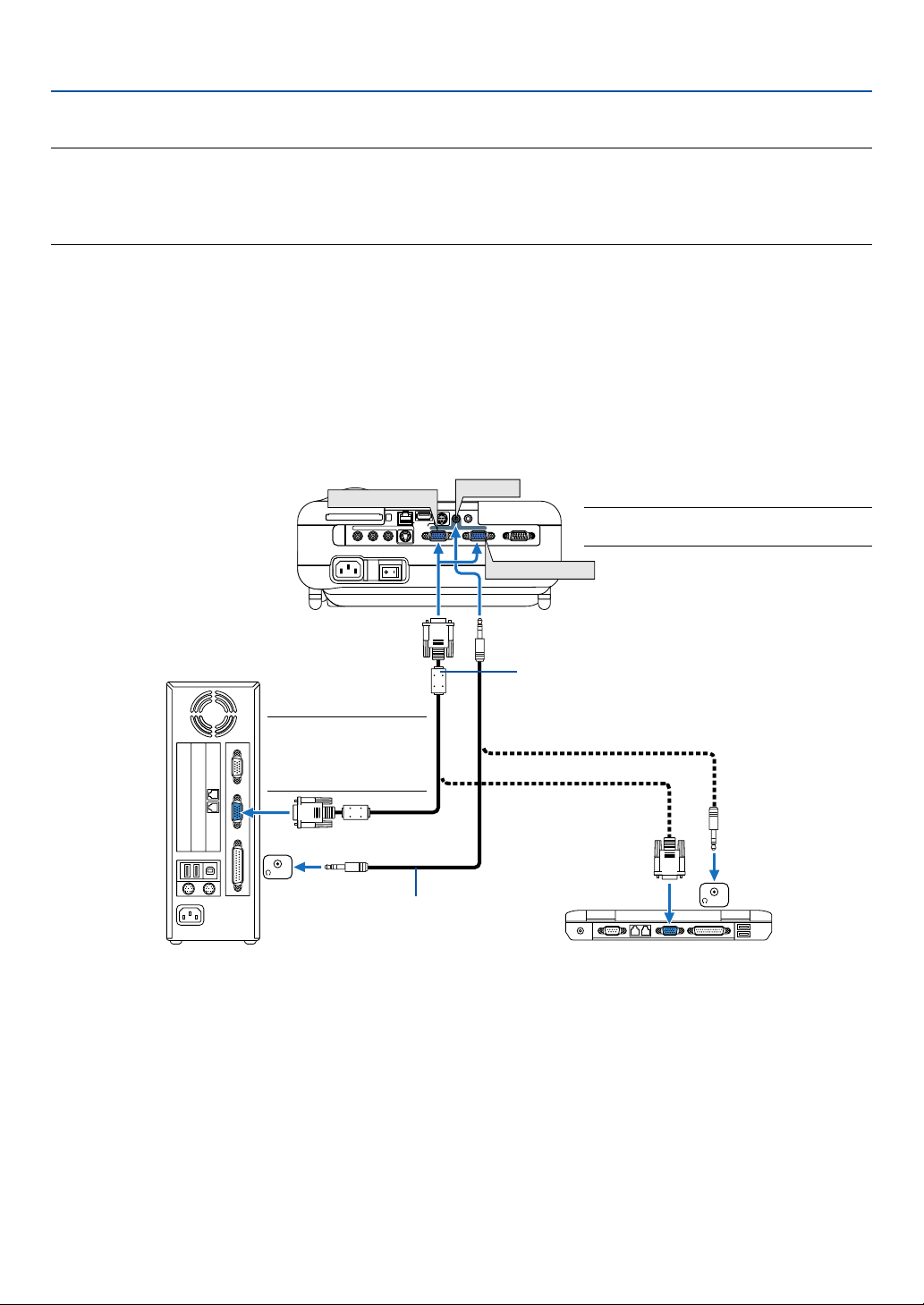
Connecting Your PC or Macintosh Computer
PC CARD
NOTE: For older Macintosh, use
a commercially available pin
adapter (not supplied) to
connect to your Mac's video
port.
PHONE
IBM PC or Compatibles (Desktop type)
or Macintosh (Desktop type)
USBLAN
PC CONTROL
COMPUTER 1 IN COMPUTER 2 IN
AUDIO IN
AUDIO OUT
COMPUTER 1 IN
R AUDIO IN L
VIDEO IN
S-VIDEO IN
AC IN
Audio cable (not supplied)
MONITOR OUTAUDIO IN
NOTE: The COMPUTER 1 IN connector
supports Plug & Play (DDC2).
COMPUTER 2 IN
RGB/VGA signal cable (supplied)
To mini D-Sub 15-pin connector on the projector. It is
recommended that you use a commercially available
distribution amplifier if connecting a signal cable longer
than the supplied one.
PHONE
IBM VGA or Compatibles (Notebook
type) or Macintosh (Notebook type)
Connecting your PC or Macintosh computer to your projector will enable you to project your computer's screen image
for an impressive presentation.
To connect to a PC or Macintosh, simply:
1. Turn off the power to your projector and computer.
2. Use the supplied RGB/VGA signal cable to connect your PC or Macintosh to the projector.
3. Connect the supplied power cable. See page 26.
4. Turn on the projector and the computer.
5. If the projector goes blank after a period of inactivity, it may be caused by a screen saver installed on the computer
you've connected to the projector.
17
2. Installation and Connections
NOTE: The LT265/LT245 is not compatible with video decoded outputs of either the NEC ISS-6020 and ISS-6010 switchers.
NOTE: An image may not be displayed correctly when a Video or S-Video source is played back via a commercially available scan
converter.
This is because the projector will process a video signal as a computer signal at the default setting. In that case, do the following.
* When an image is displayed with the lower and upper black portion of the screen or a dark image is not displayed correctly:
Project an image to fill the screen and then press the AUTO ADJ button on the remote control or the AUTO ADJUST button on
the projector cabinet.
* When noise appears on the sides of the screen:
Use the Overscan feature to display the image correctly.
Be sure to change the Overscan to 0% before pressing the AUTO ADJ or AUTO ADJUST button, otherwise an image may be
displayed with its sides cut off.
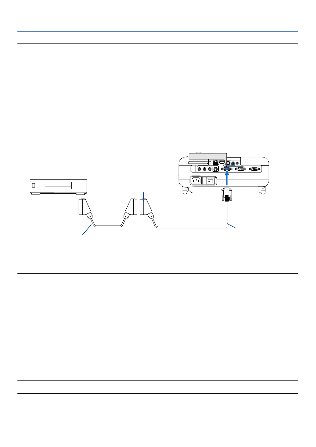
To connect SCART output (RGB)
Projector
MONITOR OUTAUDIO IN
Video equipment such as DVD player
Female
COMPUTER 1 IN
PC CARD
R AUDIO IN L
VIDEO IN
S-VIDEO IN
AC IN
USBLAN
PC CONTROL
COMPUTER 1 IN COMPUTER 2 IN
AUDIO OUT
ADP-SC1
Commercially available SCART cable
Before connections: An exclusive SCART adapter (ADP-SC1) and a commercially available SCART cable are required for this connection.
NOTE: Audio signal is not available for this connection.
1. Turn off the power to the projector and your video equipment.
2. Use the NEC ADP-SC1 SCART adapter and a commercially available SCART cable to connect the COMPUTER 1
IN connector of your projector and a SCART output (RGB) of your video equipment.
3. Connect the supplied power cable. See page 26.
4. Turn on the power to the projector and your video equipment.
5. Use the COMPUTER 1 button on the remote control to select the COMPUTER 1 IN connector.
6. Press the MENU button on the remote control to display the menu.
7. From the menu, select [Setup] → [Options] → [Signal Select] → [Computer 1] → [Scart].
SCART is a standard European audio-visual connector for TVs, VCRs and DVD players. It is also referred to as
Euro-connector.
NOTE: The ADP-SC1 SCART adapter is obtainable from your NEC dealer in Europe. Contact your NEC dealer in Europe for more
information.
18
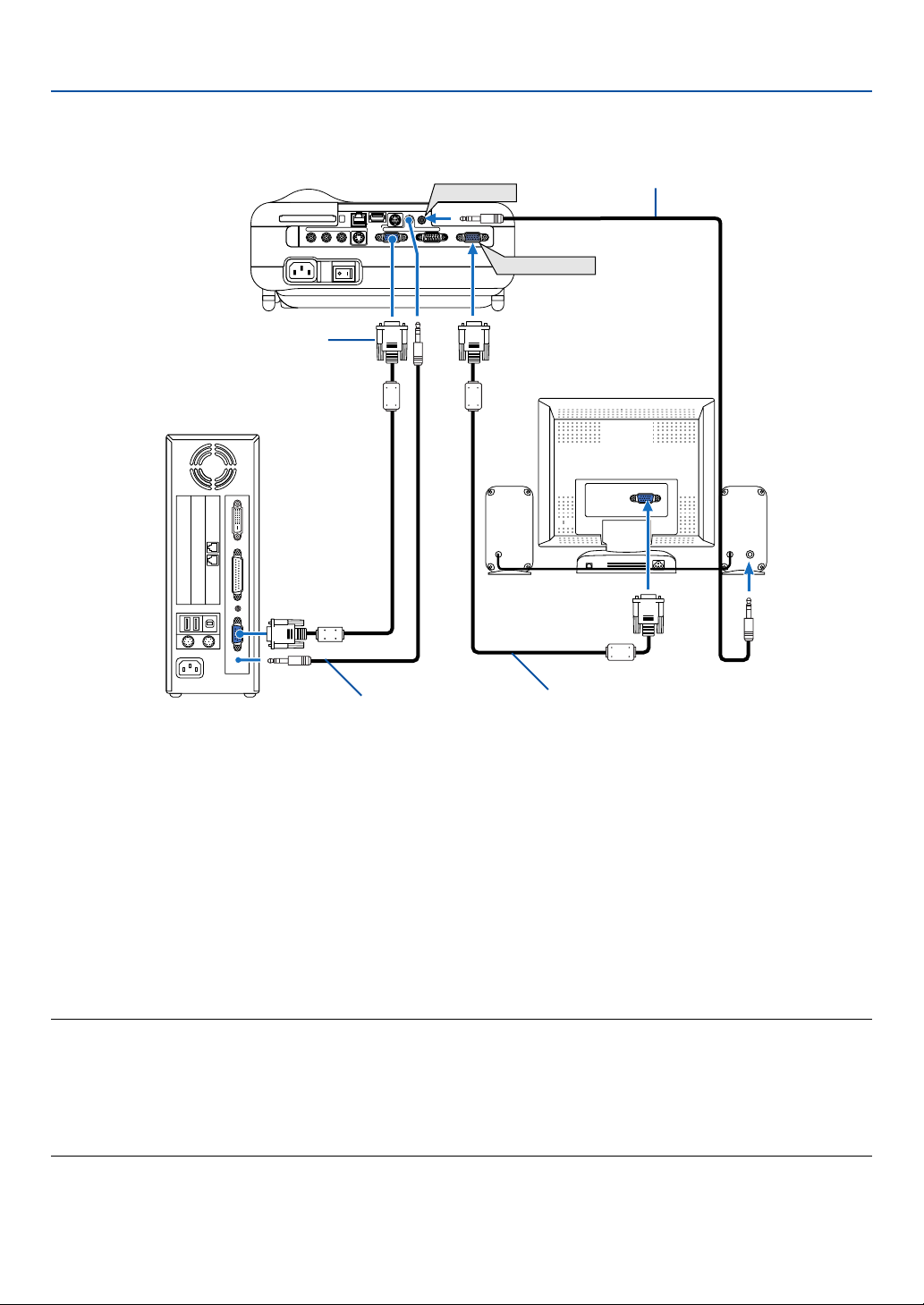
Connecting an External Monitor
2. Installation and Connections
PC CARD
R AUDIO IN L
AC IN
RGB/VGA signal cable (supplied)
VIDEO IN
S-VIDEO IN
USBLAN
PC CONTROL
COMPUTER 1 IN COMPUTER 2 IN
AUDIO OUT
AUDIO IN
AUDIO OUT
MONITOR OUT
MONITOR OUT
Audio cable (not supplied)
AUDIO
IN
Audio cable (not supplied)
RGB/VGA signal cable (not supplied)
You can connect a separate, external monitor to your projector to simultaneously view on a monitor the RGB analog
image you're projecting.
To do so:
1. Turn off the power to your projector, monitor and computer.
2. Use an RGB/VGA signal cable to connect your monitor to the MONITOR OUT (Mini D-Sub 15 pin) connector on
your projector.
3. Connect the supplied power cable. See page 26.
4. Turn on the projector, monitor and the computer.
NOTE:
• The MONITOR OUT connector outputs an RGB signal during Standby mode.
• When the projector is in the standby mode, the image may not be correctly displayed while the cooling fans are running
immediately after turning on or off the power.
• Output sound level can be adjusted in accordance with the sound level.
• When audio equipment is connected, the projector speaker is disabled.
• Daisy chain connection is not possible.
19
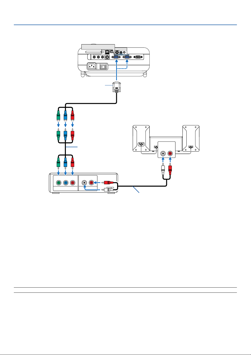
Connecting Your DVD Player with Component Output
2. Installation and Connections
COMPUTER 1 IN
PC CARD
R AUDIO IN L
AC IN
Optional 15-pin - to - RCA (female)⳯3 cable
(ADP-CV1)
Component video RCA⳯3
cable (not supplied)
DVD player
YCbCr
L R
VIDEO IN
S-VIDEO IN
USBLAN
PC CONTROL
COMPUTER 1 IN COMPUTER 2 IN
AUDIO OUT
MONITOR OUTAUDIO IN
Audio Equipment
AUDIO IN
LR
Component
AUDIO OUT
Audio cable (not supplied)
You can connect your projector to a DVD player with component output or Video output. To do so, simply:
1. Turn off the power to your projector and DVD player.
2. If your DVD player has a component video (Y,Cb,Cr) output, use a commercially available component video cable
(RCA⳯3) and the optional 15-pin-to-RCA (female)⳯3 cable to connect your DVD player to the COMPUTER IN
connector on the projector.
For a DVD player without component video (Y,Cb,Cr) output, use an S-Video cable (not provided) to connect an SVideo output of the DVD player to the Video Input of the projector.
3. Connect the supplied power cable. See page 26.
4. Turn on the projector and DVD player.
A component signal will be automatically displayed. If not, from the menu, select [Setup] → [Options] → [Signal
Select] → [Computer 1 (or 2)] → [Component].
NOTE: Refer to your DVD player's owner's manual for more information about your DVD player's video output requirements.
20
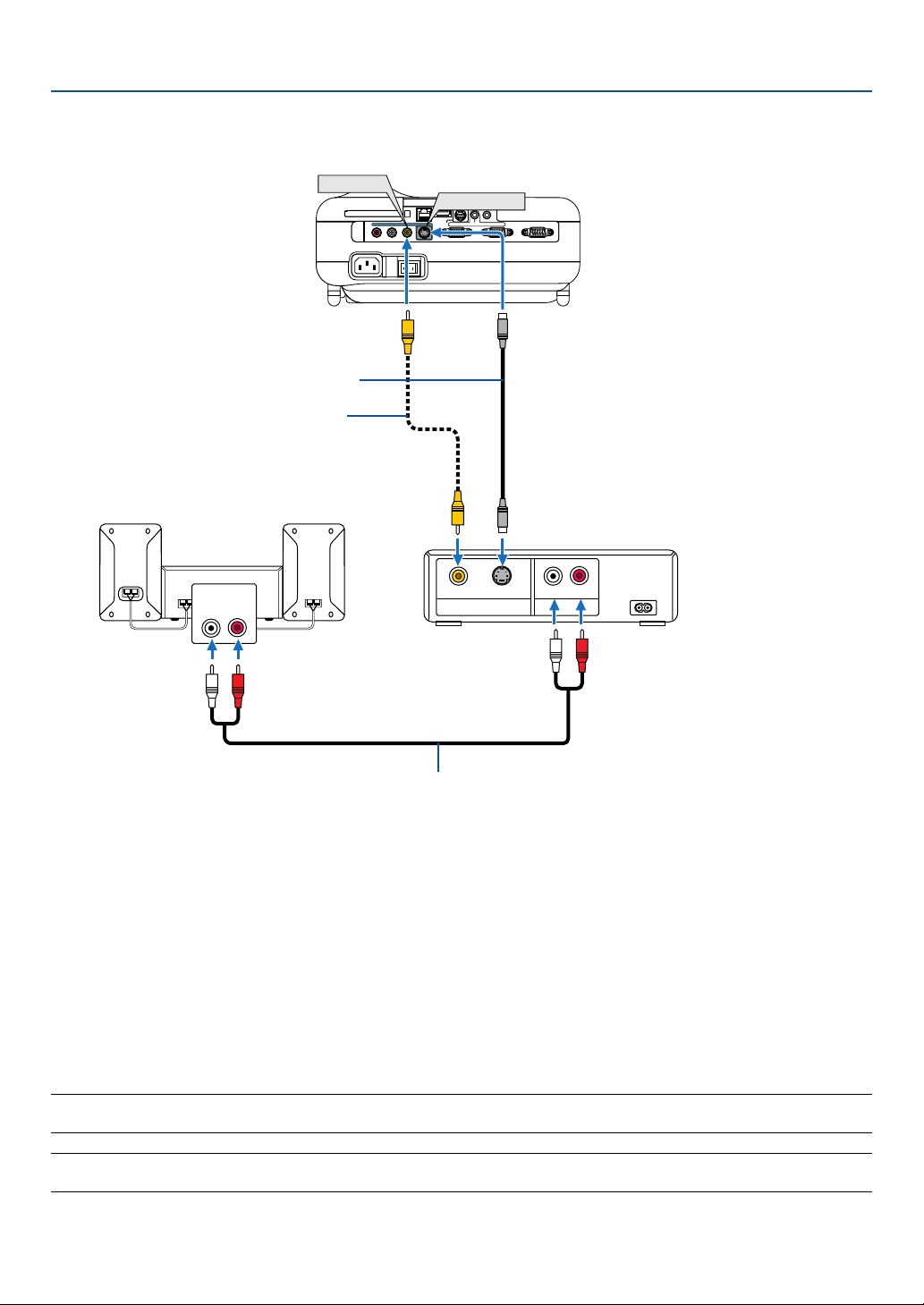
Connecting Your VCR or Laser Disc Player
2. Installation and Connections
S-Video cable (not supplied)
Video cable (not supplied)
Audio equipment
AUDIO IN
LR
VIDEO IN
PC CARD
R AUDIO IN L VIDEO IN MONITOR OUT
S-VIDEO IN
AC IN
S-VIDEO IN
AUDIO OUT
USBLAN
PC CONTROL
COMPUTER 1 IN COMPUTER 2 IN
AUDIO IN
S-VIDEOVIDEO
VIDEO OUT
VCR/ Laser disc player
L R
AUDIO OUT
Audio cable (not supplied)
Use an RCA or S-Video cable (not provided) to connect the video and use RCA cables (not provided) to connect
the audio from your VCR, laser disc player or document camera to your projector.
To make these connections, simply:
1. Turn off the power to the projector and VCR, laser disc player or document camera.
2. Connect one end of an RCA cable to the video output (or one end of an S-Video cable to the S-Video output
connector) on the back of your VCR or laser disc player, connect the other end to the appropriate video input on
your projector. Connect one end of a pair RCA cables (not supplied) to the audio output on the back of your VCR or
laser disc player, connect the other end to your audio equipment or to the appropriate audio input on the projector.
3. Connect the supplied power cable. See page 26.
4. Turn on the projector and the VCR or laser disc player.
NOTE: Refer to your VCR or laser disc player owner's manual for more information about your equipment's video output
requirements.
NOTE: An image may not be displayed correctly when a Video or S-Video source is played back in fast-forward or fast-rewind via
a scan converter.
21
2. Installation and Connections
Connecting to a Network
The LT265/LT245 comes standard with a LAN port (RJ-45) which provides a LAN connection using a LAN cable.
Placing the optional wireless LAN card (NWL-100*) in the PC card slot of the projector also provides a wireless LAN
connection. To use a LAN connection, you are required to assign an IP address to the projector. For setting the LAN
mode, see page 99 (From the menu, select [Setup] → [Installation] → [LAN Mode])
With the LAN connection, two features are available: Projector control and Picture transmission.
Projector control feature
With the wired or wireless LAN connection, you can control (power on/off, input select, etc.) and receive information
from the projector over the network using a computer. The following two methods are available:
* Using the HTTP Server feature on the projector. See page 54.
* Using PC Control Utility 3.0 from the supplied User Supportware 2 CD-ROM.
Picture transmission feature
With the wired or wireless LAN connection, you can send images and slides from a personal computer to the projector
which then can be projected on the screen. The following two methods are available:
* Using Image Express Utility 2.0 from the supplied User Supportware 2 CD-ROM.
* Using Ulead Photo Explore 8.0 from the supplied User Supportware 2 CD-ROM.
With the USB mouse connected to the projector, you can also operate the desktop screen on your Windows PC
connected to the LAN or the wireless LAN.
* Using Desktop Control Utility 1.0 from the supplied User Supportware 2 CD-ROM.
NOTE: For information about the five software utilities (Image Express Utility 2.0, Desktop Control Utility 1.0, Ulead Photo
Explorer 8.0, Viewer PPT Converter and PC Control Utility 3.0) contained on the supplied Projector User Supportware 2.0 CDROM, see the supplied “NEC Software Utility Installation Guide”. See also each online help of the software utilities for information
about their functions and operations.
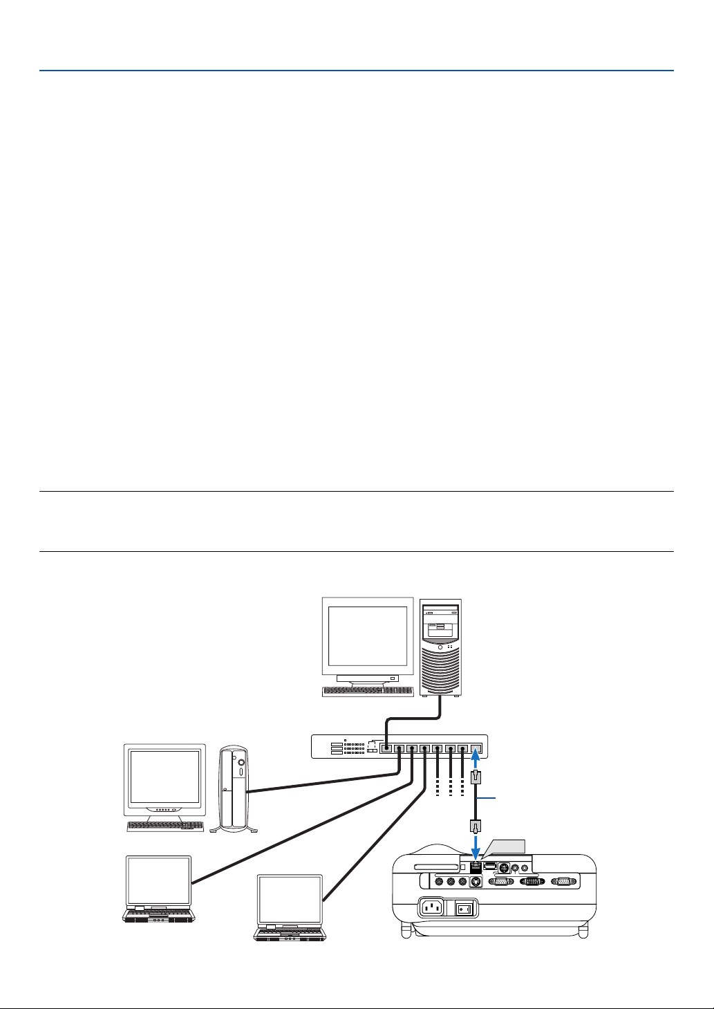
Example of LAN connection
(A) Example of wired LAN connection
Server
PC CARD
Hub
LAN cable (not supplied)
LAN
AUDIO OUT
VIDEO IN
S-VIDEO IN
PC CONTROL
USBLAN
COMPUTER 1 IN COMPUTER 2 IN
AUDIO IN
MONITOR OUT
R AUDIO IN L
AC IN
22
2. Installation and Connections
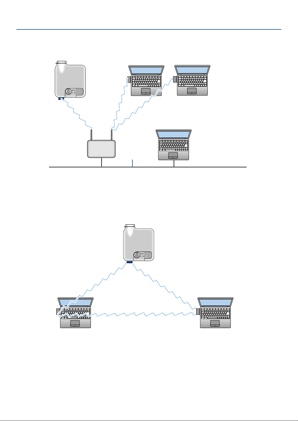
(B) Example of wireless LAN connection
(Network Type → Mode: Infrastructure)
Access Point
Wired LAN
To make connection with a wired LAN via an access point, you need to select the Infrastructure mode.
From the menu, select [Setup] → [Installation] → [LAN Mode] → [PC Card] → [Advanced] → [Network Type] →
[Infrastructure].
(C) Example of wireless LAN connection (Network Type → Mode: 802.11 Ad Hoc)
To enable direct communication (i.e., peer-to-peer) between personal computers and projectors, you need to
select the 802.11 Ad Hoc mode.
From the menu, select [Setup] → [Installation] → [LAN Mode] → [PC Card] → [Advanced] → [Network Type] →
[802.11 Ad Hoc].
The 802.11 Ad hoc mode complies with IEEE802.11 standard.
When in Ad Hoc mode, only 802.11b is available for communication method.
Data transmission speed in Ad Hoc mode is limited up to 11Mbps.
23
Loading...