


FUEL 3100
Table of contents
 Loading...
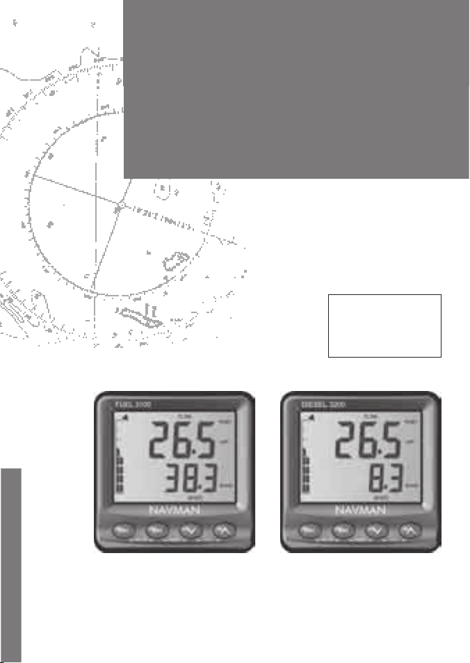
Installation and
Operation Manual
NAVMAN
w w w . n a v m a n . c o m
Pilot 3380
A U T O P I L O T
FUEL 3100 (Petrol)
and
DIESEL 3200 (Diesel)
F U E L M O N I T O R S
English ................ 3
Español ............. 27
Português .........51
FUEL 3100 DIESEL 3200

Units
This instrument is set up with units of US Gallons, knots and nautical miles.
Please refer to section 2-7 to change the units.
FCC Statement
Note: This equipment has been tested and found to comply with the limits for a Class
B digital device, pursuant to Part 15 of the FCC Rules. These limits are designed to
provide reasonable protection against harmful interference in a normal installation.
This equipment generates, uses and can radiate radio frequency energy and, if not
installed and used in accordance with the instructions, may cause harmful interference
to radio communications. However, there is no guarantee that interference will not
occur in a particular installation. If this equipment does cause harmful interference to
radio or television reception, which can be determined by turning the equipment off
and on, the user is encouraged to try to correct the interference by one or more of the
following measures:
• Re-orient or relocate the receiving antenna.
• Increase the separation bet ween the equipment and receiver.
• Connect the equipment into an output on a circuit dif ferent from that to which
the receiver is connec ted.
• Consult the dealer or an experienced technician for help.
• A shielded cable must be used when connecting a peripheral to the serial por ts.

Contents
1 Introduction ..........................................................................................................................................6
1-1 Typical Installations . . . . . . . . . . . . . . . . . . . . . . . . . . . . . . . . . . . . . . . . . . . . . . . . . . . . . . . . . . . . . . .6
1-2 How the flow sensors work . . . . . . . . . . . . . . . . . . . . . . . . . . . . . . . . . . . . . . . . . . . . . . . . . . . . . . . 7
1-3 Cleaning and maintenance . . . . . . . . . . . . . . . . . . . . . . . . . . . . . . . . . . . . . . . . . . . . . . . . . . . . . . . 7
1-4 Calibration . . . . . . . . . . . . . . . . . . . . . . . . . . . . . . . . . . . . . . . . . . . . . . . . . . . . . . . . . . . . . . . . . . . . . . . 7
2 Operation ..............................................................................................................................................7
2-1 Turning on and off . . . . . . . . . . . . . . . . . . . . . . . . . . . . . . . . . . . . . . . . . . . . . . . . . . . . . . . . . . . . . . . .7
2-2 The Keys . . . . . . . . . . . . . . . . . . . . . . . . . . . . . . . . . . . . . . . . . . . . . . . . . . . . . . . . . . . . . . . . . . . . . . . . . . 7
2-3 Setting the backlight . . . . . . . . . . . . . . . . . . . . . . . . . . . . . . . . . . . . . . . . . . . . . . . . . . . . . . . . . . . . . 8
2-4 Upper display . . . . . . . . . . . . . . . . . . . . . . . . . . . . . . . . . . . . . . . . . . . . . . . . . . . . . . . . . . . . . . . . . . . . 8
2-5 Lower display . . . . . . . . . . . . . . . . . . . . . . . . . . . . . . . . . . . . . . . . . . . . . . . . . . . . . . . . . . . . . . . . . . . . . 8
2-6 Fuel and battery alarms . . . . . . . . . . . . . . . . . . . . . . . . . . . . . . . . . . . . . . . . . . . . . . . . . . . . . . . . . .9
2-7 Fuel gauge . . . . . . . . . . . . . . . . . . . . . . . . . . . . . . . . . . . . . . . . . . . . . . . . . . . . . . . . . . . . . . . . . . . . . . .9
2-8 Changing fuel units . . . . . . . . . . . . . . . . . . . . . . . . . . . . . . . . . . . . . . . . . . . . . . . . . . . . . . . . . . . . . . 9
2-9 Simulation mode . . . . . . . . . . . . . . . . . . . . . . . . . . . . . . . . . . . . . . . . . . . . . . . . . . . . . . . . . . . . . . . . .9
2-10 Key reference . . . . . . . . . . . . . . . . . . . . . . . . . . . . . . . . . . . . . . . . . . . . . . . . . . . . . . . . . . . . . . . . . . .10
3 The setup menus .................................................................................................................................. 11
3-1 Setup data . . . . . . . . . . . . . . . . . . . . . . . . . . . . . . . . . . . . . . . . . . . . . . . . . . . . . . . . . . . . . . . . . . . . . . . 11
3-2 Initial Setup . . . . . . . . . . . . . . . . . . . . . . . . . . . . . . . . . . . . . . . . . . . . . . . . . . . . . . . . . . . . . . . . . . . . . 11
3-3 Setup Menus and data . . . . . . . . . . . . . . . . . . . . . . . . . . . . . . . . . . . . . . . . . . . . . . . . . . . . . . . . . . .12
3-4 Fuel calibration (CAL.F) . . . . . . . . . . . . . . . . . . . . . . . . . . . . . . . . . . . . . . . . . . . . . . . . . . . 14
3-5 Fuel flow damping (dAmP.F) . . . . . . . . . . . . . . . . . . . . . . . . . . . . . . . . . . . . . . . . . . . . . . 14
3-6 Speed input (InPUt) . . . . . . . . . . . . . . . . . . . . . . . . . . . . . . . . . . . . . . . . . . . . . . . . . . . . . 14
3-7 Speed damping (dAmP.S) . . . . . . . . . . . . . . . . . . . . . . . . . . . . . . . . . . . . . . . . . . . . . . . . . 14
3-8 Speed calibration by log (CAL.L) . . . . . . . . . . . . . . . . . . . . . . . . . . . . . . . . . . . . . . . . . . 15
3-9 Speed calibration by boat speed (CAL.S) . . . . . . . . . . . . . . . . . . . . . . . . . . . . . . . . . . . 15
4 Installation .......................................................................................................................................... 16
4-1 Tank and engine options . . . . . . . . . . . . . . . . . . . . . . . . . . . . . . . . . . . . . . . . . . . . . . . . . . . . . . . .16
4-2 The display unit . . . . . . . . . . . . . . . . . . . . . . . . . . . . . . . . . . . . . . . . . . . . . . . . . . . . . . . . . . . . . . . . .17
4-3 The fuel flow sensor(s) . . . . . . . . . . . . . . . . . . . . . . . . . . . . . . . . . . . . . . . . . . . . . . . . . . . . . . . . . . .17
4-4 The speed sensor (optional) . . . . . . . . . . . . . . . . . . . . . . . . . . . . . . . . . . . . . . . . . . . . . . . . . . . . .17
4-5 Power/data cable wiring . . . . . . . . . . . . . . . . . . . . . . . . . . . . . . . . . . . . . . . . . . . . . . . . . . . . . . . . .18
4-6 Systems of several instruments . . . . . . . . . . . . . . . . . . . . . . . . . . . . . . . . . . . . . . . . . . . . . . . . . . 19
4-7 Testing the installation . . . . . . . . . . . . . . . . . . . . . . . . . . . . . . . . . . . . . . . . . . . . . . . . . . . . . . . . . .20
4-8 Resetting to factory defaults . . . . . . . . . . . . . . . . . . . . . . . . . . . . . . . . . . . . . . . . . . . . . . . . . . . .20

5 When you add or remove fuel ...............................................................................................................20
6 Troubleshooting .................................................................................................................................. 21
Appendix A Specifications .......................................................................................................................23
Appendix B Diesel fuel flow sensor hardware ..........................................................................................24
B-1 FUEL 3100 . . . . . . . . . . . . . . . . . . . . . . . . . . . . . . . . . . . . . . . . . . . . . . . . . . . . . . . . . . . . . . . . . . . . . . .24
B-2 DIESEL 3200 . . . . . . . . . . . . . . . . . . . . . . . . . . . . . . . . . . . . . . . . . . . . . . . . . . . . . . . . . . . . .24
B-3 Other options (FUEL 3100 and DIESEL 3200) . . . . . . . . . . . . . . . . . . . . . . . . . . . . . . . . . . . . .25
Appendix C - Speed through water and over ground ................................................................................26

It is the owner’s sole responsibility to install and use the instrument and its sensor(s) in a manner
that will not cause accidents, personal injury or property damage. The user of this product is solely
responsible for observing safe boating practices.
Fuel type: Navman petrol flow sensors (plastic) and FUEL 3100 instruments have been specifically
developed for use in marine applications with petrol (gasoline) inboard and outboard engines and
are not warranted for any other type of application. These sensors and instruments must NOT be
used with petrol EFI engines with a return line to the tank or with diesel engines.
Navman diesel flow sensors (metal) and DIESEL 3200 instruments have been specifically developed
for use in marine applications with diesel engines and are not warranted for any other type of
application. These sensors and instruments must NOT be used with petrol (gasoline) engines.
Fuel formulation: Every effort has been made by the manufacturer to ensure that the materials
used in the Navman fuel flow sensor(s) will operate reliably with different fuel mixtures. The
manufacturer or its distributors can not be held responsible for fuel formulation or any affect this
may have on the performance and durability of the fuel flow sensor(s).
Back pressure: A fuel flow sensor will create additional back pressure in a fuel system:
• In a petrol system (FUEL 3100): 1/2" of mercury at 19.8 US gallons /hour (75 litres/ hour) and 1"
of mercury at 39.5 US gallons per hour (150 litres/ hour).
• In a diesel system (DIESEL 3200): 0.3" of mercury at 25 US gallons /hour (100 litres/ hour) and
1.5" of mercury at 80 US gallons per hour (300 litres/hour).
It is the owners responsibility to ensure that fitting the fuel flow sensor(s) does not cause fuel
starvation which may lead to poor engine performance.
Fuel Computer: Fuel economy can alter drastically depending on the boat loading and sea
conditions. The fuel computer should not be the sole source of information concerning available
fuel onboard and the electronic information should be supplemented by visual or other
checks of the fuel load. This is necessary due to possible operator induced errors such as forgetting
to reset the fuel used when filling the tank, running the engine with the fuel computer not
switched on or other operator controlled actions that may render the device inaccurate. Always
ensure that adequate fuel is carried onboard for the intended trip plus a reserve to allow for
unforeseen circumstances.
Specific requirements: Your boat’s fuel installation boat might be subject to specific requirements
(such as USCG, NMMA and ABYC guidelines or local laws), particularly if the boat is licensed,
surveyed, charted or inspected. It is the owner’s sole responsibility to install and use the instrument
and its sensor(s) in compliance with these requirements.
NAVMAN NZ LIMITED DISCLAIMS ALL LIABILITY FOR ANY USE OF THIS PRODUCT IN A WAY THAT
MAY CAUSE ACCIDENTS, DAMAGE OR THAT MAY VIOLATE THE LAW.
Governing Language: This statement, any instruction manuals, user guides and other information
relating to the product (Documentation) may be translated to, or has been translated from,
another language (Translation). In the event of any conflict between any Translation of the
Documentation, the English language version of the Documentation will be the official version of
the Documentation.
This manual represents the FUEL 3100 and DIESEL 3200 as at the time of printing. Navman NZ
Limited reserves the right to make changes to specifications without notice.
Copyright © 2004 Navman NZ Limited, New Zealand. All rights reserved. Navman is a registered
trademark of Navman NZ Limited.
Important
6
FUEL 3100 / DIESEL 3200 Installation and Ope ration Manual
NAVMA N
This manual describ es two different Navman
marine fuel instruments:
• The FUEL 3100, which is installed with the
separate petrol/ gasoline flow sensor kit,
and measures petrol consumption.
• The DIESEL 3200, which is installed with
the separate diesel flow sensor kit, and
measures diesel consumption.
This manual describ es how to install, set up and
operate the instruments. For more information,
refer to the separate Flo w Sensor Installation
Manual (for the FUEL 3100 and petrol systems)
and Diesel Fl ow Sensor Installation a nd
Operatio n Manual (for the DIESEL 3200 and
diesel systems); this manual has extensive
information on understanding and optimising
your diesel boat’s performance.
The FUEL 3100 or DIESEL 3200 measures and
displays the fuel flow in real time for a single or
twin engine boat. It can calculate and display
the amount of fuel used, the amount of fuel
remaining and the fuel flow rate.
If an optional speed sensor or speed
instrument is connected, the unit can also
1 Introduction
show the fuel economy, boat speed and the
trip log and total logs.
Knowing the fuel economy can help determine
the optimum throttle settings and maximize
fuel savings. With twin engine boats,
comparison between the flow rates of each
engine can be used to achieve maximum
synchronisation.
It is essential to update the fuel readings in
the FUEL 3100 or DIESEL 3200 after a partial or
full refill, or af ter manually removing fuel, to
maintain accurate readings (see section 5).
The FUEL 3100 and DIESEL 3200 are par t of
the Navman family of instruments for boats,
which includes instruments for speed, depth,
wind and repeaters. These instruments can be
connected together, using NavBus or NMEA , to
form an integrated data system for a boat.
Information in this manual applies to both the
FUEL 3100 and the DIESEL 3200 unless noted. It
is vital to read this document and the Navman
instrument’s installation and operation manual
before installing or using this kit.
Power supply
Sensor wiring
Connection to other
instruments (optional)
Petrol tank
Diesel tank
Diesel engine
Tachometer pickup
Power supply
Sensor wiring
Connection to other
instruments (optional)
Diesel flow
sensor
Diesel flow
sensor
Petrol flow sensor
Petrol engine
1-1 Typical Installations
FUEL 3100 System
DIESEL 3200 System
In a twin engine system, each
engine has its own sensor(s)
7
FUEL 3100 / DIESEL 3200 Installation and Ope ration Manual
NAVMA N
2 Operation
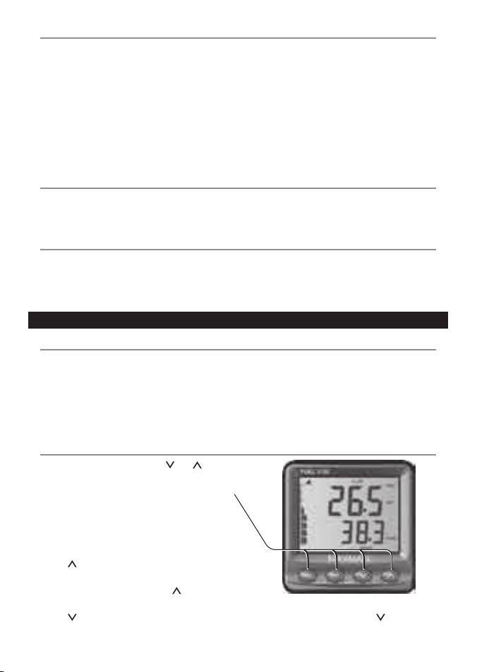
The unit has four keys, ESC , ENT, and .
In this manual:
• Press means push the key for less than one
second.
• Hold means hold the key down until the
display changes.
In general:
• Press to change what is displayed in the
upper display.
In a setup menu, press or hold to
increase the setting.
• Press to change what is displayed in the
lower display.
Petrol flow sensor (FUEL 3100): The petrol
flow sensor is fitted in the fuel line between the
fuel tank and the engine. A small turbine inside
the fuel f low sensor measures the rate of the
fuel flow into the engine. This information is
relayed through the fuel flow sensor cable and
shown electronically on the display unit.
Diesel flow sensor (DIESEL 3200): A diesel
sensor is a positive displacement flowmeter,
with one moving internal part, made of low
friction, fuel proof plastic. There are no fine
pointed shafts and jewelled bearings to get
worn or hammered by diesel pulsing.
Each engine is fit ted with two fuel flow
sensors, to measure fuel supply and return.The
system calculates the engine consumption,
compensating for pulsing from diaphragm
lift pumps, dif ferent fuel temperatures in
the supply and return lines and the flow
characteristic s of the sensors.
Clean the display unit and any plastic sensor
with a damp cloth or mild detergent. Avoid
abrasive cleaners, petrol or other solvents.
1-2 How the flow sensors work
1-3 Cleaning and maintenance
1-4 Calibr ation
Put the protective cover over the display when
it is not being used.
FUEL 3100: It is essential to calibrate the fuel
flow sensors af ter installation and again af ter
the first 100 engine hours to allow moving
parts to wear in (see section 3-4).
DIESEL 3200: The sensors are factor y
calibrated and are highly accurate. They can be
calibrated but this should not be necessary.
2-2 The Keys
2-1 Turning on and off
The display unit does not have its own power
switch, but if possible should be wired so that it
turns on when the engine ignition is turned on
to allow the engine hours counter to function
properly. (See sec tion 4 -5).
Turn the unit on and off with the boat ’s ignition
switch. The display unit does not have its own
power switch. When the unit it is turned off,
any settings you have made are retained.
If SIM flashes at the bottom left corner of the
display, the unit is in simulation mode (see
section 2-9).
In a setup menu, press or hold to decrease
the setting.
8
FUEL 3100 / DIESEL 3200 Installation and Ope ration Manual
NAVMA N
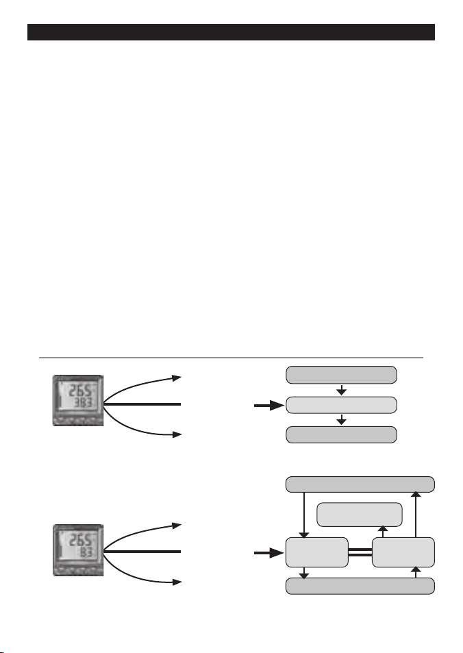
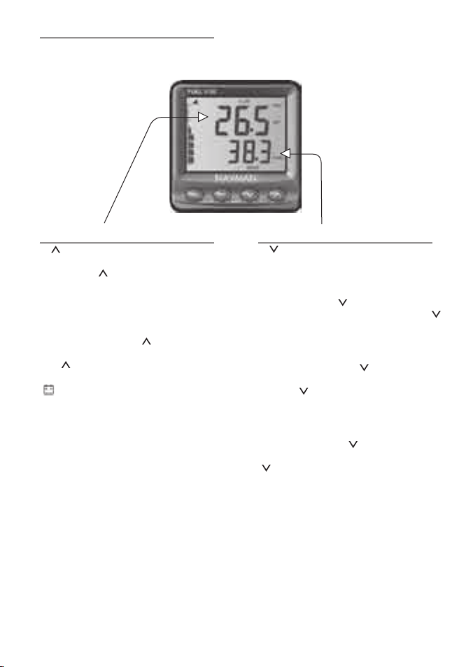
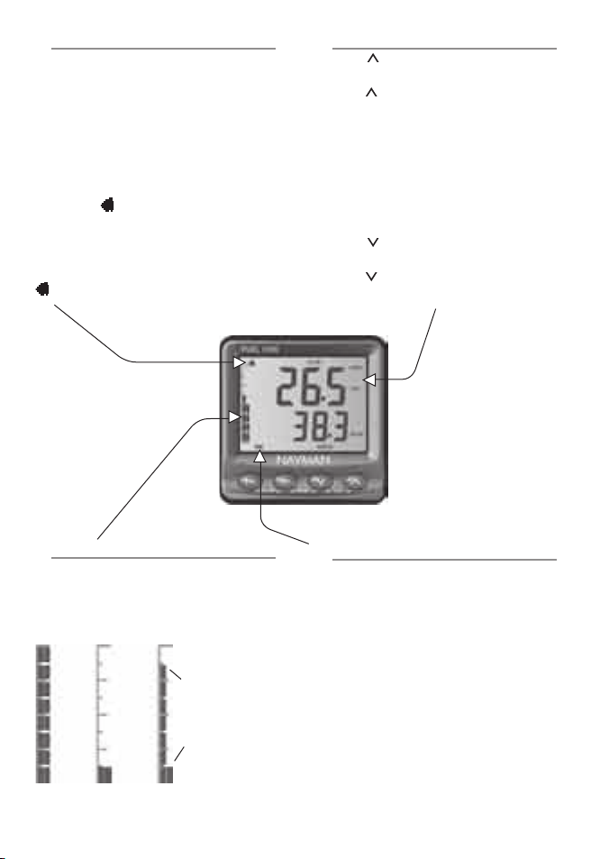
2-4 Upper display
Press one or more times to change what is
displayed (for example, if the display shows
USED then press to change the display to
FLOW):
• REMAINING: Fuel remaining. Update this
when you add or remove fuel (see section 5).
• USED : The fuel used since last reset.
To reset fuel used, press one or more
times until used is displayed, then hold ENT
and together until the reading resets
to zero.
• : Displays supply voltage to the head unit.
• FLOW: Fuel flow rate.
• ECONOMY: Distance travelled per unit of
fuel used (requires optional speed input, see
section 3-6)
• RPM: Engine RPM (DIESEL 3200 only).
PORT RPM: Port engine RPM (displayed on
upper display)
STBD RPM: Starboard engine RPM
(displayed on lower display)
Note:
• If the boat has twin engines, then when
FLOW is displayed, press ENT one or more
times to display PORT, STBD or TOTAL
flow.
• If the boat has a twin fuel tank s, then when
REM AINING or USED is displayed, press
ENT one or more times to display PORT,
STBD or TOTAL data.
2-5 Lower display
Press one or more times to change what
is displayed:
• LOG: Trip distance; the distance travelled
since log was reset.
To reset log, press one or more times
until log is displayed, then hold ENT and
together until the reading resets to zero.
• TOTAL LOG : Total distance; the distance
travelled since total log was reset.
To reset total log, press one or more
times until total log is displayed, then hold
ENT and together until the reading
resets to zero.
• hours: Hours the engine has run since
hours was reset.
To reset hours, press one or more times
until hours is displayed, then hold ENT and
together until the reading resets to zero.
• RANGE: Estimated distance that can be
travelled on the remaining fuel at the
current consumption.
• SPEED: Boat speed.
Note:
• LOG, TOTAL L OG, RANGE and SPEED
require the optional speed input (see
section 3-6).
The display and keys are backlit for easy
reading in dim light. To change the backlight,
change L AmP in the LA mP menu.
(see sec tion 3-3)
2-3 Setting the b acklight
9
FUEL 3100 / DIESEL 3200 Installation and Ope ration Manual
NAVMA N
2-8 Changing fuel units
1 Press until REMAINING, USED, FLOW or
ECONOMY are displayed.
2 Hold one or more times to change fuel
units.
Note:
When “gal” is displayed, this could be US
gallons or imperial gallons. Check the units
menu to conf irm and change if required
(see FUEL UnItS in the UnItS menu,
section 3-3).
Changing distance and speed units
1 Press until LOG, TOTAL LOG, R ANGE
or SPEED are displayed.
2 Hold one or more times to change
distance and speed units.
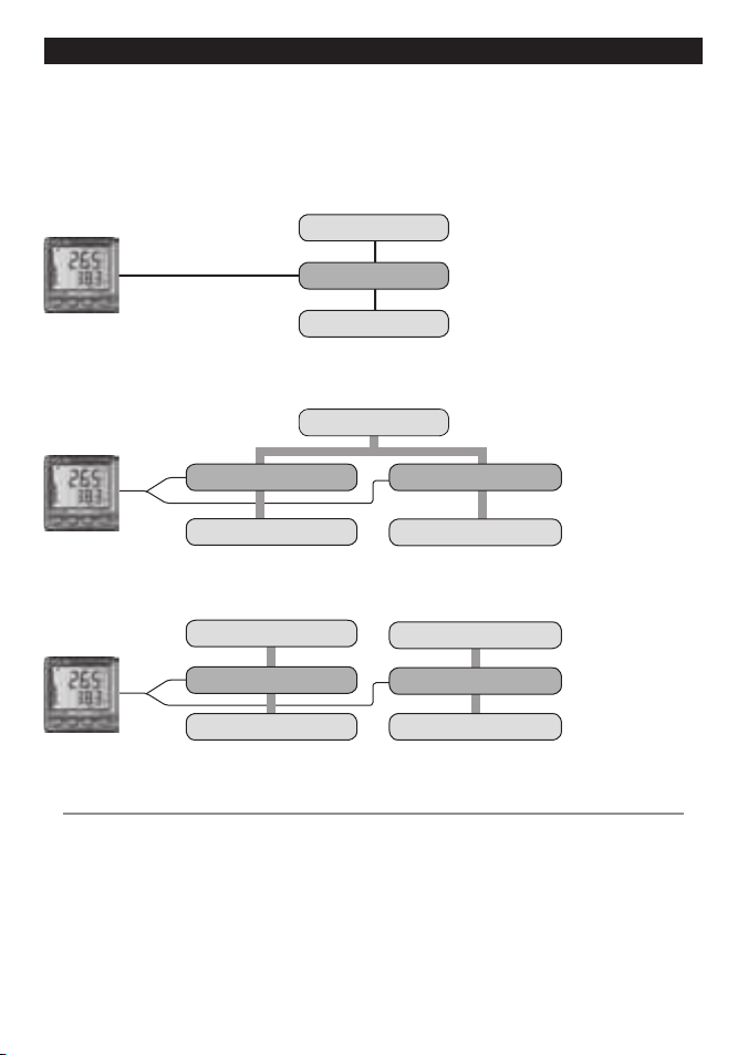
2-7 Fuel gauge
Displays fuel remaining in the tank(s). If the
boat has twin tank s, the gauge shows both
tanks; the left side is the port tank and the right
side the starboard tank:
Single tank Twin tanks
Full
Port tank
almost full
Starboard tank
almost empty
2-6 Fuel and bat tery alarms
The unit has two alarms:
• Low fuel: Alarm sounds when the fuel left
in the tank becomes less than the alarm
value.
• Low battery: Alarm sounds when the
batter y voltage becomes less than the
alarm value.
To turn the alarms on and off and to set the
alarm values, see section 3-3. When an alarm
sounds, the symbol flashes, the internal
beeper sounds and any external beepers or
lights operate. For a low fuel alarm the fuel
gauge flashes.
Press ESC to mute the alarm.
alarm symbol
2-9 Simulatio n mode
Simulation mode allows the user to become
familiar with the FUEL 3100 off the water. In
Simulation mode, the FUEL 3100 generates
data internally and ignores input from the
sensor. The word SIM flashes at the bottom left
corner of the display.
To turn Simulation mode on or off:
1 Turn the power off.
2 Hold ESC while turning the power on.
Almost
Empty
10
FUEL 3100 / DIESEL 3200 Installation and Ope ration Manual
NAVMA N
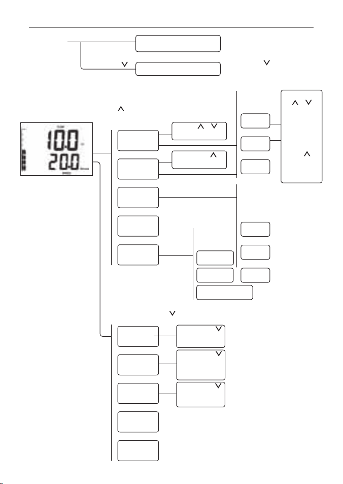
Hold ENT +
for 5 s to reset
TOTAL LOG
Press ENT + to
reset USED
2-10 Key reference
FUEL
REMAINING
FUEL USED
FUEL FLOW
FUEL
ECONOMY*
LOG *
TOTAL
LOG*
hours
RANGE*
SPEED*
Hold ENT +
for 5 s to reset
hours
Press ENT +
to reset LOG
Press +
when tank filled
Press
+
when tank
filled
When USED
displayed,
press
ENT + to
reset USED
Reset to factory defaults
Turn Simulation mode On
or OFF
*Hold ENT +
Upper display
Press to change what is displayed
PORT
STBD
TOTAL
PORT
STBD
TOTAL
Single tank
Hold ESC
Lower display Press to change what is displayed
When unit is
turned on
Main display
RPM PORT
RPM STBD
Twin engines
press ENT to
display:
RPM
Diesel only
PORT and STBD
* denotes must have speed input (see section 3-6)
*Hold ENT + for at
least 5 seconds.
Twin engines
press ENT
to display:
Twin engines
press ENT
to display:

11
FUEL 3100 / DIESEL 3200 Installation and Ope ration Manual
NAVMA N
3 The setup menus
3-1 Setup data
Use the setup menus, shown on the following
pages, to customize the unit to suit your
boat and your own preferences. To display or
change setup data:
1 From the main display, press ESC and ENT
together to start setup mode.
2 Press or one or more times to display
the setup menus.
3 Press ENT to select a setup menu.
4 Press or one or more times to display
the setup data for the setup menu.
5 If the boat has twin engines or twin tanks,
press ENT. Press one or more times to
display the port or starboard setup data.
6 To change the data:
i Press ENT; the data will blink.
ii Press or hold or to change the
value.
iii Press ENT to accept the new value or
press ESC to ignore your changes.
7 To display or change other setup data for
this setup menu, repeat steps 4, 5 and 6.
Then press ESC.
8 To display or change setup data for other
setup menus, repeat steps 2 to 6. Finally,
press ESC to return to the main display.
3-2 Initial Setup
1 In the FUEL menu set up the number of
fuel tanks. Select dUA L then Off (1 tank)
or On (2 tank s).Then select the number of
engines. Motor (1 or 2).
2 In the dSL SEn Menu identify the motors
by:
i Reset to single engine installation.
ii Select one motor (port or starboard),
then remove p ower from the
other motor’s diesel f low sensor
by unplugging the white coloured
connector.
iii Press and hold ENT for 2 seconds to
configure the motor, a beep will sound
when complete.
Repeat ii and iii for the other motor.
3 In the SPEEd menu identif y the speed
input.None, GPS or Sen.
4 To reset all data to the factory defaults see
section 4-8
5 For single engine/ single tank diesel
installation fac tory defaults will work.
12
FUEL 3100 / DIESEL 3200 Installation and Ope ration Manual
NAVMA N
FUEL
Set fuel in tank(s) when
you add or remove fuel
(see section 5)
Twin tanks: section 3-1
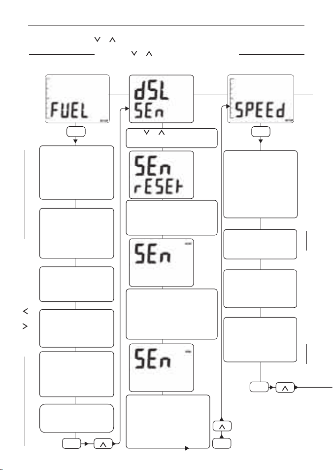
3-3 Setup Menus a nd data
From the main display, press ENT + ESC together
to start setup mode. Press or until desired
menu is desplayed then press ENT to select it.
Press ESC again to return to the main menu.
Speed menuFuel menu
dUAL
Set number of fuel tanks
Off: 1 tank
On: 2 tanks
See section 3-2
SIZE
Set capacity of fuel
tank(s)
See section 3-3
motor
Set number of engines,
1 or 2
See section 3-1
CAL .F
Calibrate fuel sensor(s)
(see section 3-4)
Twin engines:
See section 3-3
dA mP.F
Set fuel damping
see section 3-5)
InPUt
Select speed input:
No: None
GPS: GPS/NMEA
SEn: Paddlewheel
sensor (see section3-6)
dA mP.S
Set speed damping (see
section 3-7)
CAL .L
Calibrate speed sensor
from log (see section
3-8)
CAL .S
Calibrate speed sensor
from boat speed
(see section 3-9)
Press or to select a setup menu
Press or to select setup data
Only available if InPUt = SEn
See also section 4-1
Select port or starboard engine
Press ENT for 2 secs to reset
to single engine installation.
A BEEP will sound when
complete.
Power port sensor only.
See section 3-2.
Press and hold ENT for
2 seconds to configure port
screen to port sensor. A BEEP
will sound when complete.
Press or to view
screens below.
Power starboard sensor
only. See section 3-4.2.
Press ENT for 2 seconds to
configure starboard screen
to starboard sensor. A BEEP
will sound when complete.
ENT
ENT
ESC
ESC
ESC
13
FUEL 3100 / DIESEL 3200 Installation and Ope ration Manual
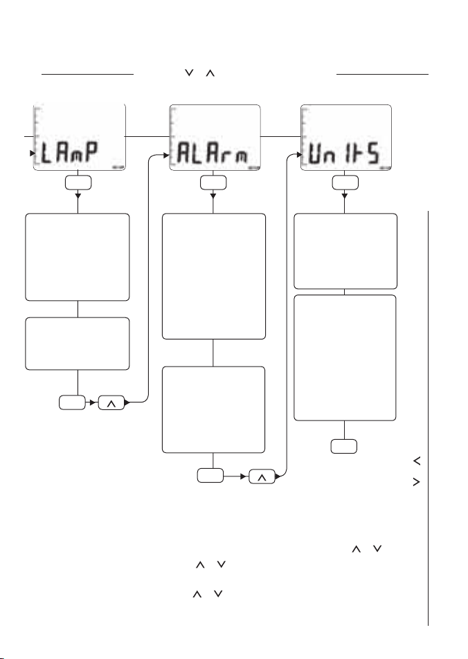
NAVMA N
Start setup mode press ENT + ESC together
Move to the desired menu by using or
Select the menu by pressing ENT
Move to the desired page by using or
Select the page press ENT
Units menuAlarm menu
Low .F
Set low fuel alarm:
0: Alarm off
Greater than 0: Set alarm
value
(see section 2-6)
Twin tanks:
see section 3-1
Low .b
Set low battery alarm:
0: Alarm off
Greater than 0: Set alarm
value
(see section 2-6)
Press or to select setup data
FUEL UnItS
Set fuel units:
GAL US, or
GAL ImP, or
LItrE
dISt UnItS
Set distance units:
nAUt mILES, or
StAT mILES
Distance units are used
for the log and for
the speed, eg setting
units to nAUt mILES
displays speed in knots
Lamp menu
LAm P
Set backlight for keys
and display:
0: Off
1: Dimmest
4: Brightest
GrouP
Set backlight group
number: 0 to 4
(see section 4-6
ENT
ENT
ENT
Press or to select a setup menu
Change the data press or
Accept the change press ENT
Leave the page press ESC
Return to the main display press ESC
Sequence of key strokes
ESC
ESC
ESC

14
FUEL 3100 / DIESEL 3200 Installation and Ope ration Manual
NAVMA N
3-4 Fuel calibration (CAL.F)
To calibrate a fuel flow sensor, select CAL.F in
the FUEL menu. Calibrate the sensors if you are
doubtful of their performance.
FUEL 3100: It is essential to calibrate the fuel
flow sensors af ter installation and again af ter
the first 100 engine hours to allow moving parts
to wear in.
DIESEL 3200: The sensors are factory calibrated
and are highly accurate. They can be calibrated
but this should not be necessary.
Calibrating a fuel flow sensor requires accurate
measurement of the fuel consumption. This is
best done using a small portable tank. At least 4
gallons (15 litres) of fuel should be used to ensure
an accurate calibration. The more fuel used, the
more accurate the calibration.
Twin engine boats require both engines to
be calibrated. Do these together with t wo
portable tanks, or at different times using one
portable tank.
To calibrate an engine’s fuel flow sensor:
1 Connect the portable tank to the
engine through the fuel flow sensor.
2 Reset USED:
i Press one or more times
until USED is displayed.
ii If your boat has twin tanks,
press ENT one or more times
to display PORT or STBD.
iii Hold ENT and together until
the reading resets to zero.
3 Run the engine at normal cruising
speed until a known amount of
fuel, at least 15 litres (4 gallons),
has been used per engine.
4 Select the FUEL setup menu, then
select CAL.F; if your boat has twin
engines, select the PORT or STBD engine
to be calibrated (see section 3-1).
5 If the value of CAL.F does not match
the known amount of fuel used, press
ENT, then press or and change
CAL.F until it does match. Then press
ENT to save the correct value (otherwise
press ESC to ignore the calibration).
3-5 Fuel flow damping (dAmP.F)
Waves and rocking of the boat cause the fuel
flow to fluctuate slightly. To give a stable reading,
the instrument calculates flow by taking several
measureme nts over a period of time and
averaging them. This is called damping.
Set d Am P.F to between 1 to 99 seconds. Small
values will give more accurate readings but
will show fluctuations. Large values will give
more stable readings, but will ignore some
true fluctuations.
3-6 Speed input (InPUt)
Select the optional speed input:
No : No speed input is available.
GPS: Use GPS speed received via
NMEA. This is speed over ground.
SEn : The optional paddlewheel
sensor connected directly to the
unit, or through the Navbus system.
This is speed through water.
Note:
A speed input is required to disp lay L OG ,
TO TA L LOG, RA N G E and SPE ED (see
section 2-5).
Speed over ground and speed through water
can give different values for some displayed data
(see appendix C).
3-7 Speed damping (dAmP.S)
(Only available if an optional paddlewheel sensor
is connected to the unit and InPUt = SEn .)
Waves and rocking of the boat cause the speed
to fluctuate slightly. To give a stable reading,
the instrument calculates speed by taking
several measurements over a period of time and
averaging them. This is called damping.
Set d Am P.S to 1 (6 sec), 2 (12 sec), 3 (18 sec), 4
(24 sec) or 5 (30 sec). Small values will give more
accurate readings but will show fluctuations.
Large values will give more stable readings, but
will ignore some true fluctuations.

15
FUEL 3100 / DIESEL 3200 Installation and Ope ration Manual
NAVMA N
3-8 Speed ca libration by log (CAL.L)
(Only available if an optional paddlewheel
sensor is connecte d to the unit and InPUt
= SEn.) Select CA L.L to calibrate the
paddlewheel speed sensor using the trip log.
1 Press until LOG is displayed in the lower
part of the screen. Press ENT + to reset
LOG to 0.
2 Travel a known distance in a straight line
at a speed between 5 and 20 knots. Best
results are achieved in calm conditions
and with minimal current (best at high or
low tide). Tidal ef fects can be reduced by
making the trip once in each direc tion,
parallel to the current, to average the
distance.
3 Select the SPEED setup menu, then select
CAL.L, the distance travelled.
4 If the value of CAL.L does not match the
known distance, press ENT then or
and change the value until it does match.
Then press ENT to save the correct value
(otherwise press ESC to exit).
3-9 Speed calibration by boat speed
(CAL.S )
(Only available if an optional paddlewheel
sensor is connecte d to the unit and InPUt
= SEn.) Select CA L.S to calibrate the
paddlewheel speed sensor using boat speed.
You need an accurate way of knowing boat
speed, such as another boat with a calibrated
paddlewheel sensor or a GPS receiver.
For accurate calibration:
• The spee d from another paddlewheel
sensor should be between 5 and 20 knots.
• Conditions should be calm, with little
current (best at high or low tide).
To calibrate:
1 Travel at a constant, known speed.
2 Select the SPEED setup menu, then select
CAL.S, the boat speed.
3 If the value of CAL.S does not match the
known boat speed, press ENT then or
and change the value until it does match.
Then press ENT to save the correct value
(otherwise press ESC to exit).
Note:
After you press ENT, it does not matter if the
boat’s speed changes.
16
FUEL 3100 / DIESEL 3200 Installation and Ope ration Manual
NAVMA N
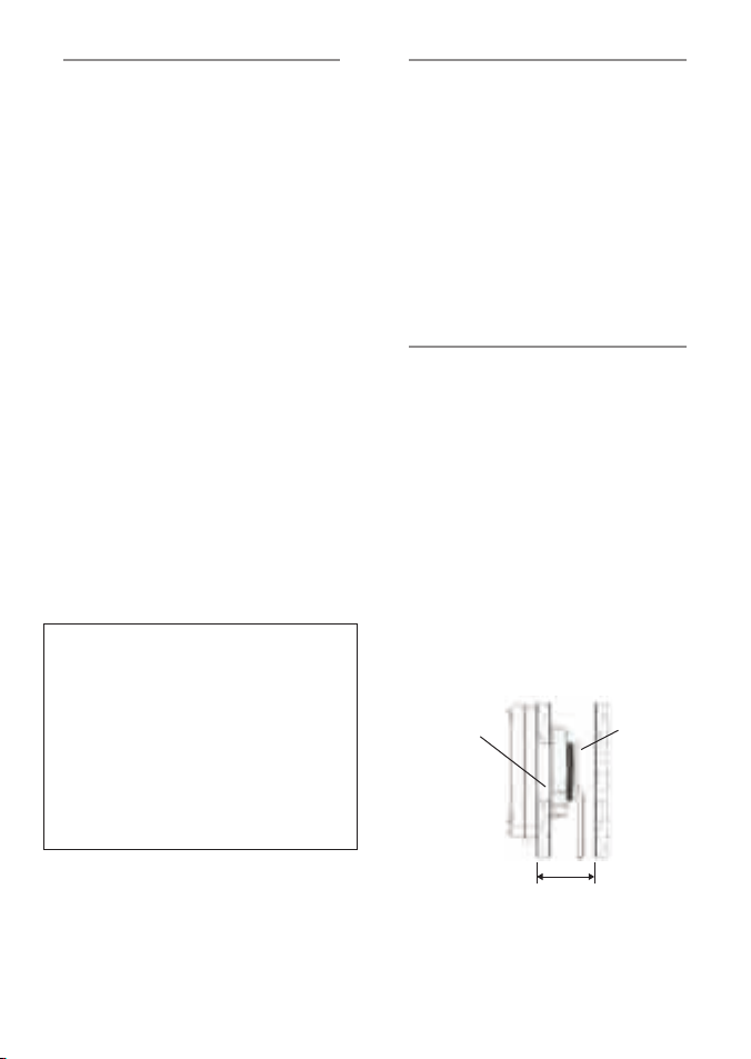
Single fuel tank, twin engines (requi res twin engine kit)
Two fuel
consumption
measurements
Fuel tank
Starboard engine
Port engine
Flow sensor Flow sensor
Twin fuel tanks, twin engines (requires twi n engine kit)
Port fuel tank
Starboard fuel tank
Flow sensor
Starboard enginePort engine
Flow sensor
Two fuel
consumption
measurements
Single fuel tank, single engine
Fuel tank
Flow sensor
Engine
Single fuel
consumption
measurement
4 Installation
There are three options for the FUEL 3100 and
the DIESEL 3200.
A FUEL 3100 uses one sensor to measure fuel
consumption. The DIESEL 3200 uses t wo
sensors to measure fuel consumption, a sensor
in the supply line and a sensor in the return line
(see sec tion 1-1).
To configure the unit for different tank and
engine options, set dUAL and m otor in the
FUEL menu and for twin motors identif y each
engine in the dSL SEn menu by alternately
removing p ower from the flow sensors as
described
in this sec tion.
Note:
Twin fuel tanks connected by an open balance
pipe should be configured as a single fuel tank.
4-1 Tank and engine options
Correct installation is critical to the performance
of the unit. It is vital to read the entire
installation section of this manual, and the
documentation that comes with any optional
other parts, before starting the installation.
For more information, refer to the installation
instruc tions supplied with the sensor, or
consult your Navman dealer.
17
FUEL 3100 / DIESEL 3200 Installation and Ope ration Manual
NAVMA N
Warnings
1. The display unit is waterproof from the
front. Protect the rear from water, otherwise
water might enter the breathing hole and
damage the display unit. The warranty does
not cover damage caused by moisture or
water entering the back of the display unit.
2. Ensure that any holes cut for the
installation will not weaken the boat’s
structure. If in doubt, consult a qualif ied boat
builder.
50 mm (2") minimum
clearance for cables
20 mm (0.75")
maximum thickness
Fixing nutFixing hole
50 mm (2")
Side view of display unit mounting
4-2 The display unit
1 Choose a location for the display unit that:
•
is easily seen and protected from
damage
•
is at least 100 mm (4") from a compass
and at least 500 mm (19.5") from a radio
or radar antenna
•
is away from engines, f luorescent lights,
power inver ters and radio or radar
transmit ters
•
is accessible from the back; a minimum
clearance of 50 mm (2") is required at
the back (see mounting diagram)
•
protects the back of the unit from
moisture and water.
2 The unit must be mounted on a flat panel
less than 20 mm (0.75") thick . Stick the
mounting template in place. Drill a 50 mm
(2") fixing hole through the centre hole
in the template. Note that the template
allows space around the display unit for the
protective cover.
3 Remove the fixing nut from the back of
the display unit. Insert the stud at the back
of the display unit through the mounting
hole. Hand tighten the fixing nut.
4-3 The fuel f low sensor(s)
Install the fuel flow sensor(s) following the
instruc tions in the manual supplied with the
petrol fuel or diesel flow sensor(s). Note the
warning about fuel types in appendix B.
FUEL 3100: Plug the sensor cable into the
FUEL 3100 cable with a white connector and do
up the locking collar. For a twin engine or twin
tank boat, follow the instruc tions in the Fuel
Sensor Instal lation Manual.
DIESEL 3200: Connect the white sensor
cable to the DIESEL 3200. For a twin engine
installation install the white T connector and
then connect the sensor cables to this.
4-4 The speed sensor (optional)
If required, install the optional paddlewheel
speed sensor following the instructions in
the manual supplied with the sensor. Plug the
sensor cable into the FUEL 3100 cable with a
blue connector and do up the locking collar.
If a NavBus or NMEA speed source is used,
connect it to the power/data cable (see nex t
page).
18
FUEL 3100 / DIESEL 3200 Installation and Ope ration Manual
NAVMA N
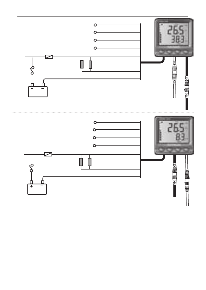
4-5 Power/data c able wiring
Fuse 1 A
12 V DC
Alarm beepers and
lights (optional)
Power to
engine
Engine
ignition
switch
FUEL 310 0
NMEA ground
Notes for both FUEL 3100 and DIESEL 3200:
Use a Navman junction box or any simple wire
to wire connector system to wire the power/data
cable. Tape or cover any unused wires or
connectors to protect them from water and keep
them from shorting together. The unit requires
between 9 and 30 V DC power. To allow the
engine hours counter to function properly the
unit should be powered only when the engine’s
igniton switch is turned on. With twin engines
the unit ideally needs to work when either one
or both engines are running. If acceptable power
is available wire the unit through each ignition
system seperately using an On/On switch.
Alternatively wire it through a seperate switch to
the vessels 12 V power supply. The units must
not be powered from both ignition systems
simultaneously.
If a Navman connector box is not used a 1 A fuse
must be fitted in the power supply (+ ) line.
The instrument’s alarm output is switched to
ground to sound the alarm, 30 V DC and 250 mA
maximum. If the external alarms require more
than 250 mA DC total, fit a relay.
Yellow
White
Orange
Blue
Red
Green
Black
NMEA in (optional)
NMEA out (optional)
NavBus, to other
instruments (optional)
Power/
data cable
Petrol fuel sensor
cable, white plug
Optional paddlewheel
speed sensor, blue plug
Fuse 1 A
12 V DC
Alarm beepers and
lights (optional)
Power to
engine
Engine
ignition
switch
NMEA ground
Yellow
White
Orange
Blue
Red
Green
Black
NMEA in (optional)
NMEA out (optional)
NavBus, to other
instruments (optional)
Power/
data cable
Optional paddlewheel
speed sensor, blue plug
Diesel fuel sensor
cable, white plug
DIESEL 3200
19
FUEL 3100 / DIESEL 3200 Installation and Ope ration Manual
NAVMA N
However, changing the backlight setting in
an instrument in group 0 will not af fect any
other instrument.
To assign the FUEL 3100 or DIESEL 3200 to
a group, set GrouP in the LAmP menu
(see sec tion 3-3).
• If an alarm sounds, mute it by clearing the
alarm on any instrument which can display
that alarm.
• NavBus junction boxes simplify wiring.
For more information, refer to the NavBus
Installatio n and Operation Manu al.
NMEA
NMEA is an industry standard for marine
instrument connec tions. The FUEL 3100 and
DIESEL 3200 :
• Can read speed data (RMC) from a
compatible NMEA GPS instrument (see
section 3-6)
• Transmit PTTKV, VHW, XDR, VLW .
Several Navman instruments can be connected
together to share data, either by using NavBus
or NMEA.
NavBus
NavBus is a Navman proprietary system that is
high speed and allows a wide range of data to
be shared by the instruments.
When instruments are connec ted by NavBus:
• Data from a sensor connected to one
instrument is available to all instrument s.
• If the units, alarms or calibration are
changed in one instrument, then the values
will automatically change in all instruments
of the same t ype.
• Each instrument can be assigned to a group
of instruments by setting a group number
between 0 and 4. Then, if the back light
is changed in an instrument in groups 1,
2, 3 or 4, it will automatically change in
all the other instruments in that group.
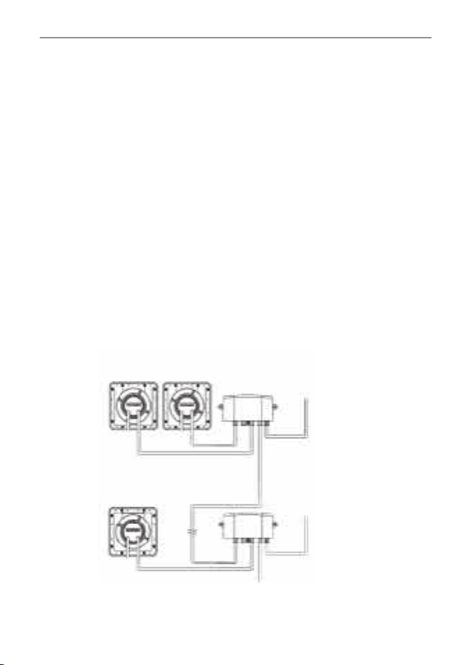
4-6 Systems of severa l instruments
Power/data cables
Junction box
Power and data
connections
Power/data cables
NavBus cable
Group 1
Group 2
A typical NavBus system
Power and data
connections

20
FUEL 3100 / DIESEL 3200 Installation and Ope ration Manual
NAVMA N
To check out the installation:
1 Power on the boat and any other
instruments. Check the instruments work
properly.
2 Enter the setup data (see section 3).
Set d UAL, motor , and InPUt first, then
enter the rest of the setup data.
For boats with t win tanks or twin engines,
remember to enter port and starboard data
separately where required.
3 Fill the fuel tank (s) and set the fuel in the
tank(s) in the FUEL 3100 or DIESEL 3200 (see
section 5).
4 On boats with twin engines, check the
installation of the port and starboard fuel
sensors:
• DIESEL 3200: Star t the port engine. Check
the LED lights under the sensors are
blinking. This indicates the sensors are
operating correc tly. Confirm the fuel flow is
being displayed as port engine fuel usage
on the instrument. (If it is being displayed
as starboard engine fuel usage, swap
over the fuel flow sensor connectors on
the ‘T’ connector.) Repeat the check with
starboard engine.
• FUEL 3100: Star t the port engine. Confirm
the fuel f low is being displayed as port
engine fuel usage on the instrument. If it is
being displayed as starboard engine fuel
usage, reconfigure the set tings (see section
3-3).
5 FUEL 3100 only: Calibrate the fuel sensor(s)
(see sec tion 3-4).
6 If a paddlewheel speed sensor is
connected, calibrate it (see sections 3-8
and 3-9).
7 Take the boat for a trial run and check the
unit is displaying the correct data.
FUEL 3100: Recalibrate the FUEL 3100’s fuel
sensor(s) after the first 100 engine hours (see
section 3-4).
When you add or remove fuel from a tank, you
must enter into the FUEL 3100 or DIESEL 3200
how much fuel you have added or removed.
Otherwise REMAINING, RA NGE and the low
fuel alarm will be meaningless. Twin tanks
connected by an open balance pipe should be
trated as a single fuel tank.
When you add or remove fuel from a tank:
a When you fill a tank
1 Fill the tank.
2 Press until REMAINING is displayed.
3 If the boat has twin tanks, press ENT until
the display shows the name of the tank you
have filled, PORT or STBD.
4 Press and together.
5 If the boat has twin tanks and you are filling
the other tank as well, repeat the ab ove
steps.
Note:
It is often very difficult to refill underfloor
fuel tanks to the same level twice, due to air
pockets. Because of this, owners of boats with
underfloor fuel tanks should:
• Ensure the boat is trimmed to sit at
the same angle in the water each time
procedure a above is followed.
• Mostly use procedure b below when filling
the tank, but use procedure a above about
every tenth fill.
b When you fill or part fill a tank
1 Before adding or removing fuel, press ESC
and ENT together, then press until the
FUEL setup menu is displayed.
2 Press ENT, then press or until the
FUEL data is displayed.
5 When you add or remove fuel
4-7 Testing the inst allation
4-8 Resetting to factor y defaults
To reset to factory defaults:
1 Turn the power off.
2 Hold ENT + while turning on the power
and for at least five seconds af ter.

21
FUEL 3100 / DIESEL 3200 Installation and Ope ration Manual
NAVMA N
6 Troubleshooting
This troubleshooting guide assumes that this
manual has been read and understood.
It is possible in many cases to solve difficulties
without having to send the unit back to the
manufac turer for repair. Please follow this
troubleshooting section before contacting the
nearest Navman dealer.
There are no user ser viceable parts. Specialized
methods and testing equipment are required
to ensure that the unit is reassembled correctly
and is waterproof. Repairs to the unit must only
be carried out by a ser vice centre approved by
Navman NZ Limited. Users who ser vice the unit
themselves will void the warranty.
More information can be found on our website:
www.navman.com
1 Instrument will not turn on:
a Power/data cable is damaged or
disconnected. Perform a visual check.
b Fuse is blown or circuit breaker has tripped.
Replace the fuse or reset the circuit breaker.
c Battery voltage is outside the range 9 to
30 V DC. Check the battery voltage using a
multimeter.
2 The word SIM flashes at bot tom left
corner o f screen, values displayed are
unexpected :
a The instrument is in simulation mode (see
section 2-9).
3 Fuel read ing is wrong or erratic:
a Check for leak s in the fuel line or in the fuel
pickup in the tank.
b Fuel sensor cable is unplugged or damaged.
Perform a visual check. DIESEL 3200: check
the LED light on the underneath of flow
sensor blinks when the engine draws fuel.
c The fuel R EMA INING reading is incorrect.
The fuel tank capacity (SIZE) may be
incorrect, or the fuel RE MAINING setting
may not have been updated after a refill.
See section 5.
d Sensors require calibration (see sec tion 3-4;
diesel sensors do not normally need to be
calibrated).
e The fuel flow sensor may have been
mounted too close to the fuel pump, or
may be subject to excessive vibration. Refer
to the installation instructions supplied
with the fuel sensor.
f The fuel f low sensor damping (dA mP.F)
value is not suitable for the engine. Check
that the value is not set to zero and then try
increasing the value until a steady flow rate
is shown (see section 3-5)
4 Speed reading is wrong or erratic:
a Speed readings require the optional speed
sensor to be installed and setup (see
section 3-6).
3 If the boat has twin tanks, press ENT. Then
press until the display shows the name of
the tank to be filled, PORT or STBD.
4 Write down the number displayed, FUEL,
which is the amount of fuel now in the tank.
5 Add fuel to the tank , writing down how
much you add.
6 Add together the two figures you have
written down, to calculate the amount of
fuel now in the tank. Press ENT. Then press
or hold to change FU EL to the amount
of fuel now in the tank.
7 Press ENT, then press ESC to return to the
main display.
8 If the boat has twin tanks and you are
adding fuel to the other tank as well, repeat
the above steps.
Note:
If you follow procedure b above ever y time you
add fuel, then a small error will accumulate,
because it is hard to measure exac tly how
much fuel you add. To avoid this, about every
ten tankfulls of fuel, fill the tank and follow
procedure a.
c When you remove fuel from a tank
Repeat the steps for procedure b above, but:
i This time subtract the fuel you have
removed from the original amount of fuel
in the tank to calculate the amount of fuel
now in the tank.
ii Press or hold to change FUEL to the
amount of fuel now in the tank.

22
FUEL 3100 / DIESEL 3200 Installation and Ope ration Manual
NAVMA N
b Speed sensor cable is unplugged or
damaged. Perform a visual check.
c Speed calibration is incorrect (see sections
3-8 and 3-9).
d Interference from electrical noise may be
affec ting the measurements. Review the
installation.
5 Low Fuel Alarm sounds when fuel not
low:
a The fuel REMAINING reading is incorrec t.
The fuel tank capacity (SIZE) may be
incorrect, or the fuel RE MAINING setting
may not have been updated after a refill.
See sections 2-6. and 5.
6 The display unit fogs:
a Moist air has entered the breathing tube at
the rear of the unit. Air the boat or run the
instrument with backlight fully on.
b Water has entered the breathing tube.
Return the instrument for ser vicing.
7. Flow indicates no fuel or low fuel
a FUEL 3100 : Check that the fuel cable
connectors are securely plugged in and
the collar is locked in place. The collar must
be locked in place to give a watertight
connection.
b A fuel sensor may be clogged. If so, remove
the sensor from the fuel line and gently
blow through it in the opposite direction to
the fuel f low. A fuel filter between the fuel
sensor and the fuel tank must be installed
as per the fuel installation guide. Failure to
do so will void the warranty.
c Inspect the fuel cable from end to end for
damage such as cuts, breaks, squashed or
trapped sections.
d Check that the fuel filter is clean.
8 Fuel used or remaining seem inaccurate:
a In rough seas, fuel may surge back and
forth through the fuel sensor, resulting in
incorrect readings. Try installing a one-way
valve bet ween the fuel sensor and the fuel
tank.
b The amount of fuel must b e reset after
every refuelling (see sec tion 5 ).
c The fuel tank may not ref ill to the same
capacit y each time due to air pockets. This
is particularly noticable with underfloor
tanks (see section 5).
d Petrol fuel sensors wear out over time and
should be replaced after every 500 0 litres
of fuel.
9 A twin engine installation shows only
one flow rate:
a Check that the number of engines is set to 2
(motor in the FUEL menu, see sec tion 3).
10 There is no reading for fuel economy:
a The boat must be travelling through the
water to generate an economy reading.
b If an optional paddlewheel sensor is fitted,
check that the paddlewheel spins freely.

23
FUEL 3100 / DIESEL 3200 Installation and Ope ration Manual
NAVMA N
Appendix A Specifications
Physical
• Case size 113 mm (4.4") square.
• LCD display 82 mm (3. 2") wide, 61 mm (2.4")
high; twisted nematic.
• LCD digits 30 mm (1.2" ) high on top line,
20 mm (0.8") high on bottom line.
• Four operator keys, laser etched.
• Backlighting for display and keys, amber,
four levels and off.
• Operating temperature 0 to 55°C (32 to
131°F).
• Power/data cable 1.1 m (3.25 ft).
Electrical
• Power supply 10.5 to 16.5 V DC, 30 mA
without backlighting, 80 mA with full
backlighting.
• External alarm : Output is switched to
ground to sound the alarm, 30 V DC and
250 mA maximum.
Fuel
Displays fuel used, fuel remaining, rate of
fuel flow and the fuel economy.
Range 0 to 9999 with resolution of 0.1 unit
for the first 999 units, thereafter resolution
of 1.0 unit.
Log
Displays trip log and total log.
• Range 0 to 9999 miles or nautical miles.
Engine Hours
• Displays 0.0 to 9999.
Engine RPM (DIESEL 3200 only)
• Displays 0 to 9999.
Speed (if optional speed sensor or input is
installed)
• Range 0 to 100 knots (0 to 115 mph).
• Speed resolution of 0.1 unit.
• Adjustable damping for speed and log
gives stable readings in all sea conditions
by averaging the readings. Damping values
available are: 1 (6 sec), 2 (12 sec), 3 (18 sec),
4 (24 sec) or 5 (30 sec).
Calibration
• Fuel sensors can be calibrated (diesel
flow sensors do not normally need to be
calibrated). Speed can also be calibrated if
the optional speed sensor is installed.
Interfaces
• NavBus connection to other Navman
instruments.
• NMEA 0183: Input: RMC.
Outputs: PTTK V, VHW, XDR, VLW
Standards compliance
• EMC compliance
USA (FCC):
Par t 15 Class B.
Europe(CE):
EN50081-1,EN50082-1, EN55024, EN55022,
ISO7637-1.
New Zealand and Australia (C Tick) :
AS-NZS 3548.
• Environment:
IP66 from front when correctly mounted on
the bulkhead.
Power / data cable
Wire Signal
Red Power positive, 12 V DC,
100 mA maximum
Black Ground/Shield (NMEA common)
Green External alarm, switched to
ground, 30 V DC and 250 mA max.
Orange NavBus +
Blue NavBus -
White NMEA output
Yellow NMEA input
24
FUEL 3100 / DIESEL 3200 Installation and Ope ration Manual
NAVMA N
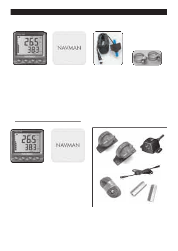
What comes with your FUEL 3100?
Also: Warranty card, mounting template, this manual and the Fuel Sensor Installation Manual.
FUEL 310 0 options:
•
Additional FUEL 3100 display units to repeat the data. These do not require flow sensors.
•
FUEL 3100 twin engine upgrade kit.
B-2 DIESEL 3200
What comes with your DIESEL 3200?
Also: Warranty card, mounting template and
this manual.
DIESEL 3200 options:
•
Additional DIESEL 3200 display
units to repeat the data. These
do not require flow sensors.
•
A second diesel flow sensor
kit, for twin engines.
Appendix B Diesel fuel flow sensor hardware
DIESEL 3200
display unit
Protective cover
Diesel flow sensor kit, with two fuel sensors,
tachometer pickup, cables, two straight
through pipes, Diesel Fuel Flow Sensor
Installation and Operation Manual.
FUEL 3100 display unit Protective cover Fuel flow sensor and
cable,
8 m (26¼ ft)
Two stainless steel
clips
B-1 FUEL 3100
Loading...