


 Loading...
National Instruments NI PCI-6552, NI PXI-6552, PXI-6561, NI PXI-6561, NI PXI-6562 User Manual
...GETTING STARTED GUIDE
NI Digital Waveform
Generator/Analyzer
This document explains how to install, configure, test, and set up a National Instruments digital waveform generator/analyzer. This document applies specifically to the following devices:
•NI PXI/PCI-6541/6542 (NI 654X)
•NI PXI/PCI-6551/6552 (NI 655X)
•NI PXI-6561/6562 (NI 656X)
For more information about features and programming, refer to the
NI Digital Waveform Generator/Analyzer Help at Start»Programs»
National Instruments»NI-HSDIO»Documentation» NI Digital Waveform Generator/Analyzer Help.
Refer to the specifications document that ships with your device for detailed specifications.
For free downloads of the most current versions of product documentation and example programs, visit ni.com/instruments.
Contents |
|
|
Conventions ............................................................................................... |
2 |
|
1. |
Verifying the System Components ........................................................ |
4 |
|
Minimum System Requirements ....................................................... |
4 |
|
Recommended System....................................................................... |
4 |
2. |
Unpacking.............................................................................................. |
5 |
3. |
Verifying the Kit Contents..................................................................... |
6 |
|
Documentation................................................................................... |
6 |
|
EMI Gasket (NI PXI-655X Only)...................................................... |
6 |
4. |
Installing the Software ........................................................................... |
6 |
|
Choose and Install Your ADE ........................................................... |
6 |
|
Install NI-HSDIO............................................................................... |
7 |
|
(Optional) Install the NI Digital Waveform Editor ........................... |
7 |
January 2005
373308E-01
5. |
Installing the Hardware.......................................................................... |
8 |
|
Installing a PXI Module..................................................................... |
8 |
|
Installing a PCI Device ...................................................................... |
10 |
6. |
Configuring and Testing in MAX.......................................................... |
11 |
|
Using the Test Panel to Generate and Acquire Data ......................... |
12 |
7. Connecting Signals ................................................................................ |
14 |
|
|
Connecting Cables and Accessories .................................................. |
14 |
|
Wiring for Common Measurements .................................................. |
16 |
8. |
Programming the Digital Waveform Generator/Analyzer..................... |
18 |
|
NI-HSDIO Instrument Driver............................................................ |
18 |
|
NI-HSDIO Examples......................................................................... |
18 |
Appendix A: Device Front Panels ............................................................. |
18 |
|
Appendix B: Troubleshooting ................................................................... |
26 |
|
Technical Support Resources..................................................................... |
28 |
|
Conventions
The following conventions are used in this guide:
<> |
Angle brackets that contain numbers separated by |
||
|
|
|
an ellipsis represent a range of values associated |
|
|
|
with a bit or signal name—for example, |
|
|
|
DIO <3..0>. |
» |
|
|
The » symbol leads you through nested menu items |
|
|
|
and dialog box options to a final action. The |
|
|
|
sequence File»Page Setup»Options directs you to |
|
|
|
pull down the File menu, select the Page Setup |
|
|
|
item, and select Options from the last dialog box. |
|
|
|
This icon denotes a tip, which alerts you to advisory |
|
|
|
information. |
|
|
|
This icon denotes a note, which alerts you to |
|
|
|
important information. |
|
|
|
This icon denotes a caution, which advises you of |
|
|
|
precautions to take to avoid injury, data loss, or a |
|
|
|
system crash. When this symbol is marked on the |
|
|
|
product, refer to the Read Me First: Safety and |
|
|
|
Radio-Frequency Interference document that |
|
|
|
shipped with your device for precautions to take. |
bold |
Bold text denotes items that you must select or click |
||
|
|
|
in the software, such as menu items and dialog box |
|
|
|
options. Bold text also denotes parameter names. |
NI Digital Waveform Generator/Analyzer Guide |
2 |
ni.com |

CompactPCI |
CompactPCI refers to the core specification defined |
|
by the PCI Industrial Computer Manufacturers |
|
Group (PICMG). |
italic |
Italic text denotes variables, emphasis, or a cross |
|
reference. This font also denotes text that is a |
|
placeholder for a word or value that you must |
|
supply. |
monospace |
Text in this font denotes text or characters that you |
|
should enter from the keyboard, sections of code, |
|
programming examples, and syntax examples. This |
|
font is also used for the proper names of disk drives, |
|
paths, directories, programs, subprograms, |
|
subroutines, device names, functions, operations, |
|
variables, filenames, and extensions. |
monospace bold |
Bold text in this font denotes the messages and |
|
responses that the computer automatically prints to |
|
the screen. This font also emphasizes lines of code |
|
that are different from the other examples. |
monospace italic |
Italic text in this font denotes text that is a |
|
placeholder for a word or value that you must |
|
supply. |
PCI |
Peripheral Component Interconnect (PCI) is a |
|
high-performance expansion bus architecture |
|
originally developed by Intel to replace ISA |
|
and EISA. |
PXI |
PCI eXtensions for Instrumentation (PXI) is a |
|
rugged, open system for modular instrumentation |
|
based on CompactPCI, with special mechanical, |
|
electrical, and software features. |
1. Verifying the System Components
This section specifies the minimum system requirements and recommended system for NI-HSDIO and your digital waveform generator/analyzer.
Minimum System Requirements
The minimum system requirements include the following components and tools:
•Pentium 200 MHz or equivalent processor
•64 MB RAM
•A PXI chassis and controller or desktop computer
© National Instruments Corporation |
3 |
NI Digital Waveform Generator/Analyzer Guide |
•1/8 in. flathead screwdriver
•Number 1 Phillips screwdriver
•Microsoft Internet Explorer 5.5 or later
•Measurement & Automation Explorer (MAX) 3.1 or later
•A screen resolution of 800 × 600 with 256 colors (required for the NI Script Editor)
•The appropriate cable for your device, as shown in the following table:
Table 1. NI Digital Waveform Generator/Analyzer Cables
Device |
Cable |
Cable Part Number |
|
|
|
|
|
|
NI 654X |
NI SHC68-C68-D2 |
188142-01 |
|
|
|
NI 655X |
NI SHC68-C68-D2 |
188142-01 |
|
|
|
NI 656X |
NI SHB12X-B12X |
192344-01 |
|
|
|
•NI EMC Filler Panel Kit, available from NI (part number 778700-01)
Recommended System
The recommended system requirements include the following components and tools:
•Pentium III/Celeron 600 MHz or equivalent processor
•256 MB RAM
•A PXI chassis and controller or desktop computer
•1/8 in. flathead screwdriver
•Number 1 Phillips screwdriver
•Microsoft Internet Explorer 5.5 or later
•Measurement & Automation Explorer (MAX) 3.1 or later
•A screen resolution of 800 × 600 with 256 colors (required for the NI Script Editor)
•The appropriate cable for your device, listed in Table 1.
•A compatible connectivity accessory for your NI digital waveform generator/analyzer, listed in the following table:
Table 2. NI Digital Waveform Generator/Analyzer Accessories
Accessory |
Supported Devices |
|
|
|
|
NI CB-2162 |
NI 654X, NI 655X |
|
|
NI SMB-2163 |
NI 654X, NI 655X |
|
|
NI Digital Waveform Generator/Analyzer Guide |
4 |
ni.com |

•Windows 2000/NT/XP, with all available critical updates and service packs
•One of the following application development environments (ADEs):
–LabVIEW 7.0 or later (LabVIEW 7.1 or later is required to use the NI-HSDIO Express VIs)
–LabVIEW Real-Time Module 7.1
–LabWindows™/CVI™ 6.0 or later
–Microsoft Visual C++ (MSVC) 6.0 or later
2. Unpacking
The NI digital waveform generator/analyzer ships in an antistatic package to prevent electrostatic discharge (ESD). ESD can damage several components on the device.
Caution Never touch the exposed pins of connectors.
To avoid ESD damage in handling the device, take the following precautions:
•Ground yourself with a grounding strap or by touching a grounded object.
•Touch the antistatic package to a metal part of your computer chassis before removing the device from the package.
Remove the device from the package and inspect it for loose components or any other signs of damage. Notify NI if the device appears damaged in any way. Do not install a damaged device in your computer or chassis.
Store the device in the antistatic package when the device is not in use.
3. Verifying the Kit Contents
Verify that the kit contains the following items:
DVD-sized case, which contains the following items:
–NI-HSDIO (High-Speed Digital I/O) instrument driver software CDs, which include the NI Digital Waveform Generator/Analyzer Help
–NI Digital Waveform Generator/Analyzer Getting Started Guide
NI digital waveform generator/analyzer
Mounting screw (PCI devices only)
© National Instruments Corporation |
5 |
NI Digital Waveform Generator/Analyzer Guide |

Other documentation included with the digital waveform generator/analyzer and driver software. Refer to the Documentation section for a list of the documentation you may have.
Documentation
The NI digital waveform generator/analyzer kit may also include the following documents:
•NI digital waveform generator/analyzer specifications—This printed document provides specifications for your device.
•Read Me First: Safety and Radio-Frequency Interference
•Maintain Forced-Air Cooling Note to Users
•Retrofitting Your PXI Module Note to Users
EMI Gasket (NI PXI-655X Only)
The NI PXI-655X kit also includes an EMI gasket and documentation that describes under what conditions you should install the gasket. Refer to step 5. Installing the Hardware for more information about the gasket.
4. Installing the Software
This section describes the software installation process for the NI digital waveform generator/analyzer.
Choose and Install Your ADE
You can create applications for your digital waveform generator/analyzer using LabVIEW 7.0 or later, LabWindows/CVI 6.0 or later, or Microsoft Visual C++ 5.0 or later.
LabVIEW features interactive graphics, a state-of-the-art interface, and a powerful graphical programming language. LabWindows/CVI is a complete ANSI C ADE that features an interactive user interface, code generation tools, and the LabWindows/CVI Data Acquisition and Easy I/O libraries. Using LabVIEW or LabWindows/CVI can greatly reduce your application development time.
If you have not already installed the ADE, follow the instructions in the product documentation to install your ADE now.
NI Digital Waveform Generator/Analyzer Guide |
6 |
ni.com |

Install NI-HSDIO
NI-HSDIO features a set of operations and attributes that allow you to programmatically configure and control the digital waveform generator/analyzer. To install NI-HSDIO, complete the following steps:
1.Insert the first CD of the NI-HSDIO CD set. The NI-HSDIO installer should open automatically. If not, select Start»Run, and enter x:\setup.exe, where x is the letter of the CD drive.
2.Follow the instructions in the installation prompts. For troubleshooting and operating system-specific instructions, refer to the Hardware Installation Wizard at ni.com/support/install.
3.When the installer completes, a dialog box appears that asks if you want to restart, shut down, or exit. Select Restart.
4.If you are using a system running the LabVIEW Real-Time Module, download NI-HSDIO to the target using MAX. Refer to the
Measurement & Automation Explorer Remote Systems Help by selecting
Help»Help Topics»Remote Systems in MAX.
NI Script Editor
The NI Script Editor is included on the NI-HSDIO CD and is installed when you install the driver. The NI Script Editor provides an intuitive interface to help you develop linking and looping pattern generation operations.
NI Script Editor Help contains more information about the NI Script Editor. You can access NI Script Editor Help by launching the NI Script Editor and selecting Help»NI Script Editor Help from the toolbar.
(Optional) Install the NI Digital Waveform Editor
The NI Digital Waveform Editor (DWE) is included with the higher-memory versions of NI digital waveform generator/analyzers and also can be purchased separately at ni.com. The NI DWE allows you to easily import data from popular third-party EDA programs, create your own waveforms, edit these waveforms, and view acquired waveforms.
If you are using the NI DWE, install it after you install NI-HSDIO.
5. Installing the Hardware
To install your NI digital waveform generator/analyzer, follow the instructions in the section that describes your hardware platform.
When installing your hardware, follow the instructions in this section to ensure that your device can cool itself effectively. If the device temperature rises above the optimal operating temperature range, the device disables itself, and MAX or NI-HSDIO notifies you with an error message. For more
© National Instruments Corporation |
7 |
NI Digital Waveform Generator/Analyzer Guide |

information on re-enabling your device, refer to the I Received a Thermal Shutdown Error section in Appendix B: Troubleshooting.
Installing a PXI Module
To install the module, refer to Figure 1 and complete the following steps:
|
1 |
|
4 |
NI |
PXI- |
3 |
|
1042 |
|
|
|
|
2 |
|
1 |
PXI Chassis |
3 |
Captive Screw |
2 |
Ejector Handle |
4 |
NI PXI Device |
|
|
|
|
Figure 1. PXI Installation
1.Power down the chassis before installing the module.
2.If the chassis has multiple fan speed settings, ensure that the fans are set to the highest setting. Do not set the fan speed to low or turn the fan off.
3.Position the chassis so that you allow plenty of space between the chassis fan intake and exhaust vents. Blocking the fans affects the air flow needed for cooling. For more information, refer to the chassis documentation.
4.If you need to use an EMI gasket to reduce high-frequency emissions, install it now. Refer to the Retrofitting Your PXI Module Note to Users for gasket installation instructions.
5.Remove the packaging material on the PXI connector and on the screws.
6.Ensure that the ejector handle is in the unlatched (downward) position, as shown in Figure 1.
NI Digital Waveform Generator/Analyzer Guide |
8 |
ni.com |

7.Holding the module by the ejector handle, slide it into an empty slot, ensuring that the base card (on the left when looking at the front of the module) engages with the card guides in the chassis.
8.Slide the module completely into the chassis and latch by pulling up on the ejector handle.
9.Tighten the captive screws at the top and bottom of the module front panel.
10.Before operating the module, install all chassis covers and filler panels. Missing filler panels disrupt the necessary air circulation in the chassis.
Note NI recommends that you install slot blockers between modules to maximize air flow. NI recommends using the PXI Chassis Slot Blocker Kit, part number 778678-01, available for purchase at ni.com.
NI PXI modules are sensitive instruments that should be handled carefully. Do not expose the module to temperatures or humidity beyond the rated maximums. Keep the module free of dust by cleaning with compressed air only. Do not clean the module with any solvents or liquids. For more information about module cooling, refer to the guidelines in the Maintain Forced-Air Cooling Note to Users included with your NI digital waveform generator/analyzer.
Maintaining PXI Systems
Clean the fan filters on the chassis regularly to prevent air circulation path blockage. Cleaning frequency depends on the amount of use and the operating environment. For specific information about cleaning procedures, and other recommended maintenance, refer to the module specifications and the chassis user documentation.
Uninstalling PXI Modules
When removing PXI modules from the chassis, first power down the chassis. Then ensure that you are grounded with a grounding strap or are touching a grounded metal surface. To avoid ESD, do not touch the exposed pins of the PXI connector or any exposed circuitry on the module. When not in use, PXI modules should be stored in the original antistatic packaging to avoid damage.
Caution During operation the metal surfaces of PXI modules may become hot. Be careful when removing the module from the chassis or when moving it to a different peripheral slot. When removing the module, hold it by the ejector handle and front panel only.
© National Instruments Corporation |
9 |
NI Digital Waveform Generator/Analyzer Guide |
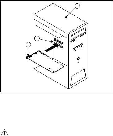
Installing a PCI Device
To install your PCI device, complete the following steps:
1.Power off and unplug the PC.
2.If the PC has multiple fan speed settings, ensure that the fans are set to the highest setting.
3.Remove the PC cover.
4.Insert the device into an open PCI slot, as shown in Figure 2.
3
2
1
1 NI PCI Device |
2 PCI Slot |
3 Personal Computer |
|
|
|
Figure 2. PCI Installation
NI recommends either leaving the slot adjacent to the fan side of the device empty or using lower-profile devices in the slot adjacent to the fan side.
5. Secure the device with the screw provided in the kit.
Caution It is important to completely screw the device into the PCI slot, both for mechanical stability and for creating a solid ground connection, which reduces signal noise. Some computer manufacturers use a plastic securing lever to secure PCI devices; such a lever is unacceptable and must be removed, or you must use
NI Digital Waveform Generator/Analyzer Guide |
10 |
ni.com |
Loading...