


MXITM
MXI-4 Series User Manual
MXI-4 Multi-System Extension Interface for PCI, CompactPCI, and PXI Bus Computers
PCI-8331
PXI-8331
PCI-8336
PXI-8336
MXI-4 Series User Manual
December 2003 Edition
Part Number 370840A-01
Worldwide Technical Support and Product Information
ni.com
National Instruments Corporate Headquarters
11500 North Mopac Expressway Austin, Texas 78759-3504 USA Tel: 512 683 0100
Worldwide Offices
Australia 1800 300 800, Austria 43 0 662 45 79 90 0, Belgium 32 0 2 757 00 20, Brazil 55 11 3262 3599, Canada (Calgary) 403 274 9391, Canada (Ottawa) 613 233 5949, Canada (Québec) 450 510 3055, Canada (Toronto) 905 785 0085, Canada (Vancouver) 514 685 7530, China 86 21 6555 7838,
Czech Republic 420 224 235 774, Denmark 45 45 76 26 00, Finland 385 0 9 725 725 11,
France 33 0 1 48 14 24 24, Germany 49 0 89 741 31 30, Greece 30 2 10 42 96 427, India 91 80 51190000, Israel 972 0 3 6393737, Italy 39 02 413091, Japan 81 3 5472 2970, Korea 82 02 3451 3400,
Malaysia 603 9131 0918, Mexico 001 800 010 0793, Netherlands 31 0 348 433 466,
New Zealand 0800 553 322, Norway 47 0 66 90 76 60, Poland 48 22 3390150, Portugal 351 210 311 210, Russia 7 095 783 68 51, Singapore 65 6226 5886, Slovenia 386 3 425 4200, South Africa 27 0 11 805 8197, Spain 34 91 640 0085, Sweden 46 0 8 587 895 00, Switzerland 41 56 200 51 51, Taiwan 886 2 2528 7227, Thailand 662 992 7519, United Kingdom 44 0 1635 523545
For further support information, refer to the Technical Support and Professional Services appendix. To comment on the documentation, send email to techpubs@ni.com.
© 2003 National Instruments Corporation. All rights reserved.

Important Information
Warranty
The PXI-PCI 8331 and 8336 hardware is warranted against defects in materials and workmanship for a period of one year from the date of shipment, as evidenced by receipts or other documentation. National Instruments will, at its option, repair or replace equipment that proves to be defective during the warranty period. This warranty includes parts and labor.
The media on which you receive National Instruments software are warranted not to fail to execute programming instructions, due to defects in materials and workmanship, for a period of 90 days from date of shipment, as evidenced by receipts or other documentation. National Instruments will, at its option, repair or replace software media that do not execute programming instructions if National Instruments receives notice of such defects during the warranty period. National Instruments does not warrant that the operation of the software shall be uninterrupted or error free.
A Return Material Authorization (RMA) number must be obtained from the factory and clearly marked on the outside of the package before any equipment will be accepted for warranty work. National Instruments will pay the shipping costs of returning to the owner parts which are covered by warranty.
National Instruments believes that the information in this document is accurate. The document has been carefully reviewed for technical accuracy. In the event that technical or typographical errors exist, National Instruments reserves the right to make changes to subsequent editions of this document without prior notice to holders of this edition. The reader should consult National Instruments if errors are suspected. In no event shall National Instruments be liable for any damages arising out of or related to this document or the information contained in it.
EXCEPT AS SPECIFIED HEREIN, NATIONAL INSTRUMENTS MAKES NO WARRANTIES, EXPRESS OR IMPLIED, AND SPECIFICALLY DISCLAIMS ANY WARRANTY OF MERCHANTABILITY OR FITNESS FOR A PARTICULAR PURPOSE. CUSTOMER’S RIGHT TO RECOVER DAMAGES CAUSED BY FAULT OR NEGLIGENCE ON THE PART OF
NATIONAL INSTRUMENTS SHALL BE LIMITED TO THE AMOUNT THERETOFORE PAID BY THE CUSTOMER. NATIONAL INSTRUMENTS WILL NOT BE LIABLE FOR
DAMAGES RESULTING FROM LOSS OF DATA, PROFITS, USE OF PRODUCTS, OR INCIDENTAL OR CONSEQUENTIAL DAMAGES, EVEN IF ADVISED OF THE POSSIBILITY
THEREOF. This limitation of the liability of National Instruments will apply regardless of the form of action, whether in contract or tort, including negligence. Any action against National Instruments must be brought within one year after the cause of action accrues. National Instruments shall not be liable for any delay in performance due to causes beyond its reasonable control. The warranty provided herein does not cover damages, defects, malfunctions, or service failures caused by owner’s failure to follow the National Instruments installation, operation, or maintenance instructions; owner’s modification of the product; owner’s abuse, misuse, or negligent acts; and power failure or surges, fire, flood, accident, actions of third parties, or other events outside reasonable control.
Copyright
Under the copyright laws, this publication may not be reproduced or transmitted in any form, electronic or mechanical, including photocopying, recording, storing in an information retrieval system, or translating, in whole or in part, without the prior written consent of National Instruments Corporation.
Trademarks
LabVIEW™, MXI™, National Instruments™, NI™, ni.com™, and NI-VISA™ are trademarks of National Instruments Corporation.
Product and company names mentioned herein are trademarks or trade names of their respective companies.
Patents
For patents covering National Instruments products, refer to the appropriate location: Help»Patents in your software, the patents.txt file on your CD, or ni.com/patents.
WARNING REGARDING USE OF NATIONAL INSTRUMENTS PRODUCTS
(1)NATIONAL INSTRUMENTS PRODUCTS ARE NOT DESIGNED WITH COMPONENTS AND TESTING FOR A LEVEL OF RELIABILITY SUITABLE FOR USE IN OR IN CONNECTION WITH SURGICAL IMPLANTS OR AS CRITICAL COMPONENTS IN ANY LIFE SUPPORT SYSTEMS WHOSE FAILURE TO PERFORM CAN REASONABLY BE EXPECTED TO CAUSE SIGNIFICANT INJURY TO A HUMAN.
(2)IN ANY APPLICATION, INCLUDING THE ABOVE, RELIABILITY OF OPERATION OF THE SOFTWARE PRODUCTS CAN BE IMPAIRED BY ADVERSE FACTORS, INCLUDING BUT NOT LIMITED TO FLUCTUATIONS IN ELECTRICAL POWER SUPPLY, COMPUTER HARDWARE MALFUNCTIONS, COMPUTER OPERATING SYSTEM SOFTWARE FITNESS, FITNESS OF COMPILERS AND DEVELOPMENT SOFTWARE USED TO DEVELOP AN APPLICATION, INSTALLATION ERRORS, SOFTWARE AND HARDWARE COMPATIBILITY PROBLEMS, MALFUNCTIONS OR FAILURES OF ELECTRONIC MONITORING OR CONTROL DEVICES, TRANSIENT FAILURES OF ELECTRONIC SYSTEMS (HARDWARE AND/OR SOFTWARE), UNANTICIPATED USES OR MISUSES, OR ERRORS ON THE PART OF THE USER OR APPLICATIONS DESIGNER (ADVERSE FACTORS SUCH AS THESE ARE HEREAFTER COLLECTIVELY TERMED “SYSTEM FAILURES”). ANY APPLICATION WHERE A SYSTEM FAILURE WOULD CREATE A RISK OF HARM TO PROPERTY OR PERSONS (INCLUDING THE RISK OF BODILY INJURY AND DEATH) SHOULD NOT BE RELIANT SOLELY UPON ONE FORM OF ELECTRONIC SYSTEM DUE TO THE RISK OF SYSTEM FAILURE. TO AVOID DAMAGE, INJURY, OR DEATH, THE USER OR APPLICATION DESIGNER MUST TAKE REASONABLY PRUDENT STEPS TO PROTECT AGAINST SYSTEM FAILURES, INCLUDING BUT NOT LIMITED TO BACK-UP OR SHUT DOWN MECHANISMS. BECAUSE EACH END-USER SYSTEM IS CUSTOMIZED AND DIFFERS FROM NATIONAL INSTRUMENTS' TESTING PLATFORMS AND BECAUSE A USER OR APPLICATION DESIGNER MAY USE NATIONAL INSTRUMENTS PRODUCTS IN COMBINATION WITH OTHER PRODUCTS IN A MANNER NOT EVALUATED OR CONTEMPLATED BY NATIONAL INSTRUMENTS, THE USER OR APPLICATION DESIGNER IS ULTIMATELY RESPONSIBLE FOR VERIFYING AND VALIDATING THE SUITABILITY OF NATIONAL INSTRUMENTS PRODUCTS WHENEVER NATIONAL INSTRUMENTS PRODUCTS ARE INCORPORATED IN A SYSTEM OR APPLICATION, INCLUDING, WITHOUT LIMITATION, THE APPROPRIATE DESIGN, PROCESS AND SAFETY LEVEL OF SUCH SYSTEM OR APPLICATION.

Compliance
Compliance with FCC/Canada Radio Frequency Interference Regulations
Determining FCC Class
The Federal Communications Commission (FCC) has rules to protect wireless communications from interference. The FCC places digital electronics into two classes. These classes are known as Class A (for use in industrial-commercial locations only) or Class B (for use in residential or commercial locations). All National Instruments (NI) products are FCC Class A products.
Depending on where it is operated, this Class A product could be subject to restrictions in the FCC rules. (In Canada, the Department of Communications (DOC), of Industry Canada, regulates wireless interference in much the same way.) Digital electronics emit weak signals during normal operation that can affect radio, television, or other wireless products.
All Class A products display a simple warning statement of one paragraph in length regarding interference and undesired operation. The FCC rules have restrictions regarding the locations where FCC Class A products can be operated.
Consult the FCC Web site at www.fcc.gov for more information.
FCC/DOC Warnings
This equipment generates and uses radio frequency energy and, if not installed and used in strict accordance with the instructions in this manual and the CE marking Declaration of Conformity*, may cause interference to radio and television reception. Classification requirements are the same for the Federal Communications Commission (FCC) and the Canadian Department of Communications (DOC).
Changes or modifications not expressly approved by NI could void the user’s authority to operate the equipment under the FCC Rules.
Class A
Federal Communications Commission
This equipment has been tested and found to comply with the limits for a Class A digital device, pursuant to part 15 of the FCC Rules. These limits are designed to provide reasonable protection against harmful interference when the equipment is operated in a commercial environment. This equipment generates, uses, and can radiate radio frequency energy and, if not installed and used in accordance with the instruction manual, may cause harmful interference to radio communications. Operation of this equipment in a residential area is likely to cause harmful interference in which case the user is required to correct the interference at their own expense.
Canadian Department of Communications
This Class A digital apparatus meets all requirements of the Canadian Interference-Causing Equipment Regulations. Cet appareil numérique de la classe A respecte toutes les exigences du Règlement sur le matériel brouilleur du Canada.
Compliance with EU Directives
Users in the European Union (EU) should refer to the Declaration of Conformity (DoC) for information* pertaining to the CE marking. Refer to the Declaration of Conformity (DoC) for this product for any additional regulatory compliance information. To obtain the DoC for this product, visit ni.com/hardref.nsf, search by model number or product line, and click the appropriate link in the Certification column.
*The CE marking Declaration of Conformity contains important supplementary information and instructions for the user or installer.

Contents
About This Manual
Conventions ................................................................................................................... |
vii |
Related Documentation.................................................................................................. |
viii |
Chapter 1
Introduction
About the MXI-4 Series................................................................................................. |
1-1 |
Description and Features ................................................................................. |
1-1 |
Basic MXI-4 Systems...................................................................................... |
1-2 |
Larger MXI-4 Systems .................................................................................... |
1-3 |
What You Need to Get Started ...................................................................................... |
1-5 |
Unpacking ...................................................................................................................... |
1-5 |
Chapter 2
Hardware and Software Installation
Software Installation ...................................................................................................... |
2-1 |
Hardware Installation..................................................................................................... |
2-2 |
Installing a PCI MXI-4 Card ........................................................................... |
2-2 |
Installing a PXI MXI-4 Card........................................................................... |
2-3 |
Cabling ............................................................................................................ |
2-5 |
Powering Up the MXI-4 System ..................................................................... |
2-6 |
Powering Down the MXI-4 System ................................................................ |
2-6 |
Chapter 3
Hardware and Software Overview
Hardware Overview....................................................................................................... |
3-1 |
|
Functional Overview ....................................................................................... |
3-1 |
|
Functional Unit Descriptions........................................................................... |
3-2 |
|
|
National Instruments MXI-4 FPGA.................................................. |
3-2 |
|
Parallel-to-Serial Converter .............................................................. |
3-2 |
|
Serial-to-Parallel Converter .............................................................. |
3-2 |
|
Serial Connector/Fiber Optic Transceiver ........................................ |
3-2 |
MXI-4 |
Cable Options ...................................................................................... |
3-3 |
Software Configuration.................................................................................................. |
3-3 |
|
MXI-4 |
Retransmit Count................................................................................. |
3-3 |
MXI-4 |
Linked Chassis Status.......................................................................... |
3-6 |
© National Instruments Corporation |
v |
MXI-4 Series User Manual |
Contents
Appendix A
Specifications
Appendix B
Common Questions
Appendix C
Technical Support and Professional Services
Glossary
Index
MXI-4 Series User Manual |
vi |
ni.com |
About This Manual
This manual describes the features, functions, and operation of the MXI-4 series of products. The four products in this series are the PCI-8331, PXI-8331, PCI-8336, and PXI-8336. The PXI-PCI 8331 and 8336 incorporate MXI-4 technology, which couples two physically separate PCI, CompactPCI, or PXI buses with a data link capable of 1.5 Gbit/s serial data rates.
Conventions
|
The following conventions appear in this manual: |
|
|
This icon denotes a note, which alerts you to important information. |
|
|
This icon denotes a caution, which advises you of precautions to take to |
|
|
avoid injury, data loss, or a system crash. |
|
bold |
Bold text denotes items that you must select or click in the software, such |
|
|
as menu items and dialog box options. Bold text also denotes parameter |
|
|
names. |
|
italic |
Italic text denotes variables, emphasis, a cross reference, or an introduction |
|
|
to a key concept. This font also denotes text that is a placeholder for a word |
|
|
or value that you must supply. |
|
monospace |
Text in this font denotes text or characters that you should enter from the |
|
|
keyboard, sections of code, programming examples, and syntax examples. |
|
|
This font is also used for the proper names of disk drives, paths, directories, |
|
|
programs, subprograms, subroutines, device names, functions, operations, |
|
|
variables, filenames and extensions, and code excerpts. |
|
MXI-4 card |
MXI-4 card refers to any of the following cards, unless otherwise noted: |
|
|
PCI-8331, PXI-8331, PCI-8336, and PXI-8336. |
|
MXI-4 dyad |
MXI-4 dyad refers to any of the following 4 pairs of MXI-4 cards: |
|
|
• |
PCI-8331 and PXI-8331 |
|
• |
PCI-8336 and PXI-8336 |
|
• |
PXI-8331 and PXI-8331 |
|
• |
PXI-8336 and PXI-8336 |
© National Instruments Corporation |
vii |
MXI-4 Series User Manual |
About This Manual
Note In this manual, whenever a PXI chassis is referenced, a CompactPCI chassis could be used instead.
Related Documentation
The following documents contain information that you might find helpful as you read this manual:
•Set Up Your MXI-4 System
•Your computer or chassis documentation
•PXI Hardware Specification, Revision 2.1
•PXI Software Specification, Revision 2.1
•PCI Specification, Revision 2.2
•PCI-PCI Bridge Architecture Specification, Revision 1.0
•PICMG CompactPCI 2.0 R2.1 specification
MXI-4 Series User Manual |
viii |
ni.com |

1
Introduction
This chapter describes the MXI-4 series of products, lists what you need to get started, and explains how to unpack and set up your hardware.
The four products in this series are the PCI-8331, PXI-8331, PCI-8336, and PXI-8336. For the remainder of this manual the term MXI-4 card will refer to any of the products in the MXI-4 series.
MXI-4 cards must always be installed as either a pair of PXI cards or as a PCI card and a PXI card. The term MXI-4 dyad will refer to one of the four allowable pairings of MXI-4 cards which are described in the Conventions section of the About This Manual.
About the MXI-4 Series
Description and Features
A MXI-4 dyad is a PCI master/slave implementing the PCI-PCI bridge register set. It couples two physically separate buses with either a copper or fiber-optic data link capable of 1.5 Gbit/s serial data rates. With the MXI-4 dyad, you can do the following:
•Control a PXI/CompactPCI backplane with a PCI based PC
•Control a PXI/CompactPCI backplane with another PXI/CompactPCI system
•Increase the available number CompactPCI or PXI slots for your application
•Physically separate the measurement or automation system from a host PC
•Combine PCI, CompactPCI, and PXI devices in the same system
© National Instruments Corporation |
1-1 |
MXI-4 Series User Manual |
Chapter 1 |
Introduction |
Basic MXI-4 Systems
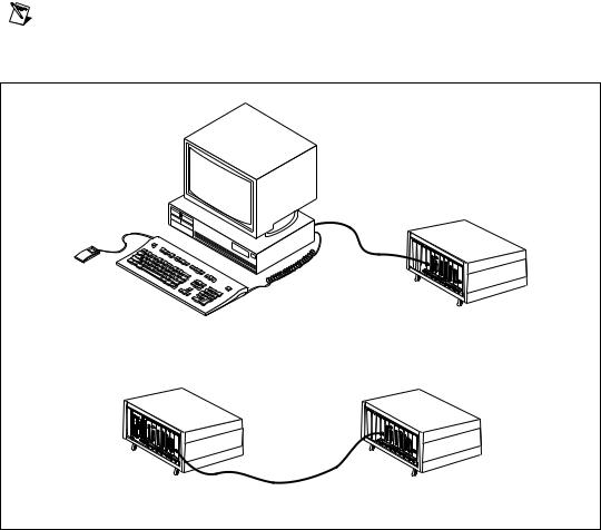
MXI-4 cards are used in two basic configurations, both of which are shown in Figure 1-1:
•A PCI MXI-4 in a PC, connected to a PXI MXI-4 in the controller slot of a PXI/CompactPCI chassis.
•A PXI MXI-4 in a non-controller slot of a PXI/CompactPCI chassis with an embedded controller, connected to a PXI MXI-4 in the controller slot of another PXI/CompactPCI chassis.
Note The PXI MXI-4 is capable of automatically detecting whether it is in a controller or non-controller slot and configuring itself accordingly.
PC to PXI/CompactPCI
PXI/CompactPCI to PXI/CompactPCI
Figure 1-1. Basic MXI-4 Configurations
MXI-4 Series User Manual |
1-2 |
ni.com |
Chapter 1 |
Introduction |
Larger MXI-4 Systems
Using multiple MXI-4 dyads, large PCI/PXI/CompactPCI systems can be created. The PCI specification makes provisions for up to 255 bus segments to simultaneously exist in a PCI hierarchy and MXI-4 hardware provides everything needed to support those provisions.
Notes Keep in mind that some chassis and PCs have more than one PCI bus segment.
The host configuration software (BIOS and OS) and device drivers must support the number of bus segments and PCI devices that you intend to use.
Figure 1-2 shows how MXI-4 cards can be used to connect multiple expansion chassis to a PC in both a star and daisy chain topology. The PC that is shown at the root of the PCI hierarchy in this example could instead be a PXI/CompactPCI chassis with an embedded controller in its controller slot. The star topology will give higher performance than the daisy chain because it minimizes the number of MXI-4 dyads between the expansion cards and the PC.
© National Instruments Corporation |
1-3 |
MXI-4 Series User Manual |

Chapter 1 |
Introduction |
|
Daisy-Chain Configuration |
|
Star Configuration |
Figure 1-2. Star and Daisy Chain MXI-4 Configurations
Note Adding PCI bridges, such as MXI-4, to a system can create a slight decrease in performance when communicating with devices behind the bridges.
Although the distance between individual chassis is confined to a maximum of 10 meters for copper cables and 200 meters for fiber-optic cables, there is no limit to the total amount of cable in the system.
MXI-4 Series User Manual |
1-4 |
ni.com |

Chapter 1 |
Introduction |
What You Need to Get Started
To set up and use your MXI-4 cards, you need the following:
Two MXI-4 cards of the allowable pairings that comprise a MXI-4 dyad. The allowable pairings are:
•PCI-8331 and PXI-8331
•PCI-8336 and PXI-8336
•PXI-8331 and PXI-8331
•PXI-8336 and PXI-8336
A MXI-4 cable
•A copper cable for 8331 dyads
•A fiber optic cable for 8336 dyads
A host—This can be a PC with PCI slots, or a PXI/CompactPCI chassis that already has a controller
An expansion chassis—This is the PXI/CompactPCI chassis that you control with the MXI-4 dyad
NI MXI-4 software
Note Your PXI MXI-4 card will work in any standard CompactPCI chassis adhering to the PICMG CompactPCI 2.0 R2.1 specification, or in PXI chassis that are compatible with the PXI Hardware Specification, Revision 1.0 or later. Your PCI MXI-4 card will work in systems compliant with the PCI Specification, Revision 2.2 or later.
Unpacking
Your MXI-4 cards are shipped in antistatic packages to prevent electrostatic damage (ESD) to the devices. ESD can damage several components on the device.
Caution Never touch the exposed pins of connectors. Doing so may damage the device.
© National Instruments Corporation |
1-5 |
MXI-4 Series User Manual |
 Loading...