


NI-VXI™
User Manual
July 1996 Edition
Part Number 371702A-01
© Copyright 1996 National Instruments Corporation.
All Rights Reserved.

Internet Support
GPIB: gpib.support@natinst.com
DAQ: daq.support@natinst.com
VXI: vxi.support@natinst.com
LabVIEW: lv.support@natinst.com
LabWindows: lw.support@natinst.com
HiQ: hiq.support@natinst.com
VISA: visa.support@natinst.com
Lookout: lookout.support@natinst.com
E-mail: info@natinst.com
FTP Site: ftp.natinst.com
Web Address: http://www.natinst.com
Bulletin Board Support
BBS United States: (512) 794-5422 or (800) 327-3077
BBS United Kingdom: 01635 551422
BBS France: 1 48 65 15 59
FaxBack Support
(512) 418-1111
Telephone Support (U.S.)
Tel: (512) 795-8248
Fax: (512) 794-5678
International Offices
Australia 03 9 879 9422, Austria 0662 45 79 90 0, Belgium 02 757 00 20,
Canada (Ontario) 519 622 9310, Canada (Québec) 514 694 8521, Denmark 45 76 26 00, Finland 90 527 2321, France 1 48 14 24 24, Germany 089 741 31 30,
Hong Kong 2645 3186, Italy 02 413091, Japan 03 5472 2970, Korea 02 596 7456, Mexico 95 800 010 0793, Netherlands 0348 433466, Norway 32 84 84 00, Singapore 2265886, Spain 91 640 0085, Sweden 08 730 49 70,
Switzerland 056 200 51 51, Taiwan 02 377 1200, U.K. 01635 523545
National Instruments Corporate Headquarters
6504 Bridge Point Parkway Austin, TX 78730-5039 Tel: (512) 794-0100

Important Information
Warranty
The media on which you receive National Instruments software are warranted not to fail to execute programming instructions, due to defects in materials and workmanship, for a period of 90 days from date of shipment, as evidenced by receipts or other documentation. National Instruments will, at its option, repair or replace software media that do not execute programming instructions if National Instruments receives notice of such defects during the warranty period. National Instruments does not warrant that the operation of the software shall be uninterrupted or error free.
A Return Material Authorization (RMA) number must be obtained from the factory and clearly marked on the outside of the package before any equipment will be accepted for warranty work. National Instruments will pay the shipping costs of returning to the owner parts which are covered by warranty.
National Instruments believes that the information in this manual is accurate. The document has been carefully reviewed for technical accuracy. In the event that technical or typographical errors exist, National Instruments reserves the right to make changes to subsequent editions of this document without prior notice to holders of this edition. The reader should consult National Instruments if errors are suspected. In no event shall National Instruments be liable for any damages arising out of or related to this document or the information contained in it.
EXCEPT AS SPECIFIED HEREIN, NATIONAL INSTRUMENTS MAKES NO WARRANTIES, EXPRESS OR IMPLIED, AND SPECIFICALLY DISCLAIMS ANY WARRANTY OF MERCHANTABILITY OR FITNESS FOR A PARTICULAR PURPOSE. CUSTOMER’S RIGHT TO RECOVER DAMAGES CAUSED BY FAULT OR NEGLIGENCE ON THE PART OF NATIONAL INSTRUMENTS SHALL BE LIMITED TO THE AMOUNT THERETOFORE PAID BY THE CUSTOMER. NATIONAL INSTRUMENTS WILL NOT BE LIABLE FOR DAMAGES RESULTING FROM LOSS OF DATA, PROFITS, USE OF PRODUCTS, OR INCIDENTAL OR CONSEQUENTIAL DAMAGES, EVEN IF ADVISED OF THE POSSIBILITY THEREOF. This limitation of the liability of National Instruments will apply regardless of the form of action, whether in contract or tort, including negligence. Any action against National Instruments must be brought within one year after the cause of action accrues. National Instruments shall not be liable for any delay in performance due to causes beyond its reasonable control. The warranty provided herein does not cover damages, defects, malfunctions, or service failures caused by owner’s failure to follow the National Instruments installation, operation, or maintenance instructions; owner’s modification of the product; owner’s abuse, misuse, or negligent acts; and power failure or surges, fire, flood, accident, actions of third parties, or other events outside reasonable control.
Copyright
Under the copyright laws, this publication may not be reproduced or transmitted in any form, electronic or mechanical, including photocopying, recording, storing in an information retrieval system, or translating, in whole or in part, without the prior written consent of National Instruments Corporation.
Trademarks
LabVIEW® , NI-488.2™ , NI-VISA™ , NI-VXI™ , and VXIpc™ are trademarks of National Instruments Corporation.
Product and company names listed are trademarks or trade names of their respective companies.
WARNING REGARDING MEDICAL AND CLINICAL USE OF NATIONAL INSTRUMENTS PRODUCTS
National Instruments products are not designed with components and testing intended to ensure a level of reliability suitable for use in treatment and diagnosis of humans. Applications of National Instruments products involving medical or clinical treatment can create a potential for accidental injury caused by product failure, or by errors on the part of the user or application designer. Any use or application of National Instruments products for or involving medical or clinical treatment must be performed by properly trained and qualified medical personnel, and all traditional medical safeguards, equipment, and procedures that are appropriate in the particular situation to prevent serious injury or death should always continue to be used when National Instruments products are being used. National Instruments products are NOT intended to be a substitute for any form of established process, procedure, or equipment used to monitor or safeguard human health and safety in medical or clinical treatment.

Table of
Contents
About This Manual
Organization of This Manual..................................................................................... |
xiii |
Conventions Used in This Manual ............................................................................ |
xiv |
Related Documentation ............................................................................................. |
xv |
Customer Communication ......................................................................................... |
xv |
Chapter 1
Overview of NI-VXI
VXIbus Overview...................................................................................................... |
1-1 |
VXI Devices................................................................................................ |
1-1 |
Register-Based Devices ............................................................................................. |
1-2 |
Message-Based Devices ............................................................................................ |
1-3 |
Word Serial Protocol ................................................................................................. |
1-3 |
Commander/Servant Hierarchies............................................................................... |
1-4 |
Interrupts and Asynchronous Events ......................................................................... |
1-4 |
MXIbus Overview ..................................................................................................... |
1-5 |
MXI-2 Overview ....................................................................................................... |
1-5 |
Chapter 2
Introduction to the NI-VXI Functions
Function Groups ........................................................................................................ |
2-1 |
VXI/VME Function Groups........................................................................ |
2-1 |
VXI-Only Function Groups ........................................................................ |
2-3 |
Calling Syntax ........................................................................................................... |
2-3 |
LabWindows/CVI...................................................................................................... |
2-4 |
Type Definitions.......................................................................................... |
2-4 |
Input Versus Output Parameters.................................................................. |
2-4 |
Return Values and System Errors ............................................................... |
2-5 |
© National Instruments Corporation |
v |
NI-VXI User Manual |
Table of Contents
Multiple Mainframe Support ..................................................................................... |
2-5 |
Controllers................................................................................................... |
2-5 |
The extender and controller Parameters ...................................................... |
2-7 |
Using NI-VXI ............................................................................................................ |
2-9 |
Header Files................................................................................................. |
2-9 |
The datasize.h File ........................................................................ |
2-9 |
The busacc.h File .......................................................................... |
2-10 |
The devinfo.h File......................................................................... |
2-10 |
The Beginning and End of an NI-VXI Program ......................................... |
2-10 |
System Configuration Tools........................................................................ |
2-11 |
Word Serial Communication....................................................................... |
2-13 |
Master Memory Access............................................................................... |
2-14 |
Slave Memory Access ................................................................................. |
2-16 |
Interrupts and Signals ................................................................... |
2-17 |
Triggers ....................................................................................................... |
2-19 |
Chapter 3
Software Overview
System Configuration Functions ............................................................................... |
3-1 |
CloseVXIlibrary .......................................................................................... |
3-2 |
CreateDevInfo ............................................................................................. |
3-2 |
FindDevLA ................................................................................................. |
3-2 |
GetDevInfo.................................................................................................. |
3-3 |
GetDevInfoLong ......................................................................................... |
3-3 |
GetDevInfoShort ......................................................................................... |
3-3 |
GetDevInfoStr ............................................................................................. |
3-3 |
InitVXIlibrary ............................................................................................. |
3-4 |
SetDevInfo .................................................................................................. |
3-4 |
SetDevInfoLong .......................................................................................... |
3-4 |
SetDevInfoShort.......................................................................................... |
3-5 |
SetDevInfoStr.............................................................................................. |
3-5 |
Commander Word Serial Protocol Functions............................................................ |
3-5 |
Programming Considerations ...................................................................... |
3-7 |
Interrupt Service Routine Support............................................................... |
3-7 |
Single-Tasking Operating System Support ................................................. |
3-8 |
Cooperative Multitasking Support .............................................................. |
3-8 |
Multitasking Support................................................................................... |
3-8 |
WSabort....................................................................................................... |
3-10 |
WSclr........................................................................................................... |
3-10 |
WScmd ........................................................................................................ |
3-10 |
WSEcmd ..................................................................................................... |
3-11 |
WSgetTmo .................................................................................................. |
3-11 |
NI-VXI User Manual |
vi |
© National Instruments Corporation |
|
Table of Contents |
WSLcmd ..................................................................................................... |
3-11 |
WSLresp...................................................................................................... |
3-11 |
WSrd ........................................................................................................... |
3-12 |
WSrdf .......................................................................................................... |
3-12 |
WSresp ........................................................................................................ |
3-12 |
WSsetTmo................................................................................................... |
3-13 |
WStrg .......................................................................................................... |
3-13 |
WSwrt ......................................................................................................... |
3-13 |
WSwrtf ........................................................................................................ |
3-14 |
Servant Word Serial Protocol Functions ................................................................... |
3-14 |
Programming Considerations ...................................................................... |
3-15 |
DefaultWSScmdHandler ............................................................................. |
3-17 |
DefaultWSSEcmdHandler........................................................................... |
3-17 |
DefaultWSSLcmdHandler........................................................................... |
3-17 |
DefaultWSSrdHandler................................................................................. |
3-18 |
DefaultWSSwrtHandler............................................................................... |
3-18 |
GenProtError ............................................................................................... |
3-18 |
GetWSScmdHandler ................................................................................... |
3-18 |
GetWSSEcmdHandler................................................................................. |
3-19 |
GetWSSLcmdHandler................................................................................. |
3-19 |
GetWSSrdHandler....................................................................................... |
3-19 |
GetWSSwrtHandler..................................................................................... |
3-19 |
RespProtError.............................................................................................. |
3-19 |
SetWSScmdHandler.................................................................................... |
3-19 |
SetWSSEcmdHandler ................................................................................. |
3-20 |
SetWSSLcmdHandler ................................................................................. |
3-20 |
SetWSSrdHandler ....................................................................................... |
3-20 |
SetWSSwrtHandler ..................................................................................... |
3-20 |
WSSabort .................................................................................................... |
3-21 |
WSSdisable ................................................................................................. |
3-21 |
WSSenable .................................................................................................. |
3-21 |
WSSLnoResp .............................................................................................. |
3-21 |
WSSLsendResp ........................................................................................... |
3-21 |
WSSnoResp................................................................................................. |
3-22 |
WSSrd ......................................................................................................... |
3-22 |
WSSsendResp ............................................................................................. |
3-22 |
WSSwrt ....................................................................................................... |
3-22 |
High-Level VXI/VMEbus Access Functions ............................................................ |
3-23 |
Programming Considerations ...................................................................... |
3-23 |
VXIin........................................................................................................... |
3-24 |
VXIinReg .................................................................................................... |
3-24 |
VXImove..................................................................................................... |
3-24 |
© National Instruments Corporation |
vii |
NI-VXI User Manual |
Table of Contents
VXIout......................................................................................................... |
3-25 |
VXIoutReg .................................................................................................. |
3-25 |
Low-Level VXI/VMEbus Access Functions ............................................................. |
3-26 |
Programming Considerations ...................................................................... |
3-27 |
Multiple-Pointer Access for a Window ....................................................... |
3-28 |
Owner Privilege ............................................................................ |
3-28 |
Access-Only Privilege................................................................... |
3-29 |
GetByteOrder .............................................................................................. |
3-30 |
GetContext .................................................................................................. |
3-30 |
GetPrivilege................................................................................................. |
3-30 |
GetVXIbusStatus......................................................................................... |
3-30 |
GetVXIbusStatusInd ................................................................................... |
3-31 |
GetWindowRange ....................................................................................... |
3-31 |
MapVXIAddress ......................................................................................... |
3-31 |
MapVXIAddressSize................................................................................... |
3-32 |
SetByteOrder............................................................................................... |
3-32 |
SetContext ................................................................................................... |
3-32 |
SetPrivilege ................................................................................................. |
3-33 |
UnMapVXIAddress .................................................................................... |
3-33 |
VXIpeek ...................................................................................................... |
3-33 |
VXIpoke ...................................................................................................... |
3-33 |
Local Resource Access Functions ............................................................................. |
3-34 |
GetMyLA .................................................................................................... |
3-34 |
ReadMODID ............................................................................................... |
3-34 |
SetMODID .................................................................................................. |
3-34 |
VXIinLR ..................................................................................................... |
3-35 |
VXImemAlloc............................................................................................. |
3-35 |
VXImemCopy ............................................................................................. |
3-35 |
VXImemFree............................................................................................... |
3-35 |
VXIoutLR ................................................................................................... |
3-36 |
VXI Signal Functions ................................................................................................ |
3-36 |
Programming Considerations ...................................................................... |
3-38 |
WaitForSignal Considerations..................................................................... |
3-39 |
DefaultSignalHandler.................................................................................. |
3-40 |
DisableSignalInt .......................................................................................... |
3-40 |
EnableSignalInt ........................................................................................... |
3-40 |
GetSignalHandler ........................................................................................ |
3-41 |
RouteSignal ................................................................................................. |
3-41 |
SetSignalHandler......................................................................................... |
3-41 |
SignalDeq .................................................................................................... |
3-42 |
SignalEnq .................................................................................................... |
3-42 |
SignalJam .................................................................................................... |
3-42 |
WaitForSignal ............................................................................................. |
3-42 |
NI-VXI User Manual |
viii |
© National Instruments Corporation |
|
Table of Contents |
VXI Interrupt Functions ............................................................................................ |
3-43 |
Programming Considerations ...................................................................... |
3-45 |
ROAK Versus RORA VXI/VME Interrupters ............................................ |
3-46 |
AcknowledgeVXIint ................................................................................... |
3-46 |
AssertVXIint ............................................................................................... |
3-47 |
DeAssertVXIint........................................................................................... |
3-47 |
DefaultVXIintHandler................................................................................. |
3-47 |
DisableVXIint ............................................................................................. |
3-48 |
DisableVXItoSignalInt................................................................................ |
3-48 |
EnableVXIint .............................................................................................. |
3-48 |
EnableVXItoSignalInt ................................................................................. |
3-49 |
GetVXIintHandler ....................................................................................... |
3-49 |
RouteVXIint ................................................................................................ |
3-49 |
SetVXIintHandler........................................................................................ |
3-50 |
VXIintAcknowledgeMode .......................................................................... |
3-50 |
VXI Trigger Functions .............................................................................................. |
3-51 |
Capabilities of the National Instruments Triggering Hardware .................. |
3-52 |
External Controller/VXI-MXI-1 Trigger Capabilities .................. |
3-53 |
Embedded, External MXI-2, and Remote Controller Trigger |
|
Capabilities .................................................................................... |
3-54 |
Acceptor Trigger Functions....................................................................................... |
3-54 |
AcknowledgeTrig........................................................................................ |
3-55 |
DefaultTrigHandler ..................................................................................... |
3-55 |
DefaultTrigHandler2 ................................................................................... |
3-55 |
DisableTrigSense ........................................................................................ |
3-55 |
EnableTrigSense.......................................................................................... |
3-55 |
GetTrigHandler ........................................................................................... |
3-56 |
SetTrigHandler ............................................................................................ |
3-56 |
WaitForTrig................................................................................................. |
3-56 |
Map Trigger Functions .............................................................................................. |
3-56 |
MapTrigToTrig ........................................................................................... |
3-56 |
UnMapTrigToTrig ...................................................................................... |
3-57 |
Source Trigger Functions .......................................................................................... |
3-57 |
SrcTrig......................................................................................................... |
3-57 |
Trigger Configuration Functions ............................................................................... |
3-58 |
TrigAssertConfig......................................................................................... |
3-58 |
TrigCntrConfig............................................................................................ |
3-58 |
TrigExtConfig ............................................................................................. |
3-58 |
TrigTickConfig ........................................................................................... |
3-59 |
System Interrupt Handler Functions.......................................................................... |
3-59 |
AssertSysreset ............................................................................................. |
3-60 |
DefaultACfailHandler ................................................................................. |
3-60 |
DefaultBusErrorHandler ............................................................................. |
3-60 |
© National Instruments Corporation |
ix |
NI-VXI User Manual |
Table of Contents
DefaultSoftResetHandler............................................................................. |
3-61 |
DefaultSysfailHandler ................................................................................. |
3-61 |
DefaultSysresetHandler............................................................................... |
3-62 |
DisableACfail.............................................................................................. |
3-62 |
DisableSoftReset ......................................................................................... |
3-62 |
DisableSysfail.............................................................................................. |
3-62 |
DisableSysreset ........................................................................................... |
3-63 |
EnableACfail............................................................................................... |
3-63 |
EnableSoftReset .......................................................................................... |
3-63 |
EnableSysfail............................................................................................... |
3-63 |
EnableSysreset ............................................................................................ |
3-64 |
GetACfailHandler ....................................................................................... |
3-64 |
GetBusErrorHandler.................................................................................... |
3-64 |
GetSoftResetHandler................................................................................... |
3-65 |
GetSysfailHandler ....................................................................................... |
3-65 |
GetSysresetHandler ..................................................................................... |
3-65 |
SetACfailHandler ........................................................................................ |
3-65 |
SetBusErrorHandler .................................................................................... |
3-65 |
SetSoftResetHandler ................................................................................... |
3-66 |
SetSysfailHandler........................................................................................ |
3-66 |
SetSysresetHandler...................................................................................... |
3-66 |
VXI/VMEbus Extender Functions ............................................................................ |
3-67 |
MapECLtrig ................................................................................................ |
3-67 |
MapTTLtrig................................................................................................. |
3-67 |
MapUtilBus ................................................................................................. |
3-68 |
MapVXIint .................................................................................................. |
3-68 |
Appendix A
Function Classification Reference
Appendix B
Customer Communication
Glossary
Index
NI-VXI User Manual |
x |
© National Instruments Corporation |
Table of Contents
Figures
Figure 1-1. VXI Configuration Registers ................................................................ |
1-2 |
|
Figure 1-2. VXI Software Protocols ........................................................................ |
1-3 |
|
Figure 2-1. An Embedded Controller Connected to Other Frames via |
|
|
|
Mainframe Extenders Using MXI-2 ..................................................... |
2-6 |
Figure 2-2. An External Controller Connected Using MXI-2 to a Number of |
|
|
|
Remote Controllers ............................................................................... |
2-7 |
Figure 3-1. |
Preemptive Word Serial Mutual Exclusion (Per Logical Address)....... |
3-9 |
Figure 3-2. |
NI-VXI Servant Word Serial Model ..................................................... |
3-16 |
Figure 3-3. |
NI-VXI Interrupt and Signal Model...................................................... |
3-39 |
Figure 3-4. |
NI-VXI Interrupt and Signal Model...................................................... |
3-45 |
Tables
Table A-1. |
Function Listing by Group .................................................................... |
A-1 |
Table A-2. |
Function Listing by Name..................................................................... |
A-8 |
© National Instruments Corporation |
xi |
NI-VXI User Manual |
About
This
Manual
This manual describes in detail the features of the NI-VXI software and the VXI/VME function calls in the C/C++ and BASIC languages.
Organization of This Manual
The NI-VXI User Manual for C/C++ and BASIC is organized as follows:
∙Chapter 1, Overview of NI-VXI, introduces you to the concepts of VXI (VME eXtensions for Instrumentation), VME, MXI (Multisystem eXtension Interface), and their relationship to the NI-VXI application programmer’s interface (API).
∙Chapter 2, Introduction to the NI-VXI Functions, introduces you to the NI-VXI functions and their capabilities. Additional discussion is provided for each function’s parameters and includes descriptions of the application development environment. This chapter concludes with an overview on using the NI-VXI application programming interface.
∙Chapter 3, Software Overview, describes the C/C++ and BASIC usage of VXI and VME functions and briefly describes each function. Functions are listed alphabetically in each functional group.
∙Appendix A, Function Classification Reference, contains two tables you can use as a quick reference. Table A-1, Function Listing by Group, lists the NI-VXI functions by their group association. This arrangement can help you determine easily which functions are available within each group. Table A-2, Function Listing by Name, lists each function alphabetically. You can refer to this table if you don't remember the group association of a particular function. Both tables use checkmarks to denote whether a VXI function also applies to VME and also whether it is associated with C/C++ and/or BASIC.
© National Instruments Corporation |
xiii |
NI-VXI User Manual |

About This Manual
∙Appendix B, Customer Communication, contains forms you can use to request help from National Instruments or to comment on our manuals.
∙The Glossary contains an alphabetical list and description of terms used in this manual, including abbreviations, acronyms, and metric prefixes.
∙The Index contains an alphabetical list of key terms and topics used in this manual, including the page where each one can be found.
Conventions Used in This Manual
|
The following conventions are used in this manual: |
bold |
Bold text denotes parameters, menus, menu items, dialog box buttons |
|
or options, or error messages. |
bold italic |
Bold italic text denotes a note, caution, or warning. |
bold |
Bold text in this font denotes the messages and responses that the |
monospace |
computer automatically prints to the screen. This font also emphasizes |
|
lines of example code that are different from the other examples. |
italic |
Italic text denotes emphasis, a cross reference, or an introduction to a |
|
key concept. |
monospace |
Text in this font denotes the names of all VXI function calls, source |
|
code, sections of code, function syntax, console responses, variable |
|
names, and syntax examples. |
In this manual numbers are decimal unless noted as follows:
∙Binary numbers are indicated by a -b suffix (for example, 11010101b).
∙Octal numbers are indicated by an -o suffix (for example, 325o).
∙Hexadecimal numbers are indicated by an -h suffix (for example, D5h).
∙ASCII character and string values are indicated by double quotation marks (for example, "This is a string").
∙Long values are indicated by an -L suffix (for example, 0x1111L).
Abbreviations, acronyms, metric prefixes, mnemonics, symbols, and terms are listed in the Glossary.
NI-VXI User Manual |
xiv |
© National Instruments Corporation |

About This Manual
Related Documentation
The following documents contain information that you may find helpful as you read this manual:
∙IEEE Standard for a Versatile Backplane Bus: VMEbus, ANSI/IEEE Standard 1014-1987
∙Multisystem Extension Interface Bus Specification, Version 2.0
∙VXI-1, VXIbus System Specification, Revision 1.4, VXIbus Consortium
∙VXI-6, VXIbus Mainframe Extender Specification, Revision 1.0, VXIbus Consortium
Customer Communication
National Instruments wants to receive your comments on our products and manuals. We are interested in the applications you develop with our products, and we want to help if you have problems with them. To make it easy for you to contact us, this manual contains comment and configuration forms for you to complete. These forms are in Appendix B, Customer Communication, at the end of this manual.
© National Instruments Corporation |
xv |
NI-VXI User Manual |
Chapter
1
Overview of NI-VXI
This chapter introduces you to the concepts of VXI (VME eXtensions for Instrumentation), VME, MXI (Multisystem eXtension Interface), and their relationship to the NI-VXI application programmer’s interface (API).
Comprehensive functions for programming the VXIbus/VMEbus are included with the NI-VXI software. They are available for a variety of controller platforms and operating systems. Among the compatible platforms are the National Instruments line of embedded controllers and external computers that have a MXIbus interface.
Note: The following chapter discusses features unique to VXI as well as common VXI/VME features. VME users can skip to the section entitled
Interrupts and Asynchronous Events.
VXIbus Overview
Concepts of the VXIbus specification include the VXI device, message-based devices, the World Serial Protocol, the Commander/Servant hierarchy, and hardware interrupts and asynchronous events.
VXI Devices
A VXI device has a unique logical address, which serves as a means of referencing the device in the VXI system. This logical address is analogous to a GPIB device address. VXI uses an 8-bit logical address, allowing for up to 256 VXI devices in a VXI system.
Each VXI device must have a specific set of registers, called configuration registers (Figure 1-1) .These registers are located in the upper 16 KB of the 64 KB A16 VME address space. The logical address of a VXI device determines the location of the device’s configuration registers in the 16 KB area reserved by VXI.
© National Instruments Corporation |
1-1 |
NI-VXI User Manual |

Chapter 1 Overview of NI-VXI
VXI Configuration
Space
•Upper 16 KB of A16 space reserved for
VXI configuration space
•64 bytes per device
•8-bit logical address specifies base address for each device
•256 devices per VXI system
Offset |
|
|
|
|
|
||||
3F |
|
|
|
|
|
Device |
|||
|
|
|
|||||||
|
|
|
|
|
|
|
|
Dependent |
|
|
|
|
|
|
|
|
|
||
20 |
|
|
|
|
|
|
Registers |
||
|
|
|
|
|
|
|
|
|
|
IE |
Reserved |
|
|
|
|
Reserved |
|||
|
|
|
|
|
|||||
1C |
Reserved |
|
|
|
|
||||
|
|
|
|
by VXIbus |
|||||
Reserved |
|
|
|
|
|||||
1A |
|
|
|
|
Specification |
||||
|
|
|
|
|
|||||
Reserved |
|||||||||
18 |
|
|
|
|
|
|
|||
|
|
|
|
|
|
|
|||
|
|
|
|
|
|
|
|
|
|
16 |
|
A32 Pointer Low |
|
|
|
|
Shared Memory |
||
14 |
|
A32 Pointer High |
|
|
|
|
|||
|
|
|
|
|
Protocol |
||||
12 |
|
A24 Pointer Low |
|
|
|
|
|||
|
|
|
|
|
Registers |
||||
10 |
|
A32 Pointer High |
|
|
|
|
|
||
0E |
|
|
|
|
|
|
|
||
|
Data Low |
|
|
|
|
Communication |
|||
0C |
|
Data High |
|
|
|
|
|||
|
|
|
|
|
Registers |
||||
|
|
|
Response/Data |
|
|
|
|
||
0A |
|
|
|
|
|
Required for VXI |
|||
|
|
|
|
|
|||||
|
Extended |
|
|
|
|
Message-Based |
|||
|
|
|
|
|
|
|
|||
08 |
|
Protocol/Signal |
|
|
|
|
Devices |
||
|
|
|
|
|
|
||||
|
|
|
|
|
|
|
|
|
|
|
|
|
|
|
|
|
|
|
|
06 |
|
Offset |
|
|
|
|
Configuration |
||
04 |
|
Status/Control |
|
|
|
|
|||
|
|
|
|
|
Registers |
||||
02 |
|
Device Type |
|
|
|
|
Required for all |
||
00 |
|
ID Register |
|
|
|
|
VXI Devices |
||
|
|
|
|
|
|
||||
Figure 1-1. VXI Configuration Registers
Register-Based Devices
Through the use of the VXI configuration registers, which are required for all VXI devices, the system can identify each VXI device, its type, model and manufacturer, address space, and memory requirements.
VXIbus devices with only this minimum level of capability are called register-based devices. With this common set of configuration registers, the centralized Resource Manager (RM), a software module, can perform automatic system configuration when the system is initialized.
NI-VXI User Manual |
1-2 |
© National Instruments Corporation |

Chapter 1 Overview of NI-VXI
Message-Based Devices
In addition to register-based devices, the VXIbus specification also defines message-based devices, which are required to have communication registers in addition to configuration registers. All message-based VXIbus devices, regardless of the manufacturer, can communicate at a minimum level using the VXI-specified Word Serial Protocol. In addition, you can establish higher-performance communication channels, such as shared-memory channels, to take advantage of the VXIbus bandwidth capabilities.
|
|
|
|
|
|
|
Device- |
|
|
|
|
|
|
|
Specific |
|
|
|
|
Device- |
|
|
Protocols |
|
|
|
|
|
|
|
|
|
|
|
|
Specific |
|
|
|
|
|
|
|
Protocols |
|
|
|
|
|
|
|
|
|
488.2 |
|
|
|
|
|
|
|
|
|
|
|
|
|
|
|
|
Syntax |
|
|
|
|
|
|
|
|
|
|
Device- |
|
Shared- |
|
|
|
|
|
|
|
|
|
||
|
|
|
|
||||
|
|
Specific |
|
Memory |
|
|
488-VXIbus |
|
|
Protocols |
|
Protocol |
|
|
Protocol |
|
|
|
|
|
|
|
|
|
|
|
|
Word Serial Protocol |
|
||
Device- |
|
|
|
|
|||
|
|
|
|
|
|
|
|
|
|
|
|
|
|
|
|
Specific |
|
|
|
|
|
|
|
Protocols |
|
|
|
Communication Registers |
|||
|
|
|
|
|
|
|
|
Configuration Registers
Figure 1-2. VXI Software Protocols
Word Serial Protocol
The VXIbus Word Serial Protocol is a standardized message-passing protocol. This protocol is functionally very similar to the IEEE 488 protocol, which transfers data messages to and from devices one byte (or word) at a time. Thus, VXI message-based devices communicate in
© National Instruments Corporation |
1-3 |
NI-VXI User Manual |

Chapter 1 Overview of NI-VXI
a fashion very similar to IEEE 488 instruments. In general, message-based devices typically contain some level of local intelligence that uses or requires a high level of communication. In addition, the Word Serial Protocol has messages for configuring message-based devices and system resources.
All VXI message-based devices are required to use the Word Serial Protocol and communicate in a standard way. The protocol is called word serial, because if you want to communicate with a message-based device, you do so by writing and reading 16-bit words one at a time to and from the Data In (write Data Low) and Data Out (read Data Low) hardware registers located on the device itself. Word serial communication is paced by bits in the device’s response register that indicate whether the Data In register is empty and whether the Data Out register is full. This operation is very similar to the operation of a Universal Asynchronous Receiver Transmitter (UART) on a serial port.
Commander/Servant Hierarchies
The VXIbus specification defines a Commander/Servant communication protocol you can use to construct hierarchical systems using conceptual layers of VXI devices. The resulting structure is like a tree. A Commander is any device in the hierarchy with one or more associated lower-level devices, or Servants. A Servant is any device in the subtree of a Commander. A device can be both a Commander and a Servant in a multiple-level hierarchy.
A Commander has exclusive control of its immediate Servants’ (one or more) communication and configuration registers. Any VXI module has one and only one Commander. Commanders use the Word Serial Protocol to communicate with Servants through the Servants’ communication registers. Servants communicate with their Commander, responding to the Word Serial commands and queries from their Commander. Servants can also communicate asynchronous status and events to their Commander through hardware interrupts, or by writing specific messages directly to their Commander’s Signal register.
Interrupts and Asynchronous Events
Servants can communicate asynchronous status and events to their Commander through hardware interrupts or by writing specific messages (signals) directly to their Commander’s hardware Signal
NI-VXI User Manual |
1-4 |
© National Instruments Corporation |

Chapter 1 Overview of NI-VXI
register. Devices that do not have bus master capability always transmit such information via interrupts, whereas devices that do have bus master capability can either use interrupts or send signals. Some devices can receive only signals, some only interrupts, while some others can receive both signals and interrupts.
The VXIbus specification defines Word Serial commands so that a Commander can understand the capabilities of its Servants and configure them to generate interrupts or signals in a particular way. For example, a Commander can instruct its Servants to use a particular interrupt line, to send signals rather than generate interrupts, or configure the reporting of only certain status or error conditions.
Although the Word Serial Protocol is reserved for Commander/Servant communications, you can establish peer-to-peer communication between two VXI/VME devices through a specified shared-memory protocol or simply by writing specific messages directly to the device’s Signal register, in addition to the VXI/VME interrupt lines.
MXIbus Overview
The MXIbus is a high-performance communication link that interconnects devices with a cabled communication link for very high-speed communication between physically separate devices. The emergence of the VXIbus inspired MXI. National Instruments, a member of the VXIbus Consortium and the VITA organization, recognized that VXI requires a new generation of connectivity for the instrumentation systems. Additionally, National Instruments realized that the same technology could be used also for the VMEbus, which is the foundation technology under VXI. National Instruments developed the MXIbus specification over a period of two years and announced it in April 1989 as an open industry standard.
MXI-2 Overview
MXI-2 is the second generation of the National Instruments MXIbus product line. The MXIbus is a general-purpose, 32-bit, multimaster system bus on a cable. MXI-2 expands the number of signals on a standard MXI cable by including VXI triggers, all VXI/VME interrupts, CLK10, and all of the utility bus signals (SYSFAIL*, SYSRESET*, and ACFAIL*).
© National Instruments Corporation |
1-5 |
NI-VXI User Manual |
Chapter 1 Overview of NI-VXI
Because MXI-2 incorporates all of these new signals into a single connector, the triggers, interrupts, and utility signals can be extended not only to other mainframes but also to the local CPU in all MXI-2 products using a single cable. Thus, MXI-2 lets CPU interface boards such as the PCI-MXI-2 perform as though they were plugged directly into the VXI/VME backplane.
In addition, MXI-2 boosts data throughput performance past previous-generation MXIbus products by defining new high-performance protocols. MXI-2 is a superset of MXI. However, MXI-2 defines synchronous MXI block data transfers which surpass previous block data throughput benchmarks. The new synchronous MXI block protocol increases MXI-2 throughput to a maximum of
33 MB/s between two MXI-2 devices. All National Instruments MXI-2 boards are capable of initiating and responding to synchronous MXI block cycles.
NI-VXI User Manual |
1-6 |
© National Instruments Corporation |

|
|
|
|
|
|
|
|
|
Chapter |
|
|
Introduction to the |
|
|
2 |
|
|
NI-VXI Functions |
|
|
|
|
|
|
|
|
|
||
|
|
|
|
|
|
This chapter introduces you to the NI-VXI functions and their capabilities. Additional discussion is provided for each function’s parameters and includes descriptions of the application development environment. This chapter concludes with an overview on using the NI-VXI application programming interface.
The NI-VXI functions are a set of C/C++ and BASIC language functions you can use to perform operations with a VXI/VME system. The NI-VXI C/C++ language interface is consistent across hardware platforms and operating systems.
Function Groups
The NI-VXI functions are divided into several groups. All of them apply to VXI, but some groups are not applicable to VME.
VXI/VME Function Groups
The following NI-VXI function groups apply to both VXI and VME.
∙System Configuration Functions—The system configuration functions provide functionality to initialize the NI-VXI software. In addition, the system configuration functions can retrieve or modify information about devices in your VXI/VME system.
∙High-Level VXIbus Access Functions—Similar to the low-level VXI/VMEbus access functions, the high-level VXI/VMEbus access functions give you direct access to the VXI/VMEbus address spaces. You can use these functions to read, write, and move blocks of data between any of the VXI/VMEbus address spaces. You can specify the main VXI/VMEbus privilege mode or byte order. The functions trap and report bus errors. When the execution speed is not a critical issue, the high-level VXI/VMEbus access functions provide an easy-to-use interface.
© National Instruments Corporation |
2-1 |
NI-VXI User Manual |
Chapter 2 Introduction to the NI-VXI Functions
∙Low-Level VXIbus Access Functions—Low-level VXI/VMEbus access functions are the fastest access method for directly reading from or writing to any of the VXI/VMEbus address spaces. You can use these functions to obtain a pointer that is directly mapped to a particular VXI/VMEbus address. Then you use the pointer with the low-level VXI/VMEbus access functions to read from or write to the VXI/VMEbus address space. When using these functions in your application, you need to consider certain programming constraints and error conditions such as bus errors (BERR*).
∙Local Resource Access Functions—Local resource access functions let you access miscellaneous local resources such as the local CPU VXI register set, Slot 0 MODID operations (when the local device is configured for Slot 0 operation), and the local CPU VXI Shared RAM. These functions are useful for shared memory type communication, for the non-Resource Manager operation (when the local CPU is not the Resource Manager), and for debugging purposes.
∙VXI Signal Functions—VXI signals are a method for VXI bus masters to interrupt another device. You can route VXI signals to a handler or queue them on a global signal queue. You can use these functions to specify the signal routing, install handlers, manipulate the global signal queue, and wait for a particular signal value (or set of values) to be received.
Note: Although signals are defined in the VXI specification, VME customers may still use the signal register available on any VXI/VME/MXI hardware. This register provides a simple notification mechanism that can be used by any bus-master.
∙VXI/VME Interrupt Functions—By default, interrupts are processed as VXI signals (either with a handler or by queuing on the global signal queue). The VXI/VME interrupt functions can specify the processing method and install interrupt service routines. In addition, the VXI/VME interrupt functions can assert specified VXI/VME interrupt lines with a specified status/ID value.
∙System Interrupt Handler Functions—The system interrupt handler functions let you install handlers for the various system interrupt conditions. These conditions include Sysfail, ACfail, bus error, and soft reset interrupts.
∙VXI/VMEbus Extender Functions—The VXI/VMEbus extender functions can dynamically configure multiple-mainframe mappings
NI-VXI User Manual |
2-2 |
© National Instruments Corporation |

Chapter 2 Introduction to the NI-VXI Functions
of the VXI/VME interrupt lines, VXI TTL triggers, VXI ECL triggers, and utility bus signals. The National Instruments Resource Manager configures the mainframe extenders with settings based on user-modifiable configuration files.
VXI-Only Function Groups
The following NI-VXI function groups do not apply to VME.
∙Commander Word Serial Protocol Functions—Word Serial is a form of communication between VXI message-based devices. The Commander Word Serial functions give you the necessary capabilities to communicate with a message-based Servant device using the Word Serial, Longword Serial, or Extended Longword Serial protocols. These capabilities include the sending of commands and queries and the reading and writing of buffers.
∙Servant Word Serial Protocol Functions—Servant Word Serial functions allow you to communicate with the message-based Commander of the local CPU (the device on which the NI-VXI interface resides) using the Word Serial, Longword Serial, or Extended Longword Serial protocols. These capabilities include command/query handling and buffer reads/writes.
∙VXI Trigger Functions—The VXI trigger functions let you source and accept any of the VXIbus trigger protocols. The actual capabilities available depend on the specific hardware platform. The VXI trigger functions can install handlers for various trigger interrupt conditions.
Calling Syntax
The interface is the same regardless of the development environment or the operating system used. Great care has been taken to accommodate all types of operating systems with the same functional interface (C/C++ source-level compatible), whether it is non-multitasking (for example, MS-DOS), cooperative multitasking (such as Microsoft Windows 3.x or Macintosh OS), multitasking (for example, UNIX, Wndows 95, or Windows NT), or real-time (such as LynxOS or VxWorks). The NI-VXI interface includes most of the mutual exclusion necessary for a multitasking environment. Each individual platform has been optimized within the boundaries of the particular hardware and operating system environment.
© National Instruments Corporation |
2-3 |
NI-VXI User Manual |

Chapter 2 Introduction to the NI-VXI Functions
LabWindows/CVI
You can use the functions described in this manual with LabWindows/CVI. LabWindows/CVI is an integrated development environment for building instrumentation applications using the ANSI C programming language. You can use LabWindows/CVI with Microsoft Windows on PC-compatible computers or with Solaris on Sun SPARCstations. The source code you develop is portable across either platform.
National Instruments offers VXI/VME development systems for these two platforms that link the NI-VXI driver software into LabWindows/CVI to control VXI instruments from either embedded VXI/VME controllers or external computers equipped with a MXI interface. All of the NI-VXI functions described in this manual are completely compatible with LabWindows/CVI.
Type Definitions
The following data types are used for all parameters in the NI-VXI functions and in the actual NI-VXI library function definitions. NI-VXI uses this list of parameter types as an independent method for specifying data type sizes among the various operating systems and target CPUs of the NI-VXI software interface.
C/C++ Example:
typedef |
char |
INT8; |
/* 8-bit signed integer |
*/ |
typedef |
unsigned char |
UINT8; |
/* 8-bit unsigned integer |
*/ |
typedef |
short |
INT16; |
/* 16-bit signed integer |
*/ |
typedef |
unsigned short |
UINT16; |
/* 16-bit unsigned integer */ |
|
typedef |
long |
INT32; |
/* 32-bit signed integer |
*/ |
typedef |
unsigned long |
UINT32; |
/* 32-bit unsigned integer */ |
|
Input Versus Output Parameters
Because all C/C++ function calls pass function parameters by value (not by reference), you must specify the address of the parameter when the parameter is an output parameter. The C/C++ “ &” operator accomplishes this task.
For example:
ret = VXIinReg (la, reg, &value);
NI-VXI User Manual |
2-4 |
© National Instruments Corporation |

Chapter 2 Introduction to the NI-VXI Functions
Because value is an output parameter, &value is used when calling the function instead of value. The input parameters are la and reg.
Return Values and System Errors
All NI-VXI functions return a status indicating success or failure. The return code of 0x8000 is reserved as a return status value for any function to signify that a system error occurred during the function call except for the commander word serial operations. This error is specific to the operating system on which the NI-VXI interface is running.
Multiple Mainframe Support
The NI-VXI functions described in this manual support multiple mainframes both in external CPU configurations and embedded CPU configurations. The Startup Resource Manager supports one or more mainframe extenders and configures a singleor multiple-mainframe VXI/VME system. Refer to the VXIbus Mainframe Extender Specification, Revision 1.3 or later, for more details on multiple mainframe systems.
If you have a multiple-mainframe VXI/VME system, please continue with the following sections. If you have a single-mainframe system, you can skip to the Using NI-VXI section later in this chapter.
Controllers
A controller is a device that is capable of controlling other devices. A desktop computer with a MXI interface board, an embedded computer in a VXI/VME chassis, a VXI-MXI, and a VME-MXI may all be controllers depending on the configuration of the system.
There are several types of controllers that may exist in a VXI/VME system; embedded, external, and remote.
∙Embedded controller—A computer plugged directly into the VXI/VME backplane. An example is the National Instruments VXIpc-850. All of the required VXI/VME interface capabilities are built directly onto the computer itself. An embedded computer has direct access to the VXI/VMEbus backplane in which it is installed.
∙Remote controller—A device in the VXI/VME system that has the capability to control the VXI/VMEbus, but has no intelligent CPU installed. An example is the VXI-MXI-2. In NI-VXI, the parent-side VXI-MXI-2 (that is, the VXI-MXI-2 with a MXI-2
© National Instruments Corporation |
2-5 |
NI-VXI User Manual |
Chapter 2 Introduction to the NI-VXI Functions
cable connected towards the root frame) in the frame acts as a remote controller. An embedded or external controller may use a remote controller to control the remote mainframe.
∙External controller—A desktop computer or workstation connected to the VXI/VME system via a MXI interface board. An example is a standard personal computer with a PCI-MXI-2 installed.
In general, a multiple mainframe VXI/VME system will have one of the following controller configurations:
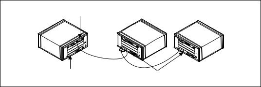
∙An embedded controller in one frame that is connected to other frames via mainframe extenders using MXI-2. VXI-MXI-2 or VME-MXI-2 boards in the other frames can also be used as remote controllers. See Figure 2-1.
Extender Only
Embedded Controller |
Extender and Remote Controller |
|
Figure 2-1. An Embedded Controller Connected to Other Frames via
Mainframe Extenders Using MXI-2
∙An external controller connected using MXI-2 to a number of remote controllers, each in a separate frame. The external controller can use the remote controllers for control of the VXI/VME system, or it can use its own controller capabilities. See Figure 2-2.
NI-VXI User Manual |
2-6 |
© National Instruments Corporation |

Chapter 2 Introduction to the NI-VXI Functions
External |
Remote Controller |
Extender |
Remote Controller |
Controller |
and Extender |
Only |
and Extender |
Figure 2-2. An External Controller Connected Using MXI-2 to a
Number of Remote Controllers
The extender and controller Parameters
In NI-VXI, some functions require a parameter named extender or controller. Since some extenders act as controllers, there is often confusion concerning what logical addresses should be passed to these functions.
The extender parameter is the logical address of a mainframe extender on which the function should be performed. Usually, functions with an extender parameter involve the mapping of interrupt lines or trigger lines into or out of a frame.
The controller parameter is the logical address of an embedded, external, extending, or remote controller. Usually, functions with a controller parameter involve sourcing or sensing particular interrupts or triggers in a frame. According to the definitions of the different types of controllers, the only valid logical addresses for the controller parameter are:
∙The external or embedded controller on which the program is running
∙A parent-side VXI-MXI-2 or VME-MXI-2 in a frame
© National Instruments Corporation |
2-7 |
NI-VXI User Manual |
Chapter 2 Introduction to the NI-VXI Functions
Most functions that take a controller parameter will allow you to pass (-1) as the logical address. This selects the default controller for the system. Notice that the default controller is determined by the following factors:
∙If the program is running on an embedded controller, the default controller is the embedded controller.
∙If the program is running on an external controller, you will be able to configure whether the default controller is the external controller or the remote controller with the lowest numbered logical address. With this behavior, if you write a program on an embedded controller referring to the controller as logical address-1, you will be able to swap the embedded controller configuration with an external controller configuration without changing your source code.
Notice that -1 is never a valid value for the extender parameter. In addition, the logical addresses of embedded and external controllers also are never valid values for the extender parameter. The extender parameter refers only to devices that can map interrupt lines, trigger lines, or other signals into or out of a frame.
NI-VXI User Manual |
2-8 |
© National Instruments Corporation |

Chapter 2 Introduction to the NI-VXI Functions
Using NI-VXI
This section presents a general overview of the more commonly used class of functions available in NI-VXI. Additional information summarizes how you can use the functions to perform certain tasks and further describes the general structure of NI-VXI programming.
Header Files
Although nivxi.h is the only header file you need to include in your program for NI-VXI, the software distribution actually includes several additional header files along with nivxi.h. Some of these files have type definitions and macros that can make using NI-VXI easier, and make the code more portable across different platforms. The three main files of interest are datasize.h, busacc.h, and devinfo.h.
The datasize.h File
The datasize.h file defines the integer types for use in your program. For example, INT16 is defined as a 16-bit signed integer, and UINT32 is defined as a 32-bit unsigned integer. Using these types benefits you by letting you apply specific type sizes across platforms. Using undefined types can cause problems when porting your application between platforms. For example, an int in DOS is a 16-bit number but a 32-bit number in Solaris or LabWindows/CVI.
In addition to the integers, datasize.h defines several types for other uses such as interrupt handlers. For example, NIVXI_HVXIINT is an interrupt handler type. Merely defining a variable with this type is sufficient to create the function prototype necessary for your interrupt handler. Also, different platforms require different flags for use with interrupt handlers. To simplify this problem, datasize.h defines NIVXI_HQUAL and NIVXI_HSPEC, which are used in the handler definition and take care of the platform dependencies. See the Interrupts and Signals section later in this chapter and your read me file for more information. In addition, refer to Chapter 3, Software Overview for specific information.
© National Instruments Corporation |
2-9 |
NI-VXI User Manual |
Chapter 2 Introduction to the NI-VXI Functions
The busacc.h File
The busacc.h file defines constants and macros for use with the high/low-level and slave memory access functions (see the Master Memory Access and Slave Memory Access sections later in this chapter). To make the code more readable, busacc.h defines such elements as memory space, privilege mode, and byte order as constants, and it defines macros to combine these constants into the necessary access parameters. Examine the header file for more information on the available macros and constants. You can see these tools in use by reviewing the example programs on memory accesses that appear later in this chapter and also the example programs included with your software.
The devinfo.h File
The devinfo.h file contains a data type that is used with the GetDevInfo()function described in the System Configuration Functions section in Chapter 3, Software Overview. The purpose of this function is to return various information about the system. GetDevInfo()can return the information either a piece at a time, or in one large data structure. The header file devinfo.h contains the type UserLAEntry, which defines the data structure that the function uses. Refer to the header file for the exact definition of the data structure.
The Beginning and End of an NI-VXI Program
All NI-VXI programs must call InitVXIlibrary() to initialize the driver before using any other functions. You must call CloseVXIlibrary() before exiting from your program to free resources associated with NI-VXI. The first function creates the internal structure needed to make the NI-VXI interface operational. When InitVXIlibrary() completes its initialization procedures, other functions can access information obtained by RESMAN, the VXIbus Resource Manager, as well as use other NI-VXI features such as interrupt handlers and windows for memory access. The second function destroys this structure and frees the associated memory. All programs using NI-VXI must call InitVXIlibrary() before any other NI-VXI function. In addition, your program should include a call to CloseVXIlibrary() before exiting.
NI-VXI User Manual |
2-10 |
© National Instruments Corporation |

Chapter 2 Introduction to the NI-VXI Functions
An important note about these two functions is that the internal structure maintains a record of the number of calls to
InitVXIlibrary() and CloseVXIlibrary(). Although
InitVXIlibrary() needs to be called only once, the structure of your program may cause the function to be called multiple times. A successful call to InitVXIlibrary() returns either a zero or a one. A zero indicates that the structure has been created, and a one indicates that the structure was created by an earlier call so no action was taken (other than incrementing the count of the number of
InitVXIlibrary() calls).
When CloseVXIlibrary() returns a successful code, it also returns either a zero or a one. A zero indicates that the structure has been successfully destroyed, and a one indicates that there are still outstanding calls to InitVXIlibrary() that must be closed before the structure is destroyed. The outcome of all of this is that when exiting a program, you should call CloseVXIlibrary() the same number of times that you have called InitVXIlibrary().
Caution: In environments where all applications share NI-VXI, and hence the internal structure (such as Microsoft Windows), it can be dangerous for any one application to call CloseVXIlibrary() until it returns zero because this can close out the structure from under another application. It is vital to keep track of the number of times you have called
InitVXIlibrary().
System Configuration Tools
The System Configuration Functions section of Chapter 3, Software Overview, describes functions that a program can use to access information about the system. This is obtained either through configuration information or from information obtained by RESMAN. Armed with these functions, a program can be more flexible to changes within the system.
Note: The examples in this manual do not check for either warnings or errors in most of the functions’ return codes. This step is omitted only to simplify the example programs. We strongly recommend that you include error checking in your own programs.
© National Instruments Corporation |
2-11 |
NI-VXI User Manual |
 Loading...