


DAQ M Series
NI USB-621x User Manual
Bus-Powered M Series USB Devices
August 2006 371931A-01
Worldwide Technical Support and Product Information
ni.com
National Instruments Corporate Headquarters
11500 North Mopac Expressway Austin, Texas 78759-3504 USA Tel: 512 683 0100
Worldwide Offices
Australia 1800 300 800, Austria 43 0 662 45 79 90 0, Belgium 32 0 2 757 00 20, Brazil 55 11 3262 3599, Canada 800 433 3488, China 86 21 6555 7838, Czech Republic 420 224 235 774, Denmark 45 45 76 26 00, Finland 385 0 9 725 725 11, France 33 0 1 48 14 24 24, Germany 49 0 89 741 31 30, India 91 80 41190000, Israel 972 0 3 6393737, Italy 39 02 413091, Japan 81 3 5472 2970, Korea 82 02 3451 3400,
Lebanon 961 0 1 33 28 28, Malaysia 1800 887710, Mexico 01 800 010 0793, Netherlands 31 0 348 433 466, New Zealand 0800 553 322, Norway 47 0 66 90 76 60, Poland 48 22 3390150, Portugal 351 210 311 210, Russia 7 095 783 68 51, Singapore 1800 226 5886, Slovenia 386 3 425 4200, South Africa 27 0 11 805 8197, Spain 34 91 640 0085, Sweden 46 0 8 587 895 00, Switzerland 41 56 200 51 51, Taiwan 886 02 2377 2222, Thailand 662 278 6777, United Kingdom 44 0 1635 523545
For further support information, refer to the Technical Support and Professional Services appendix. To comment on National Instruments documentation, refer to the National Instruments Web site at ni.com/info and enter the info code feedback.
© 2006 National Instruments Corporation. All rights reserved.

Important Information
Warranty
The USB-6210, USB-6211, USB-6215, and USB-6218 devices are warranted against defects in materials and workmanship for a period of three years from the date of shipment, as evidenced by receipts or other documentation. National Instruments will, at its option, repair or replace equipment that proves to be defective during the warranty period. This warranty includes parts and labor.
The media on which you receive National Instruments software are warranted not to fail to execute programming instructions, due to defects in materials and workmanship, for a period of 90 days from date of shipment, as evidenced by receipts or other documentation. National Instruments will, at its option, repair or replace software media that do not execute programming instructions if National Instruments receives notice of such defects during the warranty period. National Instruments does not warrant that the operation of the software shall be uninterrupted or error free.
A Return Material Authorization (RMA) number must be obtained from the factory and clearly marked on the outside of the package before any equipment will be accepted for warranty work. National Instruments will pay the shipping costs of returning to the owner parts which are covered by warranty.
National Instruments believes that the information in this document is accurate. The document has been carefully reviewed for technical accuracy. In the event that technical or typographical errors exist, National Instruments reserves the right to make changes to subsequent editions of this document without prior notice to holders of this edition. The reader should consult National Instruments if errors are suspected. In no event shall National Instruments be liable for any damages arising out of or related to this document or the information contained in it.
EXCEPT AS SPECIFIED HEREIN, NATIONAL INSTRUMENTS MAKES NO WARRANTIES, EXPRESS OR IMPLIED, AND SPECIFICALLY DISCLAIMS ANY WARRANTY OF MERCHANTABILITY OR FITNESS FOR A PARTICULAR PURPOSE. CUSTOMER’S RIGHT TO RECOVER DAMAGES CAUSED BY FAULT OR NEGLIGENCE ON THE PART OF NATIONAL
INSTRUMENTS SHALL BE LIMITED TO THE AMOUNT THERETOFORE PAID BY THE CUSTOMER. NATIONAL INSTRUMENTS WILL NOT BE LIABLE FOR DAMAGES RESULTING FROM LOSS OF DATA, PROFITS, USE OF PRODUCTS, OR INCIDENTAL OR CONSEQUENTIAL DAMAGES, EVEN IF ADVISED OF THE POSSIBILITY THEREOF. This limitation of
the liability of National Instruments will apply regardless of the form of action, whether in contract or tort, including negligence. Any action against National Instruments must be brought within one year after the cause of action accrues. National Instruments shall not be liable for any delay in performance due to causes beyond its reasonable control. The warranty provided herein does not cover damages, defects, malfunctions, or service failures caused by owner’s failure to follow the National Instruments installation, operation, or maintenance instructions; owner’s modification of the product; owner’s abuse, misuse, or negligent acts; and power failure or surges, fire, flood, accident, actions of third parties, or other events outside reasonable control.
Copyright
Under the copyright laws, this publication may not be reproduced or transmitted in any form, electronic or mechanical, including photocopying, recording, storing in an information retrieval system, or translating, in whole or in part, without the prior written consent of National Instruments Corporation.
National Instruments respects the intellectual property of others, and we ask our users to do the same. NI software is protected by copyright and other intellectual property laws. Where NI software may be used to reproduce software or other materials belonging to others, you may use NI software only to reproduce materials that you may reproduce in accordance with the terms of any applicable license or other legal restriction.
Trademarks
National Instruments, NI, ni.com, and LabVIEW are trademarks of National Instruments Corporation. Refer to the Terms of Use section on ni.com/legal for more information about National Instruments trademarks.
FireWire® is the registered trademark of Apple Computer, Inc. Other product and company names mentioned herein are trademarks or trade names of their respective companies.
Members of the National Instruments Alliance Partner Program are business entities independent from National Instruments and have no agency, partnership, or joint-venture relationship with National Instruments.
Patents
For patents covering National Instruments products, refer to the appropriate location: Help»Patents in your software, the patents.txt file on your CD, or ni.com/patents.
WARNING REGARDING USE OF NATIONAL INSTRUMENTS PRODUCTS
(1)NATIONAL INSTRUMENTS PRODUCTS ARE NOT DESIGNED WITH COMPONENTS AND TESTING FOR A LEVEL OF RELIABILITY SUITABLE FOR USE IN OR IN CONNECTION WITH SURGICAL IMPLANTS OR AS CRITICAL COMPONENTS IN ANY LIFE SUPPORT SYSTEMS WHOSE FAILURE TO PERFORM CAN REASONABLY BE EXPECTED TO CAUSE SIGNIFICANT INJURY TO A HUMAN.
(2)IN ANY APPLICATION, INCLUDING THE ABOVE, RELIABILITY OF OPERATION OF THE SOFTWARE PRODUCTS CAN BE IMPAIRED BY ADVERSE FACTORS, INCLUDING BUT NOT LIMITED TO FLUCTUATIONS IN ELECTRICAL POWER SUPPLY, COMPUTER HARDWARE MALFUNCTIONS, COMPUTER OPERATING SYSTEM SOFTWARE FITNESS, FITNESS OF COMPILERS AND DEVELOPMENT SOFTWARE USED TO DEVELOP AN APPLICATION, INSTALLATION ERRORS, SOFTWARE AND HARDWARE COMPATIBILITY PROBLEMS, MALFUNCTIONS OR FAILURES OF ELECTRONIC MONITORING OR CONTROL DEVICES, TRANSIENT FAILURES OF ELECTRONIC SYSTEMS (HARDWARE AND/OR SOFTWARE), UNANTICIPATED USES OR MISUSES, OR ERRORS ON THE PART OF THE USER OR APPLICATIONS DESIGNER (ADVERSE FACTORS SUCH AS THESE ARE HEREAFTER COLLECTIVELY TERMED “SYSTEM FAILURES”). ANY APPLICATION WHERE A SYSTEM FAILURE WOULD CREATE A RISK OF HARM TO PROPERTY OR PERSONS (INCLUDING THE RISK OF BODILY INJURY AND DEATH) SHOULD NOT BE RELIANT SOLELY UPON ONE FORM OF ELECTRONIC SYSTEM DUE TO THE RISK OF SYSTEM FAILURE. TO AVOID DAMAGE, INJURY, OR DEATH, THE USER OR APPLICATION DESIGNER MUST TAKE REASONABLY PRUDENT STEPS TO PROTECT AGAINST SYSTEM FAILURES, INCLUDING BUT NOT LIMITED TO BACK-UP OR SHUT DOWN MECHANISMS. BECAUSE EACH END-USER SYSTEM IS CUSTOMIZED AND DIFFERS FROM NATIONAL INSTRUMENTS' TESTING PLATFORMS AND BECAUSE A USER OR APPLICATION DESIGNER MAY USE NATIONAL INSTRUMENTS PRODUCTS IN COMBINATION WITH OTHER PRODUCTS IN A MANNER NOT EVALUATED OR CONTEMPLATED BY NATIONAL INSTRUMENTS, THE USER OR APPLICATION DESIGNER IS ULTIMATELY RESPONSIBLE FOR VERIFYING AND VALIDATING THE SUITABILITY OF NATIONAL INSTRUMENTS PRODUCTS WHENEVER
NATIONAL INSTRUMENTS PRODUCTS ARE INCORPORATED IN A SYSTEM OR APPLICATION, INCLUDING, WITHOUT LIMITATION, THE APPROPRIATE DESIGN, PROCESS AND SAFETY LEVEL OF SUCH SYSTEM OR APPLICATION.

Contents
About This Manual
Conventions ................................................................................................................... |
xiii |
Related Documentation.................................................................................................. |
xiv |
NI-DAQmx for Windows................................................................................ |
xiv |
LabVIEW ........................................................................................................ |
xiv |
LabWindows™/CVI™.................................................................................... |
xv |
Measurement Studio........................................................................................ |
xv |
ANSI C without NI Application Software ...................................................... |
xv |
.NET Languages without NI Application Software ........................................ |
xvi |
Device Documentation and Specifications...................................................... |
xvi |
Training Courses ............................................................................................. |
xvi |
Technical Support on the Web ........................................................................ |
xvi |
Chapter 1
Getting Started
Installing NI-DAQmx .................................................................................................... |
1-2 |
Installing Other Software............................................................................................... |
1-2 |
Installing the Hardware.................................................................................................. |
1-3 |
Device Pinouts ............................................................................................................... |
1-3 |
Device Specifications .................................................................................................... |
1-3 |
Device Accessories ........................................................................................................ |
1-3 |
Chapter 2
DAQ System Overview
DAQ Hardware .............................................................................................................. |
2-1 |
DAQ-STC2...................................................................................................... |
2-2 |
Calibration Circuitry........................................................................................ |
2-2 |
Signal Conditioning ....................................................................................................... |
2-3 |
Sensors and Transducers ................................................................................. |
2-3 |
Programming Devices in Software ................................................................................ |
2-4 |
Chapter 3
Connector Information
I/O Connector Signal Descriptions ................................................................................ |
3-1 |
|
+5 V Power |
.................................................................................................................... |
3-2 |
+5 |
V Power as an Output ................................................................................ |
3-2 |
+5 |
V Power as an Input ................................................................................... |
3-3 |
© National Instruments Corporation |
v |
NI USB-621x User Manual |
Contents
Chapter 4
Analog Input
Analog Input Circuitry .................................................................................................. |
4-1 |
Analog Input Range....................................................................................................... |
4-2 |
Analog Input Ground-Reference Settings ..................................................................... |
4-3 |
Configuring AI Ground-Reference Settings in Software................................ |
4-5 |
Multichannel Scanning Considerations......................................................................... |
4-6 |
Use Low Impedance Sources.......................................................................... |
4-6 |
Carefully Choose the Channel Scanning Order .............................................. |
4-7 |
Avoid Switching from a Large to a Small Input Range ................... |
4-7 |
Insert Grounded Channel between Signal Channels ........................ |
4-7 |
Minimize Voltage Step between Adjacent Channels ....................... |
4-8 |
Avoid Scanning Faster Than Necessary ......................................................... |
4-8 |
Example 1 ......................................................................................... |
4-8 |
Example 2 ......................................................................................... |
4-9 |
Analog Input Data Acquisition Methods....................................................................... |
4-9 |
Software-Timed Acquisitions ......................................................................... |
4-9 |
Hardware-Timed Acquisitions........................................................................ |
4-9 |
Buffered ............................................................................................ |
4-10 |
Non-Buffered.................................................................................... |
4-10 |
Analog Input Digital Triggering.................................................................................... |
4-10 |
Field Wiring Considerations.......................................................................................... |
4-11 |
Analog Input Timing Signals ........................................................................................ |
4-11 |
AI Sample Clock Signal.................................................................................. |
4-14 |
Using an Internal Source .................................................................. |
4-15 |
Using an External Source ................................................................. |
4-15 |
Routing AI Sample Clock Signal to an Output Terminal................. |
4-15 |
Other Timing Requirements ............................................................. |
4-15 |
AI Sample Clock Timebase Signal ................................................................. |
4-16 |
AI Convert Clock Signal................................................................................. |
4-16 |
Using an Internal Source .................................................................. |
4-17 |
Using an External Source ................................................................. |
4-17 |
Routing AI Convert Clock Signal to an Output Terminal................ |
4-17 |
Using a Delay from Sample Clock to Convert Clock ...................... |
4-17 |
Other Timing Requirements ............................................................. |
4-18 |
AI Convert Clock Timebase Signal ................................................................ |
4-20 |
AI Hold Complete Event Signal ..................................................................... |
4-21 |
AI Start Trigger Signal.................................................................................... |
4-21 |
Using a Digital Source...................................................................... |
4-21 |
Routing AI Start Trigger to an Output Terminal .............................. |
4-21 |
AI Reference Trigger Signal ........................................................................... |
4-22 |
Using a Digital Source...................................................................... |
4-23 |
Routing AI Reference Trigger Signal to an Output Terminal .......... |
4-23 |
NI USB-621x User Manual |
vi |
ni.com |
|
Contents |
AI Pause Trigger Signal .................................................................................. |
4-23 |
Using a Digital Source ...................................................................... |
4-23 |
Getting Started with AI Applications in Software......................................................... |
4-24 |
Chapter 5 |
|
Connecting AI Signals on the USB-6210/6211 Devices |
|
Connecting Floating Signal Sources.............................................................................. |
5-3 |
What Are Floating Signal Sources? ................................................................ |
5-3 |
When to Use Differential Connections with Floating Signal Sources ............ |
5-3 |
When to Use Referenced Single-Ended (RSE) Connections with |
|
Floating Signal Sources ................................................................................ |
5-3 |
When to Use Non-Referenced Single-Ended (NRSE) Connections |
|
with Floating Signal Sources........................................................................ |
5-4 |
Using Differential Connections for Floating Signal Sources .......................... |
5-5 |
Using Non-Referenced Single-Ended (NRSE) Connections for |
|
Floating Signal Sources ................................................................................ |
5-8 |
Using Referenced Single-Ended (RSE) Connections for Floating |
|
Signal Sources .............................................................................................. |
5-9 |
Connecting Ground-Referenced Signal Sources ........................................................... |
5-9 |
What Are Ground-Referenced Signal Sources? .............................................. |
5-9 |
When to Use Differential Connections with Ground-Referenced |
|
Signal Sources .............................................................................................. |
5-10 |
When to Use Non-Referenced Single-Ended (NRSE) Connections with |
|
Ground-Referenced Signal Sources.............................................................. |
5-10 |
When to Use Referenced Single-Ended (RSE) Connections with |
|
Ground-Referenced Signal Sources.............................................................. |
5-11 |
Using Differential Connections for Ground-Referenced Signal Sources........ |
5-12 |
Using Non-Referenced Single-Ended (NRSE) Connections for |
|
Ground-Referenced Signal Sources.............................................................. |
5-13 |
Chapter 6 |
|
Connecting AI Signals on the USB-6215/6218 Devices |
|
Differential Measurements ............................................................................................ |
6-1 |
Differential Pairs............................................................................................................ |
6-1 |
Referenced Single-Ended (RSE) Measurements ........................................................... |
6-3 |
Non-Referenced Single-Ended (NRSE) Measurements ................................................ |
6-4 |
© National Instruments Corporation |
vii |
NI USB-621x User Manual |
Contents
Chapter 7
Analog Output
Analog Output Circuitry................................................................................................ |
7-1 |
AO Range ...................................................................................................................... |
7-2 |
Minimizing Glitches on the Output Signal.................................................................... |
7-2 |
Analog Output Data Generation Methods..................................................................... |
7-2 |
Software-Timed Generations .......................................................................... |
7-2 |
Hardware-Timed Generations......................................................................... |
7-2 |
Analog Output Digital Triggering ................................................................................. |
7-4 |
Connecting Analog Output Signals ............................................................................... |
7-4 |
Analog Output Timing Signals...................................................................................... |
7-5 |
AO Start Trigger Signal .................................................................................. |
7-5 |
Using a Digital Source...................................................................... |
7-5 |
Routing AO Start Trigger Signal to an Output Terminal ................. |
7-6 |
AO Pause Trigger Signal ................................................................................ |
7-6 |
Using a Digital Source...................................................................... |
7-6 |
AO Sample Clock Signal ................................................................................ |
7-7 |
Using an Internal Source .................................................................. |
7-7 |
Using an External Source ................................................................. |
7-7 |
Routing AO Sample Clock Signal to an Output Terminal ............... |
7-7 |
Other Timing Requirements ............................................................. |
7-7 |
AO Sample Clock Timebase Signal................................................................ |
7-8 |
Getting Started with AO Applications in Software....................................................... |
7-9 |
Chapter 8
Digital I/O
Static DIO...................................................................................................................... |
8-2 |
I/O Protection ................................................................................................................ |
8-2 |
Increasing Current Drive ............................................................................................... |
8-2 |
Connecting Digital I/O Signals ..................................................................................... |
8-3 |
Getting Started with DIO Applications in Software...................................................... |
8-4 |
Chapter 9
Counters
Counter Input Applications ........................................................................................... |
9-2 |
Counting Edges ............................................................................................... |
9-2 |
Single Point (On-Demand) Edge Counting ...................................... |
9-2 |
Buffered (Sample Clock) Edge Counting......................................... |
9-3 |
Non-Cumulative Buffered Edge Counting ....................................... |
9-4 |
Controlling the Direction of Counting.............................................. |
9-4 |
NI USB-621x User Manual |
viii |
ni.com |
|
Contents |
Pulse-Width Measurement .............................................................................. |
9-5 |
Single Pulse-Width Measurement..................................................... |
9-5 |
Buffered Pulse-Width Measurement................................................. |
9-5 |
Period Measurement........................................................................................ |
9-6 |
Single Period Measurement .............................................................. |
9-7 |
Buffered Period Measurement .......................................................... |
9-7 |
Semi-Period Measurement .............................................................................. |
9-9 |
Single Semi-Period Measurement..................................................... |
9-9 |
Buffered Semi-Period Measurement................................................. |
9-9 |
Frequency Measurement ................................................................................. |
9-10 |
Method 1—Measure Low Frequency with One Counter.................. |
9-10 |
Method 1b—Measure Low Frequency with One Counter |
|
(Averaged)...................................................................................... |
9-11 |
Method 2—Measure High Frequency with Two Counters............... |
9-11 |
Method 3—Measure Large Range of Frequencies Using |
|
Two Counters ................................................................................. |
9-12 |
Choosing a Method for Measuring Frequency ................................. |
9-13 |
Position Measurement ..................................................................................... |
9-15 |
Measurements Using Quadrature Encoders...................................... |
9-15 |
Measurements Using Two Pulse Encoders....................................... |
9-17 |
Two-Signal Edge-Separation Measurement.................................................... |
9-18 |
Single Two-Signal Edge-Separation Measurement .......................... |
9-18 |
Buffered Two-Signal Edge-Separation Measurement ...................... |
9-19 |
Counter Output Applications ......................................................................................... |
9-20 |
Simple Pulse Generation ................................................................................. |
9-20 |
Single Pulse Generation .................................................................... |
9-20 |
Single Pulse Generation with Start Trigger ...................................... |
9-20 |
Retriggerable Single Pulse Generation ............................................. |
9-21 |
Pulse Train Generation .................................................................................... |
9-22 |
Continuous Pulse Train Generation .................................................. |
9-22 |
Frequency Generation ..................................................................................... |
9-23 |
Using the Frequency Generator ........................................................ |
9-23 |
Frequency Division ......................................................................................... |
9-24 |
Pulse Generation for ETS................................................................................ |
9-24 |
Counter Timing Signals ................................................................................................. |
9-25 |
Counter n Source Signal.................................................................................. |
9-26 |
Routing a Signal to Counter n Source............................................... |
9-26 |
Routing Counter n Source to an Output Terminal ............................ |
9-26 |
Counter n Gate Signal ..................................................................................... |
9-27 |
Routing a Signal to Counter n Gate .................................................. |
9-27 |
Routing Counter n Gate to an Output Terminal................................ |
9-27 |
Counter n Aux Signal ...................................................................................... |
9-27 |
Routing a Signal to Counter n Aux................................................... |
9-27 |
© National Instruments Corporation |
ix |
NI USB-621x User Manual |
Contents
Counter n A, Counter n B, and Counter n Z Signals ...................................... |
9-28 |
Routing Signals to A, B, and Z Counter Inputs................................ |
9-28 |
Counter n Up_Down Signal............................................................................ |
9-28 |
Counter n HW Arm Signal.............................................................................. |
9-28 |
Routing Signals to Counter n HW Arm Input .................................. |
9-28 |
Counter n Internal Output and Counter n TC Signals..................................... |
9-29 |
Routing Counter n Internal Output to an Output Terminal .............. |
9-29 |
Frequency Output Signal ................................................................................ |
9-29 |
Routing Frequency Output to a Terminal......................................... |
9-29 |
Default Counter/Timer Pinouts ..................................................................................... |
9-29 |
Counter Triggering ........................................................................................................ |
9-31 |
Arm Start Trigger............................................................................................ |
9-31 |
Start Trigger .................................................................................................... |
9-31 |
Pause Trigger .................................................................................................. |
9-31 |
Other Counter Features.................................................................................................. |
9-32 |
Sample Clock .................................................................................................. |
9-32 |
Cascading Counters......................................................................................... |
9-33 |
Counter Filters................................................................................................. |
9-33 |
Prescaling ........................................................................................................ |
9-34 |
Duplicate Count Prevention ............................................................................ |
9-35 |
Example Application That Works Correctly |
|
(No Duplicate Counting) ............................................................... |
9-36 |
Example Application That Works Incorrectly |
|
(Duplicate Counting) ..................................................................... |
9-37 |
Example Application That Prevents Duplicate Count...................... |
9-37 |
Enabling Duplicate Count Prevention in NI-DAQmx...................... |
9-38 |
Chapter 10
PFI
Using PFI Terminals as Timing Input Signals .............................................................. |
10-2 |
Exporting Timing Output Signals Using PFI Terminals............................................... |
10-3 |
Using PFI Terminals as Static Digital I/Os ................................................................... |
10-3 |
Connecting PFI Input Signals........................................................................................ |
10-3 |
PFI Filters ...................................................................................................................... |
10-4 |
I/O Protection ................................................................................................................ |
10-6 |
Programmable Power-Up States.................................................................................... |
10-6 |
NI USB-621x User Manual |
x |
ni.com |
|
Contents |
Chapter 11 |
|
Isolation and Digital Isolators |
|
Digital Isolation ............................................................................................................. |
11-2 |
Benefits of an Isolated DAQ Device ............................................................................. |
11-2 |
Reducing Common-Mode Noise ................................................................................... |
11-2 |
Creating an AC Return Path ............................................................................ |
11-3 |
Isolated Systems................................................................................ |
11-3 |
Non-Isolated Systems ....................................................................... |
11-3 |
Chapter 12 |
|
Digital Routing and Clock Generation |
|
80 MHz Timebase.......................................................................................................... |
12-1 |
20 MHz Timebase.......................................................................................................... |
12-1 |
100 kHz Timebase ......................................................................................................... |
12-2 |
Chapter 13 |
|
Bus Interface |
|
USB Signal Streams....................................................................................................... |
13-1 |
Data Transfer Methods .................................................................................................. |
13-1 |
USB Signal Stream.......................................................................................... |
13-1 |
Programmed I/O .............................................................................................. |
13-2 |
Changing Data Transfer Methods ................................................................... |
13-2 |
Chapter 14 |
|
Triggering |
|
Triggering with a Digital Source ................................................................................... |
14-1 |
Appendix A |
|
Device-Specific Information |
|
USB-6210 ...................................................................................................................... |
A-1 |
USB-6211/6215 ............................................................................................................. |
A-4 |
USB 6218....................................................................................................................... |
A-7 |
© National Instruments Corporation |
xi |
NI USB-621x User Manual |
Contents
Appendix B
Troubleshooting
Appendix C
Technical Support and Professional Services
Glossary
Index
Device Pinouts
Figure A-1. |
USB-6210 Pinout .................................................................................. |
A-2 |
Figure A-2. |
USB-6211/6215 Pinout......................................................................... |
A-5 |
Figure A-3. |
USB 6218 Pinout .................................................................................. |
A-8 |
NI USB-621x User Manual |
xii |
ni.com |

About This Manual
|
The NI 621x User Manual contains information about using the National |
|
Instruments USB-621x data acquisition (DAQ) devices with |
|
NI-DAQmx 8.3 and later. NI 621x devices feature up to 32 analog input |
|
(AI) channels, up to two analog output (AO) channels, up to eight lines of |
|
digital input (DI), up to eight lines of digital output (DO), and two counters. |
Conventions |
|
|
|
|
The following conventions are used in this manual: |
<> |
Angle brackets that contain numbers separated by an ellipsis represent |
|
a range of values associated with a bit or signal name—for example, |
|
AO <3..0>. |
» |
The » symbol leads you through nested menu items and dialog box options |
|
to a final action. The sequence File»Page Setup»Options directs you to |
|
pull down the File menu, select the Page Setup item, and select Options |
|
from the last dialog box. |
|
This icon denotes a note, which alerts you to important information. |
|
This icon denotes a caution, which advises you of precautions to take to |
|
avoid injury, data loss, or a system crash. When this symbol is marked on a |
|
product, refer to the Read Me First: Safety and Radio-Frequency |
|
Interference document which can be found at ni.com/manuals, for |
|
information about precautions to take. |
bold |
Bold text denotes items that you must select or click in the software, such |
|
as menu items and dialog box options. Bold text also denotes parameter |
|
names. |
italic |
Italic text denotes variables, emphasis, a cross-reference, or an introduction |
|
to a key concept. Italic text also denotes text that is a placeholder for a word |
|
or value that you must supply. |
monospace |
Text in this font denotes text or characters that you should enter from the |
|
keyboard, sections of code, programming examples, and syntax examples. |
|
This font is also used for the proper names of disk drives, paths, directories, |
|
programs, subprograms, subroutines, device names, functions, operations, |
|
variables, filenames, and extensions. |
© National Instruments Corporation |
xiii |
NI USB-621x User Manual |

About This Manual
Related Documentation
Each application software package and driver includes information about writing applications for taking measurements and controlling measurement devices. The following references to documents assume you have NI-DAQ 8.3 or later, and where applicable, version 7.0 or later of the NI application software.
NI-DAQmx for Windows
The NI-DAQmx for USB Devices Getting Started Guide describes how to install your NI-DAQmx for Windows software, your
NI-DAQmx-supported DAQ device, and how to confirm that your device is operating properly. Select Start»All Programs»National Instruments» NI-DAQ»NI-DAQmx for USB Devices Getting Started.
The NI-DAQ Readme lists which devices are supported by this version of
NI-DAQ. Select Start»All Programs»National Instruments»NI-DAQ»
NI-DAQ Readme.
The NI-DAQmx Help contains general information about measurement concepts, key NI-DAQmx concepts, and common applications that are applicable to all programming environments. Select Start»All Programs» National Instruments»NI-DAQ»NI-DAQmx Help.
LabVIEW
If you are a new user, use the Getting Started with LabVIEW manual to familiarize yourself with the LabVIEW graphical programming environment and the basic LabVIEW features you use to build data acquisition and instrument control applications. Open the Getting Started with LabVIEW manual by selecting Start»All Programs»National Instruments»LabVIEW»LabVIEW Manuals or by navigating to the labview\manuals directory and opening
LV_Getting_Started.pdf.
Use the LabVIEW Help, available by selecting Help»Search the LabVIEW Help in LabVIEW, to access information about LabVIEW programming concepts, step-by-step instructions for using LabVIEW, and reference information about LabVIEW VIs, functions, palettes, menus, and
NI USB-621x User Manual |
xiv |
ni.com |

About This Manual
tools. Refer to the following locations on the Contents tab of the LabVIEW Help for information about NI-DAQmx:
•Getting Started»Getting Started with DAQ—Includes overview information and a tutorial to learn how to take an NI-DAQmx measurement in LabVIEW using the DAQ Assistant.
•VI and Function Reference»Measurement I/O VIs and Functions—Describes the LabVIEW NI-DAQmx VIs and properties.
•Taking Measurements—Contains the conceptual and how-to information you need to acquire and analyze measurement data in LabVIEW, including common measurements, measurement fundamentals, NI-DAQmx key concepts, and device considerations.
LabWindows™/CVI™
The Data Acquisition book of the LabWindows/CVI Help contains measurement concepts for NI-DAQmx. This book also contains Taking an NI-DAQmx Measurement in LabWindows/CVI, which includes step-by-step instructions about creating a measurement task using the DAQ Assistant. In LabWindows/CVI, select Help»Contents, then select Using LabWindows/CVI»Data Acquisition.
The NI-DAQmx Library book of the LabWindows/CVI Help contains API overviews and function reference for NI-DAQmx. Select Library Reference»NI-DAQmx Library in the LabWindows/CVI Help.
Measurement Studio
The NI Measurement Studio Help contains function reference, measurement concepts, and a walkthrough for using the Measurement Studio NI-DAQmx .NET and Visual C++ class libraries. This help collection is integrated into the Microsoft Visual Studio .NET documentation. In Visual Studio .NET, select Help»Contents.
Note You must have Visual Studio .NET installed to view the NI Measurement Studio Help.
ANSI C without NI Application Software
The NI-DAQmx Help contains API overviews and general information about measurement concepts. Select Start»All Programs»National Instruments»NI-DAQmx Help.
© National Instruments Corporation |
xv |
NI USB-621x User Manual |

About This Manual
.NET Languages without NI Application Software
The NI Measurement Studio Help contains function reference and measurement concepts for using the Measurement Studio NI-DAQmx
.NET and Visual C++ class libraries. This help collection is integrated into the Visual Studio .NET documentation. In Visual Studio .NET, select
Help»Contents.
Note You must have Visual Studio .NET installed to view the NI Measurement Studio Help.
Device Documentation and Specifications
The NI 621x Specifications contains all specifications for the USB-6210,
USB-6211, USB-6215, and USB-6218 M Series devices.
NI-DAQ 7.0 and later includes the Device Document Browser, which contains online documentation for supported DAQ, SCXI, and switch devices, such as help files describing device pinouts, features, and operation, and PDF files of the printed device documents. You can find, view, and/or print the documents for each device using the Device Document Browser at any time by inserting the CD. After installing the Device Document Browser, device documents are accessible from Start»
All Programs»National Instruments»NI-DAQ»Browse Device Documentation.
Training Courses
If you need more help getting started developing an application with NI products, NI offers training courses. To enroll in a course or obtain a detailed course outline, refer to ni.com/training.
Technical Support on the Web
For additional support, refer to ni.com/support or zone.ni.com.
Note You can download these documents at ni.com/manuals.
DAQ specifications and some DAQ manuals are available as PDFs. You must have Adobe Acrobat Reader with Search and Accessibility 5.0.5 or later installed to view the PDFs. Refer to the Adobe Systems Incorporated Web site at www.adobe.com to download Acrobat Reader. Refer to the National Instruments Product Manuals Library at ni.com/manuals for updated documentation resources.
NI USB-621x User Manual |
xvi |
ni.com |

1
Getting Started
Figure 1-1. |
USB-6210/6211 |
© National Instruments Corporation |
1-1 |
NI USB-621x User Manual |

Chapter 1 Getting Started
Figure 1-2. |
USB-6215/6218 |
NI 621x devices feature up to 32 analog input (AI) channels, up to two analog output (AO) channels, 8 lines of digital input (DI), 8 lines of digital output (DO), and two counters. If you have not already installed your device, refer to the NI-DAQmx for USB Devices Getting Started Guide. For specifications, refer to the NI 621x Specifications document on ni.com/manuals.
Before installing your DAQ device, you must install the software you plan to use with the device.
Installing NI-DAQmx
The NI-DAQmx for USB Devices Getting Started Guide, which you can download at ni.com/manuals, offers NI-DAQmx users step-by-step instructions for installing software and hardware, configuring channels and tasks, and getting started developing an application.
Installing Other Software
If you are using other software, refer to the installation instructions that accompany your software.
NI USB-621x User Manual |
1-2 |
ni.com |

Chapter 1 Getting Started
Installing the Hardware
The NI-DAQmx for USB Devices Getting Started Guide contains non-software-specific information about how to install USB devices.
Device Pinouts
Refer to Appendix A, Device-Specific Information, for NI 621x device pinouts.
Device Specifications
Refer to the NI 621x Specifications, available on the NI-DAQ Device Document Browser or ni.com/manuals, for more detailed information about NI 621x devices.
Device Accessories
NI offers a variety of accessories to use with your DAQ device. Refer to Appendix A, Device-Specific Information, or ni.com for more information.
© National Instruments Corporation |
1-3 |
NI USB-621x User Manual |
2
DAQ System Overview
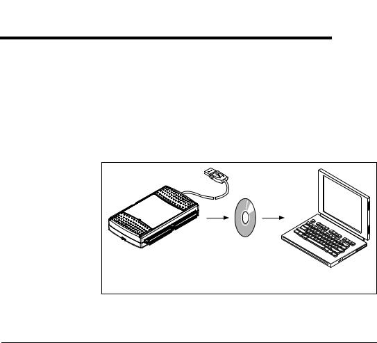
Figure 2-1 shows a typical DAQ system, which includes sensors, transducers, signal conditioning devices, cables that connect the various devices to the accessories, the M Series device, programming software, and PC. The following sections cover the components of a typical DAQ system.
DAQ |
DAQ |
Personal Computer |
Hardware |
Software |
or Laptop |
Figure 2-1. Components of a Typical DAQ System
DAQ Hardware
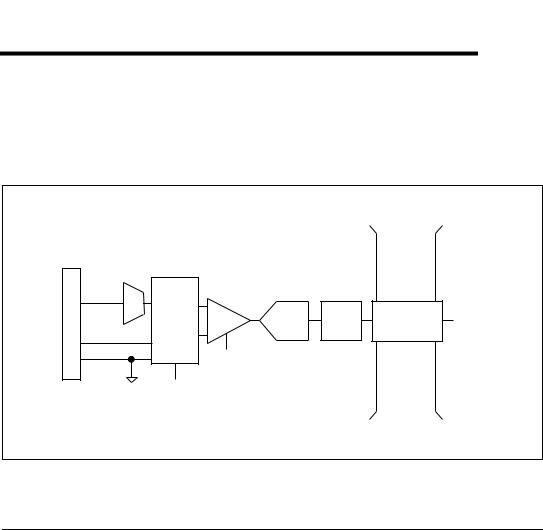
DAQ hardware digitizes signals, performs D/A conversions to generate analog output signals, and measures and controls digital I/O signals. Figure 2-2 features components common to all USB M Series devices.
© National Instruments Corporation |
2-1 |
NI USB-621x User Manual |
Chapter 2 DAQ System Overview
|
|
|
Isolation |
|
|
|
|
|
|
Barrier |
|
|
|
|
Analog Input |
|
(USB-6215 |
|
|
|
|
|
and USB-6218 |
|
|
||
|
|
|
|
|
||
|
|
|
devices only) |
|
|
|
|
Analog Output |
|
|
|
|
|
Connector |
|
Digital |
|
|
|
|
Digital I/O |
Routing |
Digital |
Bus |
Bus |
||
and Clock |
Isolators |
Interface |
||||
|
|
|||||
|
Generation |
|
|
|
||
I/O |
|
|
|
|
||
|
|
|
|
|
||
|
Counters |
|
|
|
|
|
|
PFI |
|
|
|
|
|
|
|
|
Figure 2-2. USB-621x Block Diagram |
|
||
DAQ-STC2
The DAQ-STC2 implements a high-performance digital engine for M Series data acquisition hardware. Some key features of this engine include the following:
•Flexible AI and AO sample and convert timing
•Many triggering modes
•Independent AI, AO, and CTR FIFOs
•Generation and routing of internal and external timing signals
•Two flexible 32-bit counter/timer modules with hardware gating
•Static DI and static DO signals
•USB Hi-Speed 2.0 interface
•Up to four USB Signal Streams for acquisition and generation functions
Calibration Circuitry
The M Series analog inputs and outputs have calibration circuitry to correct gain and offset errors. You can calibrate the device to minimize AI and AO errors caused by time and temperature drift at run time. No external circuitry is necessary; an internal reference ensures high accuracy and stability over time and temperature changes.
NI USB-621x User Manual |
2-2 |
ni.com |

Chapter 2 DAQ System Overview
Factory-calibration constants are permanently stored in an onboard EEPROM and cannot be modified. When you self-calibrate the device, software stores new constants in a user-modifiable section of the EEPROM. To return a device to its initial factory calibration settings, software can copy the factory-calibration constants to the user-modifiable section of the EEPROM. Refer to the NI-DAQmx Help or the LabVIEW 8.x Help for more information about using calibration constants.
Signal Conditioning
Many sensors and transducers require signal conditioning before a measurement system can effectively and accurately acquire the signal. The front-end signal conditioning system can include functions such as signal amplification, attenuation, filtering, electrical isolation, simultaneous sampling, and multiplexing. In addition, many transducers require excitation currents or voltages, bridge completion, linearization, or high amplification for proper and accurate operation. Therefore, most computer-based measurement systems include some form of signal conditioning in addition to plug-in data acquisition DAQ devices.
Sensors and Transducers
Sensors can generate electrical signals to measure physical phenomena, such as temperature, force, sound, or light. Some commonly used sensors are strain gauges, thermocouples, thermistors, angular encoders, linear encoders, and resistance temperature detectors (RTDs).
To measure signals from these various transducers, you must convert them into a form that a DAQ device can accept. For example, the output voltage of most thermocouples is very small and susceptible to noise. Therefore, you may need to amplify or filter the thermocouple output before digitizing it. The manipulation of signals to prepare them for digitizing is called signal conditioning.
For more information about sensors, refer to the following documents.
•For general information about sensors, visit ni.com/sensors.
•If you are using LabVIEW, refer to the LabVIEW Help by selecting Help»Search the LabVIEW Help in LabVIEW and then navigate to the Taking Measurements book on the Contents tab.
•If you are using other application software, refer to Common Sensors in the NI-DAQmx Help or the LabVIEW 8.x Help.
© National Instruments Corporation |
2-3 |
NI USB-621x User Manual |

Chapter 2 DAQ System Overview
Programming Devices in Software
National Instruments measurement devices are packaged with NI-DAQ driver software, an extensive library of functions and VIs you can call from your application software, such as LabVIEW or LabWindows/CVI, to program all the features of your NI measurement devices. Driver software has an application programming interface (API), which is a library of VIs, functions, classes, attributes, and properties for creating applications for your device.
NI-DAQ 7.3 and later includes two NI-DAQ drivers—Traditional NI-DAQ (Legacy) and NI-DAQmx. M Series devices use the NI-DAQmx driver. Each driver has its own API, hardware configuration, and software configuration. Refer to the NI-DAQmx for USB Devices Getting Started Guide for more information about the two drivers.
NI-DAQmx includes a collection of programming examples to help you get started developing an application. You can modify example code and save it in an application. You can use examples to develop a new application or add example code to an existing application.
To locate LabVIEW and LabWindows/CVI examples, open the National
Instruments Example Finder.
•In LabVIEW, select Help»Find Examples.
•In LabWindows/CVI, select Help»NI Example Finder.
Measurement Studio, Visual Basic, and ANSI C examples are located in the following directories:
•NI-DAQmx examples for Measurement Studio-supported languages are in the following directories:
–MeasurementStudio\VCNET\Examples\NIDaq
–MeasurementStudio\DotNET\Examples\NIDaq
•NI-DAQmx examples for ANSI C are in the
NI-DAQ\Examples\DAQmx ANSI C Dev directory
For additional examples, refer to zone.ni.com.
NI USB-621x User Manual |
2-4 |
ni.com |

3
Connector Information
The I/O Connector Signal Descriptions and +5 V Power sections contain information about NI 621x connectors. Refer to Appendix A, Device-Specific Information, for device I/O connector pinouts.
I/O Connector Signal Descriptions
Table 3-1 describes the signals found on the I/O connectors. Not all signals are available on all devices.
Table 3-1. I/O Connector Signals
Signal Name |
Reference |
Direction |
Description |
|
|
|
|
|
|
|
|
AI GND |
— |
— |
Analog Input Ground—These terminals are the |
|
|
|
reference point for single-ended AI measurements in |
|
|
|
RSE mode and the bias current return point for DIFF |
|
|
|
measurements. All three ground references—AI GND, |
|
|
|
AO GND, and D GND—are connected on the device. |
|
|
|
|
AI <0..31> |
Varies |
Input |
Analog Input Channels 0 to 31—For single-ended |
|
|
|
measurements, each signal is an analog input voltage |
|
|
|
channel. In RSE mode, AI GND is the reference for these |
|
|
|
signals. In NRSE mode, the reference for each |
|
|
|
AI <0..31> signal is AI SENSE. |
|
|
|
For differential measurements, AI 0 and AI 8 are the |
|
|
|
positive and negative inputs of differential analog input |
|
|
|
channel 0. Similarly, the following signal pairs also form |
|
|
|
differential input channels: |
|
|
|
<AI 1, AI 9>, <AI 2, AI 10>, <AI 3, AI 11>, |
|
|
|
<AI 4, AI 12>, <AI 5, AI 13>, <AI 6, AI 14>, |
|
|
|
<AI 7, AI 15>, <AI 16, AI 24>, <AI 17, AI 25>, |
|
|
|
<AI 18, AI 26>, <AI 19, AI 27>, <AI 20, AI 28>, |
|
|
|
<AI 21, AI 29>, <AI 22, AI 30>, <AI 23, AI 31> |
|
|
|
|
AI SENSE |
— |
Input |
Analog Input Sense—In NRSE mode, the reference for |
|
|
|
each AI <0..31> signal is AI SENSE. |
|
|
|
|
AO <0..1> |
AO GND |
Output |
Analog Output Channels 0 to 1—These terminals |
|
|
|
supply the voltage output of AO channels 0 to 1. |
|
|
|
|
© National Instruments Corporation |
3-1 |
NI USB-621x User Manual |

Chapter 3 Connector Information
Table 3-1. I/O Connector Signals (Continued)
Signal Name |
Reference |
Direction |
Description |
|
|
|
|
|
|
|
|
AO GND |
— |
— |
Analog Output Ground—AO GND is the reference for |
|
|
|
AO <0..1>. All three ground references—AI GND, |
|
|
|
AO GND, and D GND—are connected on the device. |
|
|
|
|
D GND |
— |
— |
Digital Ground—D GND supplies the reference for |
|
|
|
PFI <0..15>/P0/P1 and +5 V. All three ground |
|
|
|
references—AI GND, AO GND, and D GND—are |
|
|
|
connected on the device. |
|
|
|
|
+5 V |
D GND |
Input or |
+5 V Power—These terminals provide a +5 V power |
|
|
Output |
source or can be used to externally power the PFI outputs. |
|
|
|
|
PFI <0..3>, |
D GND |
Input |
Programmable Function Interface or Static Digital |
PFI <8..11>/P0.<0..7> |
|
|
Input Channels 0 to 7—Each PFI terminal can be used |
|
|
|
to supply an external source for AI, AO, or counter/timer |
|
|
|
inputs. |
|
|
|
You also can use these terminals as static digital input |
|
|
|
lines. |
|
|
|
|
PFI <4..7>, |
D GND |
Output |
Programmable Function Interface or Static Digital |
PFI <12..15>/P1.<0..7> |
|
|
Output Channels 0 to 7—You can route many different |
|
|
|
internal AI, AO, or counter/timer outputs to each PFI |
|
|
|
terminal. |
|
|
|
You also can use these terminals as static digital output |
|
|
|
lines. |
|
|
|
|
NC |
— |
— |
No connect—Do not connect signals to these terminals. |
|
|
|
|
+5 V Power
The +5 V terminals on the I/O connector can be use as either an output or an input. Both terminals are internally connected on the USB-621x.
+5 V Power as an Output
Because the USB-621x devices are bus powered, there is a 50 mA limit on the total current that can be drawn from the +5 V terminals and the digital outputs PFI <4..7> and PFI <12..15>/P1.<0..7>. The USB-621x monitors the total current and will drop the voltage on all of the digital outputs and the +5 V terminals if the 50 mA limit is exceeded.
NI USB-621x User Manual |
3-2 |
ni.com |
Chapter 3 Connector Information
+5 V Power as an Input
If you have high current loads for the digital outputs to drive, you can exceed the 50 mA internal limit by connecting an external +5 V power source to the +5 V terminals. These terminals are protected against undervoltage and overvoltage, and they have a 350 mA self-resetting fuse to protect them from short circuit conditions. If your USB-621x device has more than one +5 V terminal, you can connect the external power supply to one terminal and use the other as a power source.
© National Instruments Corporation |
3-3 |
NI USB-621x User Manual |
4
Analog Input
Figure 4-1 shows the analog input circuitry of NI 621x devices.
|
|
|
|
|
|
Isolation |
|
|
|
|
|
|
|
Barrier |
|
|
|
|
|
|
|
(USB-6215 |
|
|
|
|
|
|
|
and USB-6218 |
|
|
|
|
|
|
|
devices only) |
|
Connector |
AI <0..n> |
|
|
|
|
|
|
MUX |
|
|
|
|
|
|
|
|
|
|
|
|
|
|
|
|
|
DIFF, RSE, |
NI-PGIA |
ADC |
AI FIFO |
Digital |
AI Data |
|
|
or NRSE |
Isolators |
||||
|
|
|
|
|
|
||
I/O |
AI SENSE |
|
|
|
|
|
|
|
|
|
|
|
|
|
|
|
AI GND |
|
Input Range |
|
|
|
|
|
|
Selection |
|
|
|
|
|
|
|
AI Terminal |
|
|
|
|
|
|
|
Configuration |
|
|
|
|
|
|
|
Selection |
|
|
|
|
|
Figure 4-1. M Series Analog Input Circuitry
Analog Input Circuitry
I/O Connector
You can connect analog input signals to the M Series device through the I/O connector. The proper way to connect analog input signals depends on the analog input ground-reference settings, described in the Analog Input Ground-Reference Settings section. Also refer to Appendix A, Device-Specific Information, for device I/O connector pinouts.
MUX
Each M Series device has one analog-to-digital converter (ADC). The multiplexers (MUX) route one AI channel at a time to the ADC through the NI-PGIA.
© National Instruments Corporation |
4-1 |
NI USB-621x User Manual |

Chapter 4 |
Analog Input |
Ground-Reference Settings
The analog input ground-reference settings circuitry selects between differential, referenced single-ended, and non-referenced single-ended input modes. Each AI channel can use a different mode.
Instrumentation Amplifier (NI-PGIA)
The NI programmable gain instrumentation amplifier (NI-PGIA) is a measurement and instrument class amplifier that minimizes settling times for all input ranges. The NI-PGIA can amplify or attenuate an AI signal to ensure that you use the maximum resolution of the ADC.
M Series devices use the NI-PGIA to deliver high accuracy even when sampling multiple channels with small input ranges at fast rates. M Series devices can sample channels in any order at the maximum conversion rate, and you can individually program each channel in a sample with a different input range.
A/D Converter
The analog-to-digital converter (ADC) digitizes the AI signal by converting the analog voltage into a digital number.
AI FIFO
M Series devices can perform both single and multiple A/D conversions of a fixed or infinite number of samples. A large first-in-first-out (FIFO) buffer holds data during AI acquisitions to ensure that no data is lost.
M Series devices can handle multiple A/D conversion operations with DMA, interrupts, or programmed I/O.
Analog Input Range
The input range affects the resolution of the M Series device for an AI channel. For example, a 16-bit ADC converts analog inputs into one of 65,536 (= 216) codes—that is, one of 65,536 possible digital values. So, for an input range of –10 V to 10 V, the voltage of each code of a 16-bit ADC is:
(10 V – (–10 V)) = 305 μV
216
M Series devices use a calibration method that requires some codes (typically about 5% of the codes) to lie outside of the specified range. This
NI USB-621x User Manual |
4-2 |
ni.com |

Chapter 4 |
Analog Input |
calibration method improves absolute accuracy, but it increases the nominal resolution of input ranges by about 5% over what the formula shown above would indicate.
Choose an input range that matches the expected input range of your signal. A large input range can accommodate a large signal variation, but reduces the voltage resolution. Choosing a smaller input range improves the voltage resolution, but may result in the input signal going out of range.
For more information about setting ranges, refer to the NI-DAQmx Help or the LabVIEW 8.x Help.
Table 4-1 shows the input ranges and resolutions supported by NI 621x devices.
Table 4-1. Input Ranges for NI 621x
|
Nominal Resolution Assuming |
Input Range |
5% Over Range |
|
|
|
|
–10 V to 10 V |
320 μV |
|
|
–5 V to 5 V |
160 μV |
|
|
–1 V to 1 V |
32 μV |
|
|
–200 mV to 200 mV |
6.4 μV |
|
|
Analog Input Ground-Reference Settings
|
NI 621x devices support the analog input ground-reference settings shown |
|
in Table 4-2. |
|
Table 4-2. Analog Input Ground-Reference Settings |
|
|
AI Ground-Reference |
|
Settings |
Description |
|
|
|
|
DIFF |
In differential (DIFF) mode, NI 621x devices measure the difference in |
|
voltage between two AI signals. |
|
|
RSE |
In referenced single-ended (RSE) mode, NI 621x devices measure the |
|
voltage of an AI signal relative to AI GND. |
|
|
NRSE |
In non-referenced single-ended (NRSE) mode, NI 621x devices measure |
|
the voltage of an AI signal relative to the AI SENSE input. |
|
|
© National Instruments Corporation |
4-3 |
NI USB-621x User Manual |
Chapter 4 |
Analog Input |
The AI ground-reference setting determines how you should connect your AI signals to the NI 621x device. Refer to Chapter 5, Connecting AI Signals on the USB-6210/6211 Devices, section for more information.
Ground-reference settings are programmed on a per-channel basis. For example, you might configure the device to scan 12 channels—four differentially-configured channels and eight single-ended channels.
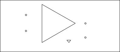
NI 621x devices implement the different analog input ground-reference settings by routing different signals to the NI-PGIA. The NI-PGIA is a differential amplifier. That is, the NI-PGIA amplifies (or attenuates) the difference in voltage between its two inputs. The NI-PGIA drives the ADC with this amplified voltage. The amount of amplification (the gain), is determined by the analog input range, as shown in Figure 4-2.
Instrumentation
Amplifier
Vin+ |
|
PGIA |
|
|
+ |
||
|
|
|
|||||
|
|
|
|
||||
|
|
|
|||||
Vin– |
|
|
|
|
Vm |
Measured |
|
|
|
||||||
|
Voltage |
||||||
|
|
|
|
|
|
|
|
|
|
|
|
|
|
|
– |
|
|
|
|
|
|
|
|
|
|
Vm = [Vin+ – Vin–] × Gain |
|
||||
Figure 4-2. NI-PGIA
Table 4-3 shows how signals are routed to the NI-PGIA.
Table 4-3. Signals Routed to the NI-PGIA
AI Ground-Reference |
Signals Routed to the Positive |
Signals Routed to the Negative |
Settings |
Input of the NI-PGIA (Vin+) |
Input of the NI-PGIA (Vin–) |
|
|
|
RSE |
AI <0..31> |
AI GND |
|
|
|
NRSE |
AI <0..31> |
AI SENSE |
|
|
|
DIFF |
AI <0..7> |
AI <8..15> |
|
|
|
|
AI <16..23> |
AI <24..31> |
|
|
|
For differential measurements, AI 0 and AI 8 are the positive and negative inputs of differential analog input channel 0. For a complete list of signal
NI USB-621x User Manual |
4-4 |
ni.com |
 Loading...