


 Loading...
USER GUIDE AND SPECIFICATIONS
NI cDAQ-9172
This user guide describes how to use the National Instruments cDAQ-9172 chassis and lists specifications. For an interactive demonstration of how to install the NI cDAQ-9172, go to ni.com/info and enter daqinstall.
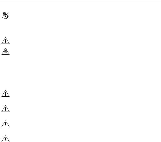
The NI cDAQ-9172 is an eight-slot USB chassis designed for use with C Series I/O modules. The NI cDAQ-9172 chassis is capable of measuring a broad range of analog and digital I/O and sensors using a Hi-Speed USB 2.0 interface. For module specifications, refer to the documentation included with your C Series I/O module(s) or go to ni.com/manuals.
1 |
|
|
|
|
|
NI cDAQ-9172 |
|
|
|
|
|
|
|
|
|
|
7 |
ON |
|
|
|
|
|
Ready |
1 |
2 |
3 |
4 |
5 |
2 |
|||||
Active |
|
|
|
|
|
OFF |
|
|
|
|
|
3 |
|
|
|
|
|
11-30 VDC |
|
|
|
|
|
15 W |
|
|
|
|
|
4 |
|
|
5 |
|
6 |
1 |
Power Switch |
5 |
Empty Module Slots |
2 |
Ready/Active LEDs |
6 |
Installed C Series I/O Modules |
3 |
Power Connector |
7 |
Screw for Ground Connection |
4 |
USB Connector |
|
|
|
|
|
|
Figure 1. NI cDAQ-9172
Safety Guidelines
Operate the NI cDAQ-9172 chassis only as described in this user guide.
Note Because some C Series I/O modules may have more stringent certification standards than the NI cDAQ-9172 chassis, the combined system may be limited by individual component restrictions. Refer to the Using the NI cDAQ-9172 section of this document for more details.
Caution The NI cDAQ-9172 chassis is not certified for use in hazardous locations.
Hot Surface This icon denotes that the component may be hot. Touching this component may result in bodily injury.
Safety Guidelines for Hazardous Voltages
If hazardous voltages are connected to the module, take the following precautions. A hazardous voltage is a voltage greater than 42.4 Vpk or 60 VDC to earth ground.
Caution Ensure that hazardous voltage wiring is performed only by qualified personnel adhering to local electrical standards.
Caution Do not mix hazardous voltage circuits and human-accessible circuits on the same module.
Caution Make sure that chassis and circuits connected to the module are properly insulated from human contact.
Caution The NI cDAQ-9172 chassis provides no isolation, but some modules offer isolation. Follow the safety guidelines for each module when using hazardous voltage.
NI cDAQ-9172 User Guide and Specifications |
2 |
ni.com |
Installing the NI cDAQ-9172
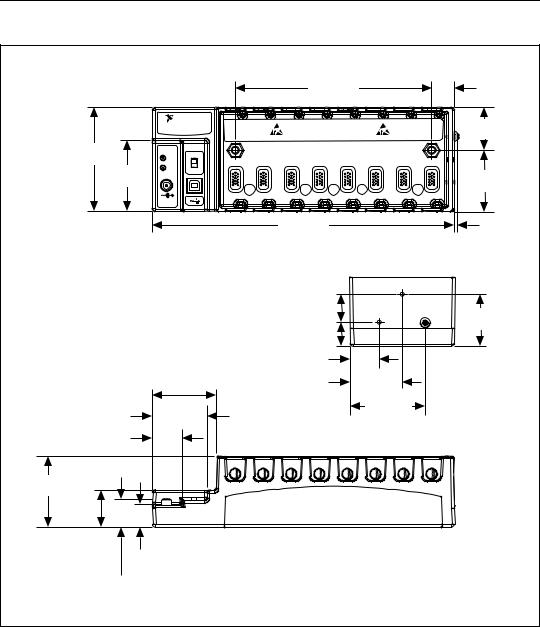
Figure 2 shows the dimensions of the NI cDAQ-9172 chassis.
|
|
|
|
|
165.1 mm |
|
|
19.0 mm |
|
|
|
|
|
|
(6.50 in.) |
|
|
(0.75 in.) |
|
|
NATIONAL |
|
|
|
|
|
|
|
|
|
INSTRUMENTS |
|
|
|
|
|
|
|
36.4 mm |
|
NI cDAQ-9172 |
|
|
|
|
|
|
|
|
|
|
|
|
|
|
|
|
|
(1.43 in.) |
88.1 mm |
|
|
|
|
|
|
|
|
|
(3.50 in.) |
ON |
|
|
|
|
|
|
|
|
Ready |
1 |
2 |
3 |
4 |
5 |
6 |
7 |
8 |
|
|
|||||||||
|
|
||||||||
59.6 mm |
Active |
|
|
|
|
|
|
|
|
OFF |
|
|
|
|
|
|
|
|
|
|
|
|
|
|
|
|
|
51.7 mm |
|
(2.35 in.) |
|
|
|
|
|
|
|
|
|
|
|
|
|
|
|
|
|
(2.04 in.) |
|
|
|
|
|
|
|
|
|
|
|
|
11-30 VDC |
|
|
|
|
|
|
|
|
|
15 W |
|
|
|
|
|
|
|
|
|
|
|
|
254.0 mm |
|
|
|
4.10 mm |
|
|
|
|
|
|
|
|
(0.16 in.) |
||
|
|
|
|
(10.00 in.) |
|
|
|
||
|
|
|
|
|
|
|
|
||
|
|
|
|
|
23.7 mm |
|
|
|
|
|
|
|
|
|
(0.94 in.) |
|
|
|
44.1 mm |
|
|
|
|
|
20.3 mm |
|
|
|
(1.74 in.) |
|
|
|
|
|
|
|
|
|
|
|
|
|
|
|
(0.80 in.) |
|
|
|
|
|
|
|
|
|
25.0 mm |
|
|
|
|
|
|
|
|
|
(0.98 in.) |
|
|
|
|
|
53.8 mm |
|
|
|
44.1 mm |
|
|
|
|
|
(2.12 in.) |
|
|
|
(1.74 in.) |
|
|
|
|
|
|
|
|
|
|
|
63.1 mm |
|
|
46.0 mm |
|
|
|
|
|
|
(2.49 in.) |
|
|
(1.81 in.) |
|
|
|
|
|
|
|
|
|
24.8 mm |
|
|
|
|
|
|
|
|
|
(0.98 in.) |
|
|
|
|
|
|
|
|
|
59.6 mm |
|
|
|
|
|
|
|
|
|
(2.35 in.) |
|
|
|
|
|
|
|
|
|
31.7 mm |
|
|
|
|
|
|
|
|
|
(1.25 in.) |
|
|
|
|
|
|
|
|
|
19.1 mm |
|
|
|
|
|
|
|
|
|
(0.75 in.) |
|
|
|
|
|
|
|
|
|
23.2 mm |
|
|
|
|
|
|
|
|
|
(0.91 in.) |
|
|
|
|
|
|
|
|
|
Figure 2. NI cDAQ-9172 with Dimensions in Millimeters (Inches)
© National Instruments Corporation |
3 |
NI cDAQ-9172 User Guide and Specifications |
Mounting the NI cDAQ-9172
You can mount the NI cDAQ-9172 chassis using a desktop, a 35 mm DIN-Rail, or a panel mount accessory kit. For accessory ordering information, refer to ni.com.
Caution Your installation must meet the following requirements:
•Allows 25.4 mm (1 in.) of clearance above and below the NI cDAQ-9172 chassis for air circulation.
•Allows 50.8 mm (2 in.) of clearance in front of modules for common connector cabling, such as the 10-terminal detachable screw terminal connector.
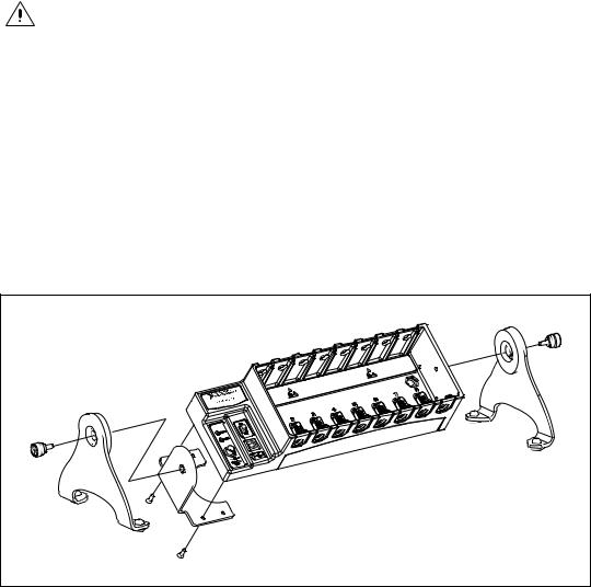
NI 9901 Desktop Mounting Kit
The NI 9901 Desktop Mounting Kit includes two metal feet you can install on the sides of the NI cDAQ-9172 chassis for desktop use. With this kit, you can tilt the NI cDAQ-9172 chassis for convenient access to the I/O module connectors. When you put on the two metal feet, the two existing screws on the power switch side of the chassis must be removed. After removing the screws, replace them with the two longer screws included in the NI 9901 Desktop Mounting Kit.
Figure 3. NI 9901 Desktop Mounting Kit
NI cDAQ-9172 User Guide and Specifications |
4 |
ni.com |
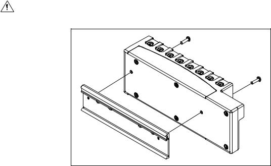
Mounting the NI 9910 DIN-Rail Kit
The NI 9910 DIN-Rail kit contains one clip for mounting the chassis on a standard 35 mm DIN-Rail. To mount the chassis on a DIN-Rail, fasten the DIN-Rail clip to the chassis using a number 2 Phillips screwdriver and two M4 × 16 screws. The screws are included in the DIN-Rail kit. Make sure the DIN-Rail kit is installed as illustrated in Figure 4, with the larger lip of the DIN-RAIL positioned up. When the DIN-Rail kit is properly installed, the NI cDAQ-9172 chassis is centered on the DIN-Rail.
Caution Remove the I/O modules before removing the chassis from the DIN-Rail.
Figure 4. DIN-Rail Dimensions and Installation on the NI cDAQ-9172
Mounting the NI 9905 Panel Mount Kit
To mount the chassis on a panel, align the chassis on the panel mount accessory. Attach the chassis to the panel mount kit using two M4 × 16 screws (as pictured in the following diagram). National Instruments provides these screws with the panel mount kit. You must use these screws because they are the correct depth and thread for the panel. These slots in the panel mount kit can be used with M4, M5, No. 8, or No.10 panhead
© National Instruments Corporation |
5 |
NI cDAQ-9172 User Guide and Specifications |
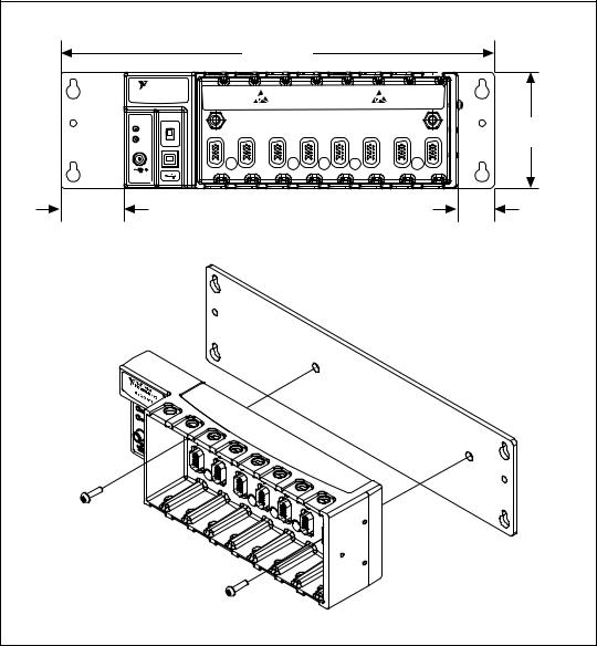
screws. Figure 5 illustrates the panel dimensions and installation on the NI cDAQ-9172 chassis. Refer to the documentation included with the NI 9905 shipping kit for more detailed dimensions.
|
|
330.2 mm |
|
|
|
|
|
|
|
|
(13.00 in.) |
|
|
|
|
|
|
NATIONAL |
|
|
|
|
|
|
|
|
INSTRUMENTS |
|
|
|
|
|
|
|
|
NI cDAQ-9172 |
|
|
|
|
|
|
|
|
ON |
|
|
|
|
|
|
|
88.1 mm |
Ready |
2 |
3 |
4 |
5 |
6 |
7 |
8 |
|
1 |
(3.47 in.) |
|||||||
Active |
|
|
|
|
|
|
|
|
OFF |
|
|
|
|
|
|
|
|
|
|
|
|
|
|
|
|
|
11-30 VDC |
|
|
|
|
|
|
|
|
15 W |
|
|
|
|
|
|
|
|
48.1 mm |
|
|
|
|
|
28.1 mm |
|
|
(1.90 in.) |
|
|
|
|
|
(1.11 in.) |
|
|
Figure 5. Panel Mount Dimensions and Installation on the NI cDAQ-9172
NI cDAQ-9172 User Guide and Specifications |
6 |
ni.com |
Setting Up the NI cDAQ-9172
Complete the following steps to prepare the NI cDAQ-9172 chassis for use:
1.Before connecting the hardware, install NI-DAQmx software,
VI Logger, and the NI-DAQ Device Documentation Browser. Refer to the DAQ Getting Started Guide for more information about software installation.
Note The NI-DAQmx software is included on the CD shipped with your kit and is available for download at ni.com/support. After you install it, the NI-DAQ Device Documentation Browser is available from Start»Programs»National Instruments» NI-DAQ»Browse Device Documentation. The DAQ Getting Started Guide is available after installation from Start»Programs»National Instruments»NI-DAQ»DAQ Getting Started Guide.
2.If you are not using any mounting accessories, attach the provided rubber standoffs to the back of the NI cDAQ-9172 chassis.
3.Make sure the NI cDAQ-9172 chassis power switch is turned off.
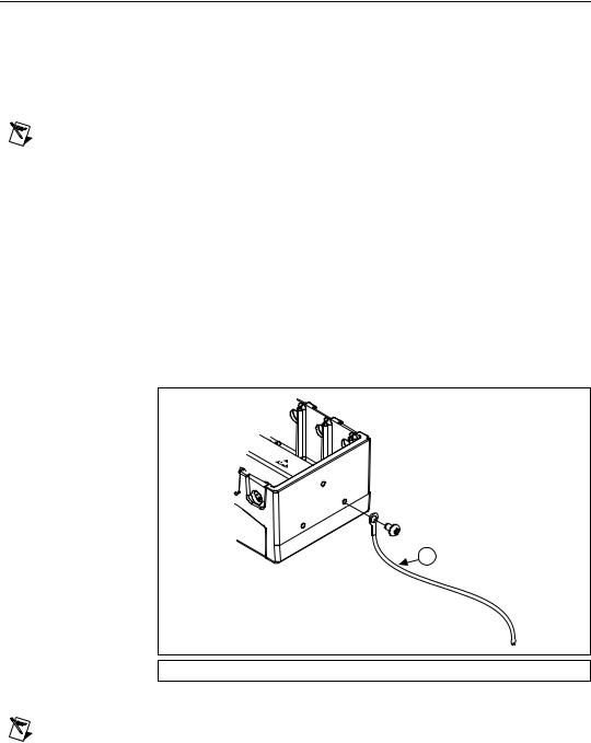
4.Attach a ring lug to a 14 AWG (1.6 mm) wire. Connect the ring lug to the ground terminal on the side of the chassis using the ground screw. Attach the other end of the wire to the system safety ground.
1
1 Attached to System Ground
Figure 6. Ring Lug Attached to Ground Terminal
Note Additionally, attach a wire with a ring lug to all other C Series I/O module cable shields. You must connect this wire to the ground terminal of the chassis using the ground screw.
© National Instruments Corporation |
7 |
NI cDAQ-9172 User Guide and Specifications |
5.Remove the plastic cover from the connector in any empty module slot.
6.Squeeze both C Series I/O module latches, insert the I/O module into the module slot, and press until both latches lock the module in place.
7.Connect the NI cDAQ-9172 chassis with the supplied USB cable to any available USB port on your computer.
8.Connect the power source to the NI cDAQ-9172 chassis. The
NI cDAQ-9172 chassis requires an external power supply that meets the specifications in the Power Requirements section.
Note The NI cDAQ-9172 chassis uses a DC input jack with a locking ring. Use only this connector with the NI cDAQ-9172 chassis. Refer to the Specifications section for more information about the connector.
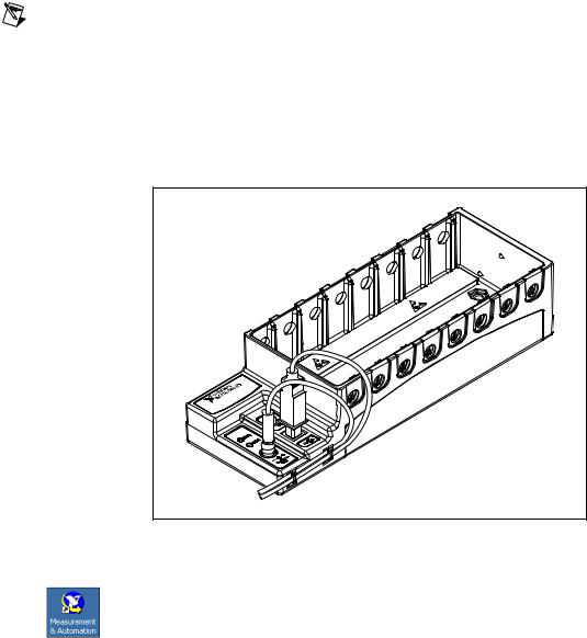
9.Secure the power supply and USB cables, as depicted in Figure 7, using the two tie wraps and adhesive tie wrap mounts included in the shipping kit. The tie wraps and adhesive mounts help secure the non-latching USB connection. They can also be used to route the cables to a desirable position.
-9172 |
cDAQ |
NI |
Figure 7. cDAQ Chassis With Secured Cables
10.Power on the NI cDAQ-9172 chassis.
11.Double-click the Measurement & Automation icon, shown at left, on the desktop to open MAX.
NI cDAQ-9172 User Guide and Specifications |
8 |
ni.com |

12.Expand Devices and Interfaces, and then expand NI-DAQmx Devices.
13.Check that your device appears under Devices and Interfaces. If your device does not appear, press <F5> to refresh the view in MAX. If your device is still not recognized, refer to ni.com/support/install for troubleshooting information.
14.Right-click your device and select Self-Test.
If you need help during the self-test, select Help»Help Topics» NI-DAQmx and click MAX Help for NI-DAQmx.
When the self-test finishes, a message indicates successful verification or an error. If an error occurs, refer to ni.com/support/install for troubleshooting information.
Note When in use, the NI cDAQ-9172 chassis may become warm to the touch. This is normal.
Understanding LED Indications
Active LED
The Active LED indicates whether the NI cDAQ-9172 chassis is communicating over the USB bus.
|
Table 1. Active LED |
|
|
LED |
Definition |
|
|
|
|
Amber |
Power is applied, but USB connection is not |
|
established |
|
|
Green |
USB traffic present |
|
|
Off |
No USB traffic present |
|
|
Ready LED
The Ready LED is lit when the NI cDAQ-9172 chassis is ready for use. The color indicates whether the USB connection is Full-Speed or Hi-Speed.
|
Table 2. Ready LED |
|
|
LED |
Definition |
|
|
|
|
Amber |
Hi-Speed (480 Mbit/sec) |
|
|
© National Instruments Corporation |
9 |
NI cDAQ-9172 User Guide and Specifications |
|
Table 2. Ready LED (Continued) |
|
|
|
|
LED |
|
Definition |
|
|
|
|
|
|
Green |
|
Full-Speed (12 Mbit/sec) |
|
|
|
Off |
|
USB connection is not established |
|
|
|
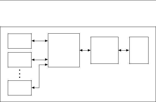
Using the NI cDAQ-9172
The cDAQ system consists of three parts: C Series I/O modules, the cDAQ module interface, and the USB-STC2. These components digitize signals, perform D/A conversions to generate analog output signals, measure and control digital I/O signals, and provide signal conditioning.
C Series |
|
|
I/O Module |
|
|
cDAQ Module |
USB- |
USB |
Interface |
STC2 |
2.0 |
C Series |
|
|
I/O Module |
|
|
C Series |
|
|
I/O Module |
|
|
Figure 8. NI cDAQ-9172 Block Diagram
C Series I/0 Modules
National Instruments C Series I/O modules provide built-in signal conditioning and screw terminal, spring terminal, BNC, D-SUB, or RJ-50 connectors. A wide variety of I/O types are available, allowing you to customize the cDAQ system to meet your application needs.
C Series I/O modules are hot-swappable and automatically detected by the NI cDAQ-9172 chassis. I/O channels are accessible using the NI-DAQmx driver software.
Because the modules contain built-in signal conditioning for extended voltage ranges or industrial signal types, you can usually make your
NI cDAQ-9172 User Guide and Specifications |
10 |
ni.com |
wiring connections directly from the C Series I/O modules to your sensors/actuators. In most cases, the C Series I/O modules provide isolation from channel-to-earth ground.
For more information about which C Series I/O modules are compatible with the NI cDAQ-9172 chassis, refer to the KnowledgeBase document,
C Series Modules Supported in the NI cDAQ-9172. To access this KnowledgeBase, go to ni.com/info and enter the info code rdcdaq.
Correlated vs. Static DIO Modules
Digital I/O module capabilities are determined by the type of digital signals that the module is capable of measuring or generating. Static Digital I/O modules are designed for signals that change slowly and are accessed
by software-timed reads and writes. Correlated Digital I/O modules are for signals that change rapidly and are updated by either software or hardware-timed reads and writes. Correlated Digital I/O modules can perform the following tasks:
•Used in any slot—software-timed reads and writes.
•Used in slots 1 though 4—Digital Waveform Generation and Acquisition (Correlated Input/Output)
•Used in slots 5 and 6—Counter/Timer
•Used in slots 5 and 6—Access PFI signals
To determine the capability of digital I/O modules supported by the
NI cDAQ-9172 chassis, refer to the KnowledgeBase document, C Series Modules Supported in the NI cDAQ-9172. To access this KnowledgeBase document, go to ni.com/info and enter the info code rdcdaq.
cDAQ Module Interface
The cDAQ Module Interface manages data transfers between the USB-STC2 and the C Series I/O modules. The interface also handles autodetection, signal routing, and synchronization.
USB-STC2
The USB-STC2 features independent High-Speed data streams; flexible AI and AO sample timing; triggering; PFI signals for multi-device synchronization; flexible counter/timers with hardware gating; digital waveform acquisition and generation; and static DIO.
AI and AO Sample Timing
The USB-STC2 contains advanced analog input and analog output timing engines. A wide range of timing and synchronization signals are available
© National Instruments Corporation |
11 |
NI cDAQ-9172 User Guide and Specifications |

through the PFI lines. Refer to the Analog Input Timing Signals and Analog Output Timing Signals sections for more information about the configuration of these signals.
Triggering Modes
The NI cDAQ-9172 supports different trigger modes, such as start trigger, reference trigger, and pause trigger with analog, digital, or software sources. Refer to the Analog Input Triggering and Analog Output Triggering sections for more information.
Independent Data Streams
The NI cDAQ-9172 supports four independent high-speed data streams; allowing for up to four simultaneous hardware timed tasks, such as analog input, analog output, buffered counter/timers, and correlated digital input/output.
PFI Signals
The PFI signals, available through correlated digital input and output modules installed in slots 5 and 6, provide access to advanced features such as triggering, synchronization, and counter/timers. Refer to the PFI section for more information.
The PFI pins have a digital filter circuit at the inputs that is configurable on a per-line basis. The filters allow the rejection of noise caused by noisy environments, bounces on switches, and so on.
Flexible Counter/Timers
The NI cDAQ-9172 includes two general-purpose 32-bit counter/timers that can be used to count edges, measure pulse-widths, measure periods and frequencies, and perform position measurements (encoding). In addition, the counter/timers can generate pulses, pulse trains, and square waves with adjustable frequencies. You can access the counter inputs and outputs using correlated digital I/O modules in slots 5 and/or 6. Refer to the Counters section for more information.
Analog Input
To perform analog input measurements, insert a supported analog input C Series I/O module into any slot on the cDAQ chassis. The measurement specifications, such as number of channels, channel configuration, sample rate, and gain, are determined by the type of C Series I/O module used. For more information and wiring diagrams, refer to the documentation included with your C Series I/O modules.
NI cDAQ-9172 User Guide and Specifications |
12 |
ni.com |
The NI cDAQ-9172 has one AI timing engine, which means that only one analog input task may be running at a time on a chassis. However, the analog input task can include channels from multiple analog input modules.
Analog Input Triggering
A trigger is a signal that causes an action, such as starting or stopping the acquisition of data. When you configure a trigger, you must decide how you want to produce the trigger and the action you want the trigger to cause. The NI cDAQ-9172 chassis supports internal software triggering, external digital, and analog triggering.
Three triggers are available: start trigger, reference trigger, and pause trigger. An analog or digital trigger can initiate these three trigger actions. Any C Series correlated digital input module can supply a digital trigger when installed in slots 5 or 6, and some C Series analog modules can supply an analog or digital trigger in any slot. The start, reference, and pause triggers can come from three separate modules if desired. To find your module triggering options, refer to the documentation included with your C Series I/O modules. For more information about using digital modules for triggering, refer to the Digital I/O section.
AI Start Trigger Signal
Use the AI Start Trigger (ai/StartTrigger) signal to begin a measurement acquisition. A measurement acquisition consists of one or more samples. If you do not use triggers, begin a measurement with a software command. Once the acquisition begins, configure the acquisition to stop in one of the following ways:
•When a certain number of points is sampled (in finite mode)
•After a hardware reference trigger (in finite mode)
•With a software command (in continuous mode)
An acquisition that uses a start trigger (but not a reference trigger) is sometimes referred to as a posttriggered acquisition. That is, samples are measured only after the trigger.
When you are using an internal sample clock, you can specify a delay from the start trigger to the first sample.
Using a Digital Source
To use ai/StartTrigger with a digital source, specify a source and an edge.
Use the following signals as the source:
•Any PFI terminal
•Counter n Internal Output
© National Instruments Corporation |
13 |
NI cDAQ-9172 User Guide and Specifications |
The source also can be one of several other internal signals on your NI cDAQ-9172 chassis. Refer to Device Routing in MAX in the NI-DAQmx Help or the LabVIEW Help in version 8.0 or later for more information.
The NI-DAQmx Help is available after installation from Start»Programs» National Instruments»NI-DAQ»NI-DAQmx Help. To view the
LabVIEW Help, in version 8.0 or later, select Help»Search the LabVIEW Help in LabVIEW. Alternately, to download the LabVIEW Help, go to ni.com/manuals.
You also can specify whether the measurement acquisition begins on the rising edge or falling edge of ai/StartTrigger.
Using an Analog Source
Some C Series I/O modules can generate a trigger based on an analog signal. In NI-DAQmx, this is called the Analog Comparison Event. When you use an analog trigger source for ai/StartTrigger, the acquisition begins on the first rising or falling edge of the Analog Comparison Event signal, depending on the trigger properties.
Routing AI Start Trigger to an Output Terminal
You can route ai/StartTrigger to any output PFI terminal. The output is an active high pulse.
AI Reference Trigger Signal
Use a reference trigger (ai/ReferenceTrigger) signal to stop a measurement acquisition. To use a reference trigger, specify a buffer of finite size and a number of pretrigger samples (samples that occur before the reference trigger). The number of posttrigger samples (samples that occur after the reference trigger) desired is the buffer size minus the number of pretrigger samples.
When the acquisition begins, the NI cDAQ-9172 chassis begins to fill the buffer. After the specified number of pretrigger samples are captured, the NI cDAQ-9172 begins to look for the reference trigger condition. If the reference trigger condition occurs before the NI cDAQ-9172 captures the specified number of pretrigger samples, the NI cDAQ-9172 ignores the condition.
If the buffer becomes full, the NI cDAQ-9172 continuously discards the oldest samples in the buffer to make space for the next sample. This data can be accessed (with some limitations) before the NI cDAQ-9172 discards it. Refer to the KnowledgeBase document, Can a Pretriggered Acquisition
NI cDAQ-9172 User Guide and Specifications |
14 |
ni.com |
be Continuous?, for more information. To access this KnowledgeBase, go to ni.com/info and enter the info code rdcanq.
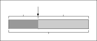
When the reference trigger occurs, the NI cDAQ-9172 continues to write samples to the buffer until the buffer contains the number of posttrigger samples desired. Figure 9 shows the final buffer.
Reference Trigger |
|
Pretrigger Samples |
Posttrigger Samples |
|
Complete Buffer |
Figure 9. Reference Trigger Final Buffer
Using a Digital Source
To use ai/ReferenceTrigger with a digital source, specify a source and an edge. Either PFI or one of several internal signals on the NI cDAQ-9172 chassis can provide the source. Refer to Device Routing in MAX in the NI-DAQmx Help or the LabVIEW Help in version 8.0 or later for more information.
The NI-DAQmx Help is available after installation from Start»Programs» National Instruments»NI-DAQ»NI-DAQmx Help. To view the
LabVIEW Help, in version 8.0 or later, select Help»Search the LabVIEW Help in LabVIEW. Alternately, to download the LabVIEW Help, go to ni.com/manuals.
You also can specify whether the measurement acquisition stops on the rising edge or falling edge of ai/ReferenceTrigger.
Using an Analog Source
Some C Series I/O modules can generate a trigger based on an analog signal. In NI-DAQmx, this is called the Analog Comparison Event.
When you use an analog trigger source, the acquisition stops on the first rising or falling edge of the Analog Comparison Event signal, depending on the trigger properties.
© National Instruments Corporation |
15 |
NI cDAQ-9172 User Guide and Specifications |

Routing AI Reference Trigger Signal to an Output Terminal
You can route ai/ReferenceTrigger to any output PFI terminal.
AI Pause Trigger Signal
The Pause Trigger signal can be generated from internal or external sources. Any time the signal deasserts, you can use the Pause Trigger signal to pause the acquisition.
You can use the AI Pause Trigger (ai/PauseTrigger) signal to pause and resume a measurement acquisition. The internal sample clock pauses while the external trigger signal is active and resumes when the signal is inactive. You can program the active level of the pause trigger to be high or low.
Using a Digital Source
To use ai/PauseTrigger, specify a source and a polarity. The source can be either from PFI or one of several other internal signals on your NI cDAQ-9172 chassis. Refer to Device Routing in MAX in the NI-DAQmx Help or the LabVIEW Help in version 8.0 or later for more information.
The NI-DAQmx Help is available after installation from Start»Programs» National Instruments»NI-DAQ»NI-DAQmx Help. To view the
LabVIEW Help, in version 8.0 or later, select Help»Search the LabVIEW Help in LabVIEW. Alternately, to download the LabVIEW Help, go to ni.com/manuals.
Using an Analog Source
Some C Series I/O modules can generate a trigger based on an analog signal. In NI-DAQmx, this is called the Analog Comparison Event.
When you use an analog trigger source, the internal sample clock pauses when the Analog Comparison Event signal is low and resumes when the signal goes high (or vice versa).
Note Pause triggers are only sensitive to the level of the source, not the edge.
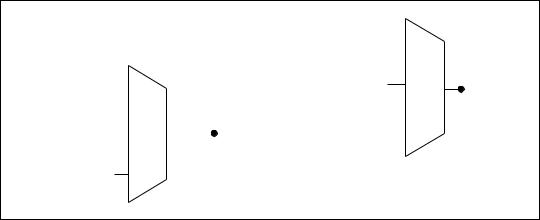
Analog Input Timing Signals
AI Sample Clock
A sample consists of one reading from each channel in the AI task. ai/SampleClock signals the start of a sample of all analog input channels in the task. ai/SampleClock can be generated from external or internal sources.
NI cDAQ-9172 User Guide and Specifications |
16 |
ni.com |
|
|
|
|
|
PFI |
|
|
|
|||
|
|
|
|
|
|
||||||
|
|
|
|
Analog Comparison Event |
|
|
|
||||
|
|
|
|
|
|
||||||
|
|
|
|
|
Ctr n Internal Output |
|
|
||||
|
|
|
|
|
|||||||
|
|
|
|
|
|
|
|
|
|
|
ai/SampleClock |
PFI |
|
|
Sigma-Delta Module Internal Output |
||||||||
|
|
ai/SampleClock |
|
|
|
|
|
|
|
|
|
|
|
|
|
|
|
|
|
|
|
||
Analog Comparison |
|
|
|
|
|
|
|
|
|
|
|
|
|
Timebase |
|
Programmable |
|
|
|
|
|
|
|
Event |
|
|
|
|
|||||||
|
|
|
|
Clock |
|
|
|
|
|
|
|
|
|
|
|
|
|
|
|
|
|
|
|
20 MHz Timebase |
|
|
|
|
Divider |
|
|||||
|
|
|
|||||||||
|
|
|
|
|
|
|
|
|
|
|
|
100 kHz Timebase
Figure 10. Sample Clock Timing Options
Routing AI Sample Clock to an Output Terminal
You can route ai/SampleClock to any output PFI terminal.
AI Sample Clock Timebase
The AI Sample Clock Timebase (ai/SampleClockTimebase) signal is divided down to provide a source for ai/SampleClock. ai/SampleClock Timebase can be generated from external or internal sources. ai/SampleClockTimebase is not available as an output from the chassis.
Convert Behavior For Analog Input Modules
Scanned
Scanned C Series analog input modules contain a single A/D converter and a multiplexer to select between multiple input channels. When the cDAQ Module Interface receives a Sample Clock pulse, it begins generating a Convert Clock for each scanned module in the current task. Each Convert Clock signals the acquisition of a single channel from that module. The Convert Clock rate depends on the module being used, the number of channels used on that module, and the system Sample Clock rate.
The driver chooses the fastest conversion rate possible based on the speed of the A/D converter for each module and adds 10 µs of padding between each channel to allow for adequate settling time. This scheme enables the channels to approximate simultaneous sampling. If the AI Sample Clock rate is too fast to allow for 10 µs of padding, NI-DAQmx selects a conversion rate that spaces the AI Convert Clock pulses evenly throughout the sample. NI-DAQmx uses the same amount of padding for all the modules in the task. To explicitly specify the conversion rate, use the
© National Instruments Corporation |
17 |
NI cDAQ-9172 User Guide and Specifications |
ActiveDevs and AI Convert Clock Rate properties using the DAQmx Timing property node or functions.
Simultaneous Sample-and-Hold
Simultaneous sample-and-hold (SSH) C Series analog input modules contain multiple A/D converters or circuitry that allows all the input channels to be sampled at the same time. These modules sample their inputs on every Sample Clock pulse.
Sigma-Delta
Sigma-delta C Series analog input modules function much like SSH modules, but use A/D converters that require a high-frequency oversample clock to produce accurate, synchronized data. Sigma-delta modules in the cDAQ chassis automatically share a single oversample clock to synchronize data from all sigma-delta modules.
This clock is used as the AI Sample Clock Timebase. While most modules supply a common oversample clock frequency (12.8 MHz), some modules, like the NI 9234, supply a different frequency. When sigma-delta modules with different oversample clock frequencies are used in an analog
input task, the AI Sample Clock Timebase can use any of the available frequencies; by default, the fastest available is used. The sampling rate of all modules in the system is an integer divisor of the frequency of the AI Sample Clock Timebase.
When one or more sigma-delta modules are in an analog input task, the sigma-delta modules also provide the signal used as the AI Sample Clock. This signal is used to cause A/D conversion for other modules in the system, just as the AI Sample Clock does when a sigma-delta module is not being used.
When sigma-delta modules are in an AI task, the chassis automatically issues a synchronization pulse to each sigma-delta modules that resets their ADCs at the same time. Both the synchronization pulse and the oversample clock can be routed from or to any PFI line to allow synchronization between multiple chassis. Because of the filtering used in sigma-delta A/D converters, these modules usually exhibit a fixed input delay relative to non-sigma-delta modules in the system. This input delay is specified in the C Series I/O module documentation.
Slow Sample Rate Modules
Some C Series analog input modules are specifically designed for measuring signals that vary slowly, such as temperature. Because of their slow rate, it is not appropriate for these modules to constrain the AI Sample Clock to operate at or slower than their maximum rate. When using such a
NI cDAQ-9172 User Guide and Specifications |
18 |
ni.com |
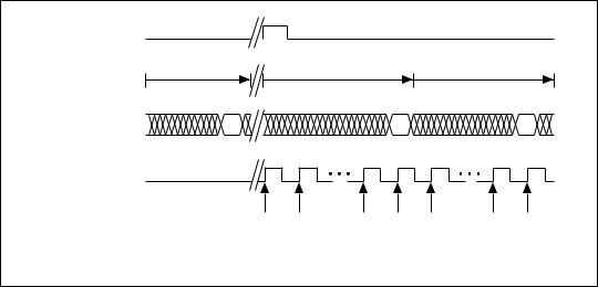
module in the cDAQ chassis, the maximum Sample Clock rate can run faster than the maximum rate for the module. When operating at a rate faster than these slow rate modules can support, the slow rate module returns the same point repeatedly, until a new conversion completes. The first point is acquired when the task is committed. The second point is acquired after the start trigger.
ai/StartTrigger
|
1st A/D Conversion |
2nd A/D Conversion |
|
|
3rd A/D Conversion |
|
|
Data from |
|
|
|
|
|
|
|
A/D Conversion |
A |
|
|
B |
|
|
C |
(Slow Module) |
|
|
|
|
|
|
|
ai/SampleClock |
|
|
|
|
|
|
|
Data Returned |
A |
A |
A |
B |
B |
B |
C |
|
|||||||
to AI Task
Figure 11. Sample Clock Timing Example
For example, if running an AI task at 1 kHz using a module with a maximum rate of 10 Hz, the slow module returns 100 samples of the first point, followed by 100 samples of the second point, etc. Other modules in the task will return 1,000 new data points per second, which is normal. When performing a single-point acquisition, no points are repeated.
Refer to the KnowledgeBase document, C Series Modules Supported in the NI cDAQ-9172, for more information. To access this KnowledgeBase,
go to ni.com/info and enter the info code rdcdaq.
Getting Started with AI Applications in Software
You can use the NI cDAQ-9172 chassis in the following analog input applications:
•Single-Point
•Finite
•Continuous
© National Instruments Corporation |
19 |
NI cDAQ-9172 User Guide and Specifications |

For more information about programming analog input applications and triggers in software, Refer to the NI-DAQmx Help or the LabVIEW Help in version 8.0 or later for more information.
The NI-DAQmx Help is available after installation from Start»Programs» National Instruments»NI-DAQ»NI-DAQmx Help. To view the
LabVIEW Help, in version 8.0 or later, select Help»Search the LabVIEW Help in LabVIEW. Alternately, to download the LabVIEW Help, go to ni.com/manuals.
Analog Output
To generate analog output, insert an analog output C Series I/O module in any slot on the NI cDAQ-9172 chassis. The generation specifications, such as the number of channels, channel configuration, update rate, and output range, are determined by the type of C Series I/O module used. For more information, refer to the documentation included with your C Series I/O modules.
You can run one hardware-timed (waveform) analog output task at a time on the NI cDAQ-9172 chassis, with up to 16 waveform channels. At the same time, you can also run one or more software-timed (single-point or immediate) tasks.
For each analog output module, you can either:
•Assign all of the channels on the module to the hardware-timed task.
•Assign all of the channels on the module to one or more software-timed tasks.
On a single AO module, you cannot assign some channels to a hardware-timed task and other channels (on the same module) to a software-timed task.
Analog Output Data Generation Methods
When performing an analog output operation, you either can perform software-timed or hardware-timed generations. Hardware-timed generations must be buffered.
Software-Timed Generations
With a software-timed generation, software controls the rate at which data is generated. Software sends a separate command to the hardware to initiate each DAC conversion. In NI-DAQmx, software-timed generations are referred to as on-demand timing. Software-timed generations are also
NI cDAQ-9172 User Guide and Specifications |
20 |
ni.com |
referred to as immediate or static operations. They are typically used for writing out a single value, such as a constant DC voltage.
The following considerations apply to software-timed generations:
•If any AO channel on a module is used in a hardware-timed (waveform) task, no channels on that module can be used in a software-timed task.
•You can configure software-timed generation to simultaneously update.
•Only one simultaneous update task can run at a time.
•Simultaneous update is not restricted to 16 channels.
•A hardware-timed AO task and a simultaneous update AO task cannot run at the same time.
Hardware-Timed Generations
With a hardware-timed generation, a digital hardware signal controls the rate of the generation. This signal can be generated internally on the chassis or provided externally.
Hardware-timed generations have several advantages over software-timed acquisitions:
•The time between samples can be much shorter.
•The timing between samples is deterministic.
•Hardware-timed acquisitions can use hardware triggering.
Hardware-timed AO operations on the NI cDAQ-9172 chassis must be buffered.
Buffered Analog Output
A buffer is a temporary storage in computer memory for generated samples. In a buffered generation, data is moved from a host buffer to the NI cDAQ-9172 onboard FIFO before it is written to the C Series I/O modules.
One property of buffered I/O operations is sample mode. The sample mode can be either finite or continuous.
Finite sample mode generation refers to the generation of a specific, predetermined number of data samples. Once the specified number of samples is written out, the generation stops.
Continuous generation refers to the generation of an unspecified number of samples. Instead of generating a set number of data samples and stopping,
© National Instruments Corporation |
21 |
NI cDAQ-9172 User Guide and Specifications |
a continuous generation continues until you stop the operation. There are three different continuous generation modes that control how the data
is written. These modes are regeneration, onboard regeneration, and non-regeneration.
In regeneration mode, you define a buffer in host memory. The data from the buffer is continually downloaded to the FIFO to be written out. New data can be written to the host buffer at any time without disrupting the output.
With onboard regeneration, the entire buffer is downloaded to the FIFO and regenerated from there. After the data is downloaded, new data cannot be written to the FIFO. To use onboard regeneration, the entire buffer must fit within the FIFO size. The advantage of using onboard regeneration is that it does not require communication with the main host memory once the operation is started, which prevents problems that may occur due to excessive bus traffic or operating system latency.
With non-regeneration, old data is not repeated. New data must continually be written to the buffer. If the program does not write new data to the buffer at a fast enough rate to keep up with the generation, the buffer underflows and causes an error.
Analog Output Triggering
Analog output supports two different triggering actions:
•Start trigger
•Pause trigger
An analog or digital trigger can initiate these actions. Any C Series correlated digital module in slots 5 and/or 6 can supply a digital trigger, and some C Series analog modules can supply an analog trigger. For more information refer to the AO Start Trigger Signal section of this document or to the documentation included with your C Series I/O module(s).
Analog Output Timing Signals
The NI cDAQ-9172 chassis features the following AO (waveform generation) timing signals:
•AO Sample Clock
•AO Start Trigger
•AO Pause Trigger
NI cDAQ-9172 User Guide and Specifications |
22 |
ni.com |
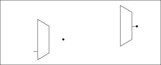
AO Sample Clock
The AO sample clock signals when all the analog output channels in the task update. ao/SampleClock can be generated from external or internal sources.
|
|
|
|
|
|
PFI |
|
|
|
|
|
|
|
Analog Comparison Event |
|
|
ao/SampleClock |
||
|
|
|
|
|
|||||
|
|
|
|
|
|
|
|
|
|
PFI |
|
|
ao/SampleClock |
|
Ctr n Internal Output |
|
|
|
|
|
|
|
|
||||||
|
|
|
|
|
|
|
|
||
Analog Comparison |
|
|
|
|
|
|
|
|
|
|
|
Timebase |
|
Programmable |
|
|
|
|
|
Event |
|
|
|
|
|
||||
|
|
|
|
Clock |
|
|
|
|
|
|
|
|
|
|
|
|
|
|
|
20 MHz Timebase |
|
|
|
|
Divider |
|
|
||
|
|
|
|
||||||
|
|
|
|
|
|
|
|
|
|
100 kHz Timebase
Figure 12. Analog Output Timing Options
Routing AO Sample Clock to an Output Terminal
You can route ao/SampleClock to any output PFI terminal.
AO Sample Clock Timebase
The AO Sample Clock Timebase (ao/SampleClockTimebase) signal is divided down to provide a source for ao/SampleClock. ao/SampleClockTimebase can be generated from external or internal sources, and is not available as an output from the chassis.
AO Start Trigger Signal
Use the AO Start Trigger (ao/StartTrigger) signal to initiate a waveform generation. If you do not use triggers, you can begin a generation
with a software command. If you are using an internal sample clock, you can specify a delay from the start trigger to the first sample. For more information, refer to the NI-DAQmx Help. The NI-DAQmx Help is
available after installation from Start»Programs»National Instruments» NI-DAQ»NI-DAQmx Help.
© National Instruments Corporation |
23 |
NI cDAQ-9172 User Guide and Specifications |
Loading...