


OPERATING INSTRUCTIONS AND SPECIFICATIONS
NI 9871
4-Port, RS485/RS422 Serial Module

This document describes how to use the National Instruments 9871 and includes specifications and pin assignments for the NI 9871. Visit ni.com/info and enter rdsoftwareversion to determine which software you need for the modules you are using. For information about installing, configuring, and programming the system, refer to the system documentation. Visit ni.com/info and enter cseriesdoc for information about C Series documentation.
Note The safety guidelines and specifications in this document are specific to the NI 9871. The other components in the system might not meet the same safety ratings and specifications. Refer to the documentation for each component in the system to determine the safety ratings and specifications for the entire system. Visit ni.com/info and enter cseriesdoc for information about C Series documentation.
Safety Guidelines
Operate the NI 9871 only as described in these operating instructions.
Hot Surface This icon denotes that the component may be hot. Touching this component may result in bodily injury.
NI 9871 Operating Instructions |
2 |
ni.com |

Safety Guidelines for Hazardous Locations
The NI 9871 is suitable for use in Class I, Division 2, Groups A, B, C, D, T4 hazardous locations; Class I, Zone 2, AEx nA II T4 and Ex nA II T4 hazardous locations; and nonhazardous locations only. Follow these guidelines if you are installing the NI 9871 in a potentially explosive environment. Not following these guidelines may result in serious injury or death.
Caution Do not disconnect I/O-side wires or connectors unless power has been switched off or the area is known to be nonhazardous.
Caution Do not remove modules unless power has been switched off or the area is known to be nonhazardous.
Caution Substitution of components may impair suitability for Class I, Division 2.
Caution For Zone 2 applications, install the CompactRIO system in an enclosure rated to at least IP 54 as defined by IEC 60529 and EN 60529.
© National Instruments Corp. |
3 |
NI 9871 Operating Instructions |

Caution For Zone 2 applications, install a protection device between the RS485/RS422 signal cables and the NI 9871 RJ-50 jacks (ports 1–4). The device must prevent the RS485/RS422 signal-to-signal or signal-to-COM voltage from exceeding 23 V if there is a transient overvoltage condition.
Caution For Zone 2 applications, install a protection device between the external power supply and the
NI 9871 Vsup and COM pins. The device must prevent the Vsup-to-COM voltage from exceeding 39 V if there is a
transient overvoltage condition.
Special Conditions for Hazardous Locations in Europe
This equipment has been evaluated as Ex nA IIC T4 equipment under DEMKO Certificate No. 07 ATEX 0626664X. Each module is marked  II 3G and is suitable for use in Zone 2 hazardous locations. If you are using the NI 9871 in Gas Group IIC hazardous locations or in ambient temperatures of –40 °C ≤ Ta ≤ 70 °C, you must use the device in an NI chassis or controller that has been evaluated as EEx nC IIC T4, Ex nA IIC T4, or Ex nL IIC T4 equipment.
NI 9871 Operating Instructions |
4 |
ni.com |

Special Conditions for Marine Applications
Some modules are Lloyd’s Register (LR) Type Approved for marine applications. To verify Lloyd’s Register certification, visit ni.com/certification and search for the LR certificate, or look for the Lloyd’s Register mark on the module.
Caution To meet radio frequency emission requirements for marine applications, use shielded cables and install the system in a metal enclosure. Suppression ferrites must be installed on power supply inputs near power entries to modules and controllers. Power supply and module cables must be separated on opposite sides of the enclosure and must enter and exit through opposing enclosure walls.
© National Instruments Corp. |
5 |
NI 9871 Operating Instructions |
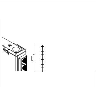
Wiring the NI 9871
The NI 9871 has four RJ-50 receptacles that provide connections for four RS485/RS422 devices.
Table 1. RS485/RS422 Port Pinout
|
|
|
|
|
|
RJ-50 Pin |
Signal Name* |
|
|
|
|
|
|
|
|
|
|
|
|
|
|
|
|
|
|
|
|
|
|
|
|
|
1 |
No Connect |
|
|
|
|
|
|
|
|
|
|
|
|
|
|
|
|
2 |
TXD– |
|
|
|
|
|
|
|
|
|
|
|
|
|
|
|
|
3 |
TXD+ |
|
|
|
|
|
RJ50 Jack |
|
|
||
4 |
RTS– |
|||||||
1 |
NC |
|||||||
|
|
|||||||
2 |
TXD– |
5 |
CTS– |
|||||
3 |
TXD+ |
|||||||
|
|
4 |
RTS– |
|
|
|||
|
6 |
RXD– |
||||||
5 |
CTS– |
|||||||
6 |
RXD– |
|
|
|||||
|
|
|||||||
7 |
RXD+ |
7 |
RXD+ |
|||||
8 |
RTS+ |
|
|
|||||
|
|
|||||||
|
|
|
|
9 |
CTS+ |
8 |
RTS+ |
|
|
||||||||
10 |
COM |
|||||||
|
|
|||||||
9 |
CTS+ |
|||||||
|
|
|
|
|
|
|||
|
|
|
|
|
|
|
|
|
|
|
|
|
|
|
10 |
GND |
|
|
|
|
|
|
|
|
|
|
* These signals are shared by all four RJ-50 connectors on the NI 9871.
NI 9871 Operating Instructions |
6 |
ni.com |

The cables included with your kit convert the RJ-50 pinout to the standard NI pinout, as shown in Table 2.
Table 2. Pin Assignments for RS485/RS422 DB-9 Male Connector
|
Connector |
Pin |
Signal |
|
|
|
1 |
GND |
|
|
|
2 |
CTS+ |
|
|
|
3 |
RTS+ |
|
6 |
1 |
4 |
RXD+ |
|
2 |
|
|
||
7 |
|
|
||
3 |
5 |
RXD– |
||
8 |
||||
4 |
|
|
||
9 |
|
|
||
5 |
|
|
||
|
6 |
CTS– |
||
|
|
|||
|
|
7 |
RTS– |
|
|
|
8 |
TXD+ |
|
|
|
9 |
TXD– |
© National Instruments Corp. |
7 |
NI 9871 Operating Instructions |
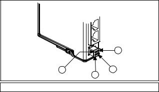
You must connect an external power supply to the NI 9871. This power supply provides the power for the RS485/RS422 transceivers on the module. You can use the included female four-position pigtail to connect to an external voltage source.
Figure 1 lists the connections between an external voltage source (of +8 V to +28 V) and the NI 9871.
|
|
|
2 |
|
1 |
3 |
4 |
|
|
|
|
1 VSUP |
2 VSUP |
3 COM |
4 COM |
Figure 1. Four-Position External Power Connector
NI 9871 Operating Instructions |
8 |
ni.com |
 Loading...