


OPERATING INSTRUCTIONS
NI 9219
4-Channel, 24-Bit, Universal Analog Input Module
These operating instructions describe how to use the National Instruments 9219. For information about installing, configuring, and programming the system, refer to the system documentation. Visit ni.com/info and enter the info code rdsoftwareversion to determine which software you need for the modules you are using.
Note The safety guidelines and specifications in this document are specific to the NI 9219. The other components in the system might not meet the same safety ratings and specifications. Refer to the documentation for each component in the system to determine the safety ratings and specifications for the entire system.
Safety Guidelines
Operate the NI 9219 only as described in these operating instructions.
Hot Surface This icon denotes that the component may be hot. Touching this component may result in bodily injury.
NI 9219 Operating Instructions |
2 |
ni.com |
Safety Guidelines for Hazardous Voltages
If hazardous voltages are connected to the module, take the following precautions. A hazardous voltage is a voltage greater than 42.4 Vpk or 60 VDC to earth ground.
Caution Ensure that hazardous voltage wiring is performed only by qualified personnel adhering to local electrical standards.
Caution Do not mix hazardous voltage circuits and human-accessible circuits on the same module.
Caution Make sure that devices and circuits connected to the module are properly insulated from human contact.
Caution When module terminals are hazardous voltage LIVE (>42.4 Vpk/60 VDC), you must ensure that devices and circuits connected to the module are properly insulated from human contact. You must use the NI 9972 connector backshell kit to ensure that the terminals are not accessible.
© National Instruments Corp. |
3 |
NI 9219 Operating Instructions |
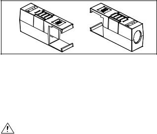
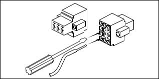
Figure 1 shows the NI 9972 connector backshell.
Figure 1. NI 9972 Connector Backshell
Safety Guidelines for Hazardous Locations
The NI 9219 is suitable for use in Class I, Division 2, Groups A, B, C, D, T4 hazardous locations; Class I, Zone 2, AEx nC IIC T4 hazardous locations; and nonhazardous locations only. Follow these guidelines if you are installing the NI 9219 in a potentially explosive environment. Not following these guidelines may result in serious injury or death.
Caution Do not disconnect I/O-side wires or connectors unless power has been switched off or the area is known to be nonhazardous.
NI 9219 Operating Instructions |
4 |
ni.com |
Caution Do not remove modules unless power has been switched off or the area is known to be nonhazardous.
Caution Substitution of components may impair suitability for Class I, Division 2.
Caution For Zone 2 applications, install the system in an enclosure rated to at least IP 54 as defined by IEC 60529 and EN 60529.
Special Conditions for Marine Applications
Some modules are Lloyd’s Register (LR) Type Approved for marine applications. To verify Lloyd’s Register certification, visit ni.com/certification and search for the LR certificate, or look for the Lloyd’s Register mark on the module.
Caution To meet radio frequency emission requirements for marine applications, use shielded cables and install the system in a metal enclosure. Suppression ferrites must be installed on power supply inputs near power entries to modules and controllers. Power supply and module cables must be separated on opposite sides of the enclosure and must enter/exit through opposing enclosure walls.
© National Instruments Corp. |
5 |
NI 9219 Operating Instructions |

Wiring the NI 9219
The NI 9219 has four 6-terminal connectors that provide connections for four analog input channels. Connect the positive signal of the signal source to the positive input signal terminal (HI) and the negative signal of the signal source to the negative input signal terminal (LO). Use the excitation terminals if your sensor requires a separate excitation connection. Refer to Table 1 for the signal names and Table 2 for the terminal assignments for each mode. Refer to the NI 9219 Circuitry section for information about connections in each mode.
NI 9219 Operating Instructions |
6 |
ni.com |

|
|
|
Table 1. |
Signal Names |
|
|
|
|
|
Signal |
|
|
Module |
|
Terminal |
Name |
Signal Description |
|
|
|
1 |
T+ |
TEDS Data |
|
1 |
4 |
2 |
T– |
TEDS COM |
Ch 0 |
2 |
5 |
|||
3 |
6 |
|
|
|
|
|
|
|
|
||
Ch 1 |
1 |
4 |
3 |
EX+/HI* |
Positive excitation or |
2 |
5 |
|
|
input signal |
|
|
3 |
6 |
|
|
|
|
1 |
4 |
4 |
HI |
Positive input signal |
Ch 2 |
2 |
5 |
|
|
|
|
3 |
6 |
|
|
|
|
1 |
4 |
5 |
EX–/LO* |
Negative excitation or |
|
|
|
input signal |
||
Ch 3 |
2 |
5 |
|
|
|
|
3 |
6 |
|
|
|
|
|
|
6 |
LO |
Negative input signal |
* Depending on the mode, terminals 3 and 5 are either the excitation signals or the input signals.
© National Instruments Corp. |
7 |
NI 9219 Operating Instructions |
|
Table 2. |
Terminal Assignments |
|
|
|||
|
|
|
|
|
|
|
|
|
|
|
|
Terminal |
|
|
|
|
|
|
|
|
|
|
|
Mode |
1 |
|
2 |
3 |
4 |
5 |
6 |
|
|
|
|
|
|
|
|
|
|
|
|
|
|
|
|
Voltage |
T+ |
|
T– |
— |
HI |
LO |
— |
|
|
|
|
|
|
|
|
Current |
T+ |
|
T– |
HI |
— |
LO |
— |
|
|
|
|
|
|
|
|
4-Wire Resistance |
T+ |
|
T– |
EX+ |
HI |
EX– |
LO |
|
|
|
|
|
|
|
|
2-Wire Resistance |
T+ |
|
T– |
HI |
— |
LO |
— |
|
|
|
|
|
|
|
|
Thermocouple |
T+ |
|
T– |
— |
HI |
LO |
— |
|
|
|
|
|
|
|
|
4-Wire RTD |
T+ |
|
T– |
EX+ |
HI |
EX– |
LO |
|
|
|
|
|
|
|
|
3-Wire RTD |
T+ |
|
T– |
EX+ |
— |
EX– |
LO |
|
|
|
|
|
|
|
|
Quarter-Bridge |
T+ |
|
T– |
HI |
— |
LO |
— |
|
|
|
|
|
|
|
|
Half-Bridge |
T+ |
|
T– |
EX+ |
HI |
EX– |
— |
|
|
|
|
|
|
|
|
Full-Bridge |
T+ |
|
T– |
EX+ |
HI |
EX– |
LO |
|
|
|
|
|
|
|
|
Digital In |
T+ |
|
T– |
— |
HI |
LO |
— |
|
|
|
|
|
|
|
|
Open Contact |
T+ |
|
T– |
HI |
— |
LO |
— |
|
|
|
|
|
|
|
|
NI 9219 Operating Instructions |
8 |
ni.com |
Connecting Wires to the NI 9219 Connectors
Use a flathead screwdriver with a blade smaller than 2.3 × 1.0 mm (0.09 × 0.04 in.) to connect wires to the detachable spring-terminal connectors. Insert the screwdriver into a spring clamp activation slot and press a wire into the corresponding connector terminal, then remove the screwdriver to clamp the wire into the terminal. Refer to the Specifications section for more information about spring-terminal wiring. Refer to Figure 2 for an illustration of connecting wires to the NI 9219.
Figure 2. Connecting Wires to the NI 9219 Connectors
© National Instruments Corp. |
9 |
NI 9219 Operating Instructions |

Wiring TEDS Channels
The NI 9219 supports only Class II TEDS sensors. Connect the two TEDS lines to TEDS Data (T+) and TEDS COM (T–) and ensure that neither T+ nor T– is tied in common to any of the signal inputs (terminals 3 through 6) on the NI 9219. Visit ni.com/info and enter the info code rdteds for information about TEDS sensors.
Grounding and Shielding Considerations
You can connect ground-referenced or floating signal sources to the NI 9219. If you make a floating connection between the signal source and the NI 9219, make sure the voltages on the positive and negative connections are within the channel-to-earth working voltage range to ensure proper operation of the NI 9219. Refer to the Specifications section for more information about operating voltages and overvoltage protection.
Note For best signal quality, National Instruments recommends using shielded cables and twisted pair wiring whenever possible.
Figures 3 and 4 illustrate connecting grounded and floating signal sources to the NI 9219 in Voltage mode.
NI 9219 Operating Instructions |
10 |
ni.com |
|
|
Shielding |
Twisted-Pair |
|
Signal Source |
Wiring |
|||
|
||||
|
|
|
HI |
|
VSIG |
+ |
|
NI 9219 |
|
– |
|
|||
|
|
|
LO |
|
VSIG Ground |
|
|
||
Reference |
|
|
||
Figure 3. Connecting a Grounded Signal Source to the NI 9219
|
|
Shielding |
Twisted-Pair |
|
Signal Source |
Wiring |
|||
|
||||
|
|
|
HI |
|
VSIG |
+ |
|
NI 9219 |
|
– |
|
|||
|
|
LO |
||
|
|
|
||
Figure 4. Connecting a Floating Signal Source to the NI 9219
© National Instruments Corp. |
11 |
NI 9219 Operating Instructions |
 Loading...