


1
INSTALLER: THESE INSTRUCTIONS MUST BE CONVEYED TO AND REMAIN WITH THE HOMEOWNER.
CERTIFIED UNDER CANADIAN AND AMERICAN NATIONAL STANDARDS, CSA 2.33, ANSI Z21.88 FOR VENTED GAS FIREPLACE HEATERS
GAS INSERT
INSTALLATION AND OPERATION INSTRUCTIONS FOR
GAS-FIRED VENTED ROOM HEATER
NATURAL GAS MODEL PROPANE GAS MODEL
GI3016-N GI3016-P
GAS-ZERO CLEARANCE WHEN INSTALLED WITH GI-700 KIT (FLUSH FRONT & LOUVRES) WITHOUT GI-700 KIT INSTALL RECESSED INTOAWOODBURNING NON-COMBUSTIBLE FIREPLACE
CERTIFICATION LABEL AFFIXED TO UNDERSIDE OF FRESH AIR DAMPER
WARNING: If the information in these instructions is not followed exactly, a fire or explosion may result causing property damage, personal injury or death.
FOR YOUR SAFETY
Do not store or use gasoline or other flammable vapours and liquids in the vicinity of this or any other appliance.
WHAT TO DO IF YOU SMELL GAS:
•Do not try to light any appliance.
•Do not touch any electrical switch.
• Immediately call your gas supplier from a neighbor's phone. Follow the gas sup-
•Do not use any phone in your building. plier's instructions.
•If you cannot reach your gas supplier,
call the fire department. Installation and service must be performed by a qualified installer, service
agency or the gas supplier.
Wolf Steel Ltd., 24 Napoleon Rd., Barrie, ON L4M 4Y8 Canada • (705)721-1212 • fax(705)722-6031 www.napoleonfireplaces.com • ask@napoleon.on.ca
W415-0171/D/01.06.04

2
TABLE of CONTENTS
PG 2-5 |
INTRODUCTION |
10-11 |
OPERATION / MAINTENANCE |
|
|
Warranty |
|
Operating Instructions |
|
|
General Instructions |
|
Fresh Air Damper System |
|
|
Mantle Clearance |
|
Maintenance |
|
|
General Information |
11 |
BLOWER INSTALLATION |
|
|
Care of Glass, Enamelled & Plated Parts |
|||
5-6 |
INSTALLATION |
|
Blower Replacement Instructions |
|
11 |
ADJUSTMENTS |
|||
|
Gas Installation |
|||
|
|
Venturi Adjustments |
||
|
Spill Switch |
|
||
|
|
Pilot Burner Adjustment |
||
|
Venting Action Check |
|
||
|
|
|
||
6-9 |
FINISHING |
12-13 |
REPLACEMENTS |
|
|
Ordering Replacement Parts |
|||
|
Brick Panel Installation |
|
||
|
|
Replacement Parts |
||
|
Log Placement/Charcoal Embers |
|
||
|
|
Accessories |
||
|
Glass, Flashing Kit, Logo Placement, |
|
||
|
|
|
||
|
Louvre, Inset & Bay Kit Installation |
14-15 |
TROUBLE SHOOTING GUIDE |
PLEASE RETAIN THIS MANUAL FOR FUTURE REFERENCE
WARNING
•Adults and especially children should be alerted to the hazards of high surface temperatures and should stay away to avoid burns or clothing ignition. Supervise young children when they are in the same room as the fireplace.
•Clothing or other flammable material should not be placed on or near the fireplace.
•Any safety screen or guard removed for servicing must be replaced prior to operating the fireplace.
•This fireplace must not be connected to a chimney flue pipe serving a separate solid fuel burning appliance.
•Do not operate the fireplace with the glass door removed, cracked or broken. Replacement of the glass should be done by a licensed or qualified service person.
•Do not strike or slam shut the fireplace glass door.
•Due to high temperatures, the fireplace should be located out of traffic and away from furniture and draperies.
•It is imperative that the control compartments, burners and circulating blower and its passageway in the fireplace and venting system are kept clean. The fireplace and its venting system should be inspected before use and at least annually by a qualified service person. More frequent cleaning may be required due to excessive lint from carpeting, bedding material, etc. The fireplace area must be kept clear and free from combustible materials, gasoline and other flammable vapours and liquids.
•Do not use this fireplace if any part has been under water. Immediately call a qualified service technician to inspect the fireplace and to replace any part of the control system and any gas control which has been under water.
•Under no circumstances should this fireplace be modified.
•Do not burn wood or other materials in this fireplace.
NOTE: CHANGES, OTHER THAN EDITORIAL, ARE DENOTED BY A VERTICAL LINE IN THE MARGIN
W415-0171/D/01.06.04

3
NAPOLEON gas fireplaces are manufactured under the strict Standard of the world recognized ISO 9001 : 2000 Quality Assurance Certificate.
NAPOLEON products are designed with superior components and materials, assembled by trained craftsmen who take great pride in their work. The burner and valve assembly are leak and test-fired at a quality test station. The complete fireplace is thoroughly inspected by a qualified technician before packaging to ensure that you, the customer, receives the quality product that you expect from NAPOLEON.
NAPOLEON GAS FIREPLACE PRESIDENT'S LIFETIME LIMITED WARRANTY
The following materials and workmanship in your new NAPOLEON gas fireplace are warranted against defects for as long as you own the fireplace. This covers: combustion chamber, heat exchanger, stainless steel burner, phazer™ logs and embers, ceramic glass (thermal breakage only), gold plated parts against tarnishing, porcelainized enamelled components and aluminum extrusion trims.
Electrical (110V and millivolt) components and wearable parts such as blowers, gas valves, thermal switch, switches, wiring, remote controls, ignitor, gasketing, and pilot assembly are covered and NAPOLEON will provide replacement parts free of charge during the first year of the limited warranty.
Labour related to warranty repair is covered free of charge during the first year. Repair work, however, requires the prior approval of an authorized company official. Labour costs to the account of NAPOLEON are based on a predetermined rate schedule and any repair work must be done through an authorized NAPOLEON dealer.
CONDITIONS AND LIMITATIONS
NAPOLEON warrants its products against manufacturing defects to the original purchaser only -- i.e., the individual or legal entity (registered customer) whose name appears on the warranty registration card filed with NAPOLEON -- provided that the purchase was made through an authorized NAPOLEON dealer and is subject to the following conditions and limitations:
This factory warranty is nontransferable and may not be extended whatsoever by any of our representatives.
The gas fireplace must be installed by a licenced, authorized service technician or contractor. Installation must be done in accordance with the installation instructions included with the product and all local and national building and fire codes.
This limited warranty does not cover damages caused by misuse, lack of maintenance, accident, alterations, abuse or neglect and parts installed from other manufacturers will nullify this warranty.
This limited warranty further does not cover any scratches, dents, corrosion or discolouring caused by excessive heat, abrasive and chemical cleaners nor chipping on porcelain enamel parts, mechanical breakage of PHAZER™ logs and embers, nor any venting components used in the installation of the fireplace.
NAPOLEON warrants its stainless steel burners against defects in workmanship and material for life, subject to the following conditions: During the first 10 years NAPOLEON will replace or repair the defective parts at our option free of charge. From 10 years to life, NAPOLEON will provide replacement burners at 50% of the current retail price.
In the first year only, this warranty extends to the repair or replacement of warranted parts which are defective in material or workmanship provided that the product has been operated in accordance with the operation instructions and under normal conditions.
After the first year, with respect to this President's Limited Lifetime Warranty, NAPOLEON may, at its discretion, fully discharge all obligations with respect to this warranty by refunding to the original warranted purchaser the wholesale price of any warranted but defective part(s).
After the first year, NAPOLEON will not be responsible for installation, labour or any other costs or expenses related to the reinstallation of a warranted part, and such expenses are not covered by this warranty.
Notwithstanding any provisions contained in this President's Limited Lifetime Warranty, NAPOLEON’S responsibility under this warranty is defined as above and it shall not in any event extend to any incidental, consequential or indirect damages.
This warranty defines the obligations and liability of NAPOLEON with respect to the NAPOLEON gas fireplace and any other warranties expressed or implied with respect to this product, its components or accessories are excluded.
NAPOLEON neither assumes, nor authorizes any third party to assume, on its behalf, any other liabilities with respect to the sale of this product. NAPOLEON will not be responsible for: over-firing, downdrafts, spillage caused by environmental conditions such as rooftops, buildings, nearby trees, hills, mountains, inadequate vents or ventilation, excessive venting configurations, insufficient makeup air, or negative air pressures which may or may not be caused by mechanical systems such as exhaust fans, furnaces, clothes dryers, etc.
Any damages to fireplace, combustion chamber, heat exchanger, brass trim or other component due to water, weather damage, long periods of dampness, condensation, damaging chemicals or cleaners will not be the responsibility of NAPOLEON.
The bill of sale or copy will be required together with a serial number and a model number when making any warranty claims from your authorized dealer. The warranty registration card must be returned within fourteen days to register the warranty.
NAPOLEON reserves the right to have its representative inspect any product or part thereof prior to honouring any warranty claim.
ALL SPECIFICATIONS AND DESIGNS ARE SUBJECT TO CHANGE WITHOUT PRIOR NOTICE DUE TO ON-GOING PRODUCT IMPROVEMENTS. NAPOLEON® IS A REGISTERED TRADEMARK OF WOLF STEEL LTD. PATENTS U.S. 5.303.693.801 - CAN. 2.073.411, 2.082.915 & DES 417,497(12.07.1999). © WOLF STEEL LTD.
W415-0171/D/01.06.04

4
GENERAL INSTRUCTIONS
Installation practices vary from region to region and it is important to know the specifics that apply to your area, for example: in Massachusetts State:
•The fireplace damper must be removed or welded in the open position prior to installation of a fireplace insert or gas log.
•The appliance off valve must be a “T” handle gas cock.
•The flexible connector must not be longer than 36 inches.
•The appliance is not approved for installation in a bedroom or bathroom unless the unit is a direct vent sealed combustion product.
•WARNING: This product must be installed by a licensed plumber or gas fitter when installed within the commonwealth of
Massachusetts.
In absence of local codes, install to the current CAN1-B149
Installation Code in Canada or to the National Fuel Gas Code, ANSI Z223.1, and NFPA 54 in the United States.
Purge all gas lines with the glass door of the fireplace removed. Assure that a continuous gas flow is at the burner before installing the door.
Under extreme vent configurations, allow several minutes (5-15) for the flame to stabilize after ignition. Altitudes
greater than 4,000 ft. require a minimum vent run of 12 ft.
The heater and its individual shutoff valve must be disconnected from the gas supply piping system during any pressure testing of that system at test pressures in excess of ½ psig (3.5 kPa). The fireplace must be isolated from the gas supply piping system by closing its individual manual shutoff valve during any pressure testing of the gas supply piping system at test pressures equal to or less than ½ psig (3.5 kPa).
A 1/8 inch NPT plug, accessible for test gauge connection, must be installed immediately upstream of the gas supply connection to the fireplace.
This fireplace must be connected to any accepted lined chimney system listed to ULC-S635M (in Canada) or UL-1777 (in USA). The venting connection must be in compliance with the chimney manufacturers installation instructions.
The draft hood must be installed so that it is in the same atmospheric pressure zone as the combustion air inlet to the fireplace.
This heater can be installed two different ways. If installed as is, it must be recessed into a vented noncombustible woodburning fireplace (prefabricated or masonry) only. This is referred to as an INSERT type of installation.
The minimum fireplace size in which the heater is to be installed is: HEIGHT 21 inches
WIDTH 26½ inches DEPTH 17½ inches
If installed in conjunction with kit #GI-700, it may be framed into an enclosure made of combustible materials. This is referred to as a ZERO CLEARANCE type of installation. This heater may only be installed in the GI-700 when using the glass front kit, GI-FF, as well as one louvre kit, GI-LPB, GI-LAB, GI-LG or GI-LK. The minimum clearance to combustible construction in this form of installation is:
MANTLE HEIGHT* |
7 inches** |
SIDES, BACK, BOTTOM & TOP |
0 inches |
B-VENT |
1 inch |
RECESSED DEPTH |
18½ inches |
* MEASUREMENTS TAKEN FROM KIT STANDOFFS. SEE KIT INSTRUCTIONS
**MAXIMUM HORIZONTAL EXTENSION IS 6 INCHES.
Objects placed in front of the fireplace must be kept a minimum of 48" away from the front face.
W415-0171/D/01.06.04
The fireplace, when installed, must be electrically connected and grounded in accordance with local codes. In the absence of local codes, use the current CSA C22.1 CANADIAN ELECTRICAL CODE in Canada or the ANSI/NFPA 70 NATIONAL ELECTRICAL CODE in the United States. The blower power cord must be connected into a properly grounded receptacle. The grounding prong must
not be removed from the cord plug.
Provide adequate ventilation and combustion air. Provide adequate accessibility clearance for servicing and operating the fireplace. Never obstruct the front opening of the fireplace.
MANTLE CLEARANCE
Mantle clearance, while |
FIGURE1 |
||
conforming |
to |
the |
|
stated clearance |
to |
|
|
combustible materials, |
|
||
can vary according to |
|
||
the mantle |
depth. |
|
|
These clearances do not apply to a GI-700 kit type installation.
GENERAL INFORMATION
FOR YOUR SATISFACTION, THIS FIREPLACE HAS BEEN TEST-FIRED TO ASSURE ITS OPERATION AND QUALITY! Maximum input is 30,000 BTU/hr for natural gas and 24,000 BTU/hr for propane. When the fireplace is installed at elevations above 4,500 ft., and in the absence of specific recommendations from the local authority having jurisdiction, the certified high altitude input rating shall be reduced at the rate of 4% for each additional 1,000 ft. Maximum output for natural gas is 22,800 BTU/hr at an efficiency of 76% with the fan on, 72% with the fan off; and 18,240 BTU/hr for propane at an efficiency of 76% with the fan on, 71% with the fan off. Minimum A.F.U.E.(Annual Fuel Utilization Efficiency) rating is 64% for both natural and propane gas. Where the fireplace has been factory equipped for hi-altitude, the input has been downrated by 10%. This fireplace is approved for bathroom, bedroom and bed-sitting room installations and is suitable for mobile home installation.
Minimum inlet gas supply pressure is 4.5 inches water column for natural gas and 11 inches water column for propane. Maximum inlet gas pressure is 7 inches water column for natural gas and 13 inches water column for propane. Manifold pressure under flow conditions is 3.5 inches water column for natural gas and 10 inches water column for propane.
No external electricity (110 volts or 24 volts) is required
for the gas system operation.
Change in flame appearance from "HI" to "LO" is more evident in natural gas than in propane. The self generating pilot provides current for a remote burner On-Off switch.
5
CARE OF GLASS, ENAMELLED AND PLATED PARTS
Do not use abrasive cleaners to clean these parts. Buff lightly with a clean dry cloth. Porcelain enamelled components must be handled with care. The baked-on finish is glasslike. If struck, it will chip! Touch-up paint is available through your Napoleon dealer.
The glass is 3/16" ceramic glass available from your Napoleon dealer. DO NOT SUBSTITUTE MATERIALS. Clean the glass after the first 10 hours of operation with a recommended gas fireplace glass cleaner. Thereafter clean as required. DO NOT CLEAN GLASS WHEN HOT! If the glass is not kept clean permanent discolouration and / or blemishes may result.
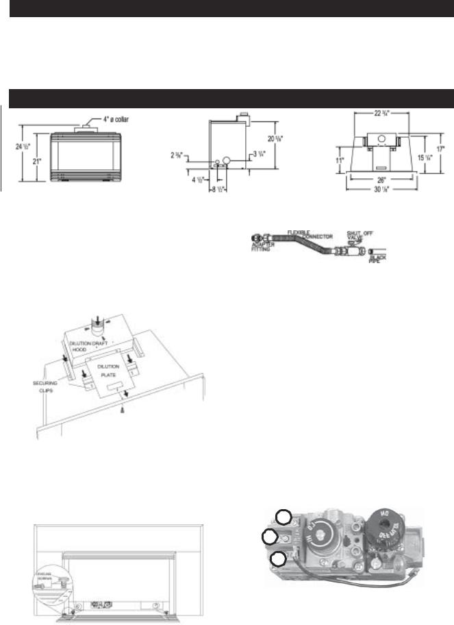
INSTALLATION
FIGURE2
Clean out the ashes from the inside of the woodburning fireplace. Make sure that the chimney and woodburning fireplace are in clean and sound condition. Do not remove bricks or mortar from the masonry fireplace. If necessary have any repair work done by a qualified person before installing the insert. Remove the existing fireplace damper or lock into an open position. Line the chimney with a 4 inch diameter approved liner. Pack insulation around the liner in the damper area to prevent air flow from entering the chimney. Chimney installation must conform to both national and local code requirements. The liner must be continuous from the fireplace to the chimney cap.
FIGURE3
Remove the securing screw from the front of the dilution plate. Push the dilution hood out of its securing clip and attach the liner using 3 screws equally spaced. Move the insert into the centre of the woodburning fireplace making sure that the dilution draft hood inserts back into its securing clip. Level using the four levelling screws located front and back on either side of the fireplace base.
FIGURE4
Levelling the insert will eliminate rocking or excessive noise when the fan is in operation. Replace the securing screw to the front of the dilution plate.
FIGURE5
Install rigid black pipe, a flex connector, if local codes permit, or 1/2" type L, copper tubing with a 3/8" to 1/2" adapter and a shut off valve to the fireplace. Seal and tighten securely. The adapter will be required between the gas valve and the copper tubing or flex connector.
Do not damage or kink flex connector!
Check for gas leaks by brushing on a soap and water solution.
Do not use open flame!
An on/off switch has been included and can be located at the lower right, behind the louvre access door or at the right side trim.
For ease of accessibility, this switch may be replaced with a wall switch or substituted with a millivolt thermostat that may be installed in a convenient location on any wall. Route 2-strand (solid core) millivolt wire through the electrical hole located at the bottom right side of the unit. The recommended maximum lead length depends on wire size:
WIRE SIZE |
MAX. LENGTH |
14gauge |
100 feet |
16gauge |
60 feet |
18gauge |
40 feet |
1
2
3
FIGURE6
Attach the two leads to terminals 1 and 3 located on the gas valve.
Do not connect either the wall switch or the gas valve to
electricity (110 volts or 24 volts). |
W415-0171/D/01.06.04 |
 Loading...