


INSTALLER: LEAVE THIS MANUAL WITH THE APPLIANCE.
CONSUMER: RETAIN THIS MANUAL FOR FUTURE REFERENCE.
NEVER LEAVE CHILDREN OR OTHER AT RISK INDIVIDUALS ALONE WITH THE APPLIANCE
EN
INSTALLATION AND
OPERATING INSTRUCTIONS
FR PG 35
CERTIFIED UNDER CANADIAN AND AMERICAN NATIONAL STANDARDS: CSA C22.2 No. 46 / UL 2021
ADD SAFETY STANDARD INFORMATION...
NEFB33H / NEFB40H
ELECTRIC FIREPLACE
ADD
PR ODUCT
IMAGE
SAFETY INFORMATION
! WARNING
If the information in these instructions are not followed exactly, a fire may result causing property damage, personal injury or loss of life.
- Do not store or use gasoline or other flammable vapors and liquids in the vicinity of this or any other appliance.
FOR INDOOR USE ONLY!
ADD ETL,
OMNI or CSA
LOGO HERE
Wolf Steel Ltd., 24 Napoleon Rd., Barrie, ON, L4M 0G8 Canada /
103 Miller Drive, Crittenden, Kentucky, USA, 41030
Phone (705)721-1212 • Fax (705)720-9081 • www.napoleonfireplaces.com • hearth@napoleonproducts.com
$10.00 |
1.11 |
|
W415-2165 / E / 02.23.17

2
EN
TABLE OF CONTENTS
1.0 |
INTRODUCTION |
3 |
|
|
1.1 |
DIMENSIONS |
4 |
|
1.2 |
LISTING APPROVALS |
4 |
|
1.3 |
GENERAL INSTRUCTIONS |
5 |
|
1.4 |
UNPACKING AND TESTING APPLIANCE |
5 |
|
1.5 |
RATING PLATE INFORMATION |
6 |
|
1.6 |
LABEL LOCATION |
6 |
2.0 |
LOCATING APPLIANCE |
7 |
|
|
2.1 |
GROUNDING APPLIANCE |
7 |
3.0 |
INSTALLATION |
8 |
|
|
3.1 |
MINIMUM CLEARANCE TO COMBUSTIBLES |
8 |
|
3.2 |
MINIMUM MANTEL CLEARANCES |
8 |
|
3.3 |
FRAMING |
9 |
|
3.3.1 |
APPLIANCE INSTALLATION |
10 |
|
3.3.2 |
VOLTAGE SELECTION |
10 |
|
3.3.3 |
VOLTAGE SELECTOR SWITCH LOCATION |
11 |
|
3.3.4 |
120 VOLT CORD PLUG INSTALLATION |
11 |
|
3.3.5 |
120V HARD WIRING INSTALLATION |
12 |
|
3.3.6 |
240V HARD WIRING INSTALLATION |
14 |
4.0 |
OPERATING INSTRUCTIONS |
16 |
|
|
4.1 |
OPERATING CONTROL PANEL |
16 |
|
4.2 |
OPERATING BY REMOTE CONTROL |
17 |
5.0 |
FINISHING |
18 |
|
|
5.1 |
BRICK PANEL INSTALLATION AND REMOVAL |
18 |
|
5.2 |
GLASS DOOR INSTALLATION |
19 |
6.0 |
MAINTENANCE |
20 |
|
|
6.1 |
LOG, GRATE AND EMBER BED ASSEMBLY REMOVAL |
20 |
|
6.2 |
FLAME PANEL REMOVAL |
21 |
|
6.3 |
FLAME BOARD REMOVAL |
21 |
|
6.4 |
MOTOR REPLACEMENT |
22 |
|
6.5 |
CONTROL BOARD REPLACEMENT |
22 |
|
6.6 |
REMOTE BATTERY INSTALLATION |
22 |
7.0 |
WIRING DIAGRAM |
23 |
|
8.0 |
REPLACEMENT PARTS |
24 |
|
|
8.1 |
NEFB33H OVERVIEW |
25 |
|
8.2 |
NEFB33H LOG ASSEMBLY (W010-3317) |
26 |
|
8.3 |
NEFB40H OVERVIEW |
27 |
|
8.4 |
NEFB40H LOG ASSEMBLY (W010-3318) |
28 |
9.0 |
TROUBLESHOOTING |
29 |
|
10.0 |
WARRANTY |
30 |
|
11.0 |
SERVICE HISTORY |
31 |
|
12.0 |
NOTES |
|
32 |
NOTE: Changes, other than editorial, are denoted by a vertical line in the margin.
Batteries must be disposed of according to the local laws and regulations. Some batteries may be recycled, and may be accepted for disposal at your local recycling center. Check with your municipality for recycling instructions.
W415-2165 / E / 02.23.17

3
1.0 INTRODUCTION
! WARNING
EN
•IF EQUIPPED WITH A HEATER, THIS APPLIANCE CAN BE HOT WHEN OPERATED AND CAN CAUSE SEVERE BURNS IF CONTACTED.
•Do not operate appliance before reading and understanding operating instructions. Failure to operate appliance according to operating instructions could cause fire or injury.
•Do not install damaged, incomplete or substitute components.
•Do not burn wood or other materials in this appliance.
•All electric appliances have hot and arcing or sparking parts inside. Do not use it in areas where a gas line, paint or flammable liquids are present.
•Any safety screen or guard removed for servicing must be replaced prior to operating the appliance.
•It is imperative that the control compartments, circulating blower and its passageway in the appliance are kept clean. The appliance should be inspected before use and at least annually by a qualified service person. More frequent cleaning may be required due to excessive lint from carpeting, bedding material, etc. The appliance area must be kept clear and free from combustible materials, gasoline and other flammable vapors and liquids.
•Under no circumstances should this appliance be modified.
•Do not use this appliance if any part has been under water. Immediately call a qualified service technician to inspect the appliance and to replace any part of the control system which has been under water.
•Do not operate the appliance with the glass door removed, cracked or broken. Replacement of the glass should be done by a licensed or qualified service person.
•Do not strike or slam shut the appliance glass door.
•Keep the packaging material out of reach of children and dispose of the material in a safe manner. As with all plastic bags, these are not toys and should be kept away from children and infants.
•Servicing should be done only while the appliance is disconnected from the power supply circuit.
•Always unplug appliance when not in use.
•Do not operate this appliance with a damaged cord or plug after the appliance malfunctions, has been dropped or damaged in any manner. Return appliance to authorized service facility for examination, electrical or mechanical adjustment, or repair.
•Do not use outdoors.
•Never locate appliance where it may fall into a bathtub or other water container.
•Do not run cord under carpeting. Do not cover cord with throw rugs, runners, or the like. Arrange cord away from traffic area and where it will not be tripped over.
•Connect to properly grounded outlets only.
•Do not insert or allow foreign objects to enter any ventilation or exhaust opening as this may cause an electric shock or fire, or damage the appliance.
•To prevent a possible fire, do not block air intakes or exhaust in any manner. Do not use on soft surfaces, like a carpet, where openings may become blocked.
•Always plug appliances directly into a wall outlet/receptacle. Never use an extension cord or relocatable power tap (outlet/power strip).
•These appliances are tested and listed for use only with the optional accessories listed in these instructions. Use of optional accessories not specifically tested for this appliance could void the warranty and/or result in a safety hazard.
For appliances equipped with a heater:
•Risk of burns. Power to the appliance should be turned off and the appliance allowed to cool before servicing. To disconnect power to the appliance, turn controls to off, then remove plug from outlet.
•Young children should be carefully supervised when they are in the same room as the appliance. Toddlers, young children and others may be susceptible to accidental contact burns. A physical barrier is recommended if there are at risk individuals in the house. To restrict access to an appliance or stove, install an adjustable safety gate to keep toddlers, young children and other at risk individuals out of the room and away from hot surfaces.
•Clothing or other flammable material should not be placed on or near the appliance.
•Due to high temperatures, the appliance should be located out of traffic and away from furniture and draperies.
•Ensure you have incorporated adequate safety measure to protect infants/toddlers from touching hot surfaces.
•Even after the appliance is out, the glass and/or screen will remain hot for an extended period of time.
•Check with your local hearth specialty dealer for safety screens and hearth guards to protect children from hot surfaces. These screens and guards must be fastened to the floor.
•Ensure clearances to combustibles are maintained when building a mantel or shelves above the appliance. Elevated temperatures on the wall or in the air above the appliance can cause melting, discoloration or damage to decorations, a T.V. or other electronic components.
3.2
W415-2165 / E / 02.23.17
4
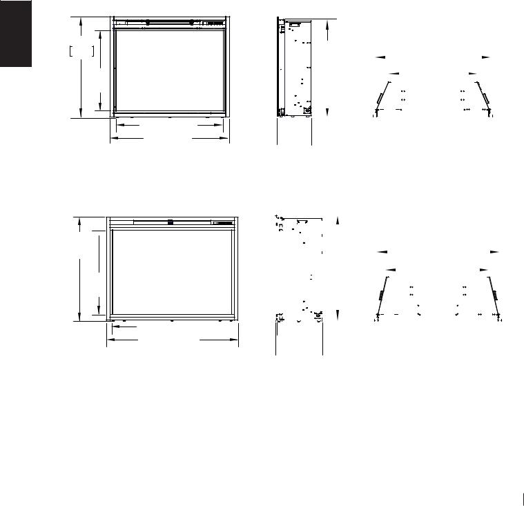
1.1DIMENSIONS
EN
28 3/4" 730mm
23 1/2" [597mm]
31 1/4" [794mm]
34" [864mm]
NEFB33H ILLUSTRATED
32"  [812mm]
26 3/4" [678mm]
37 5/8" [956mm] 

40 3/8" [1025mm]
NEFB40H ILLUSTRATED
1.2LISTING APPROVALS
28 1/8" |
|
|
|
|
|
|
|
|
|
|
|
|
|
|
|
|
|
[715mm] |
|
|
|
|
|
32 1/2" [826mm] |
|
|
|
|
|
||||||
|
|
|
|
|
|
|
|
||||||||||
|
|
|
|
|
|
|
|
|
25 1/4" [641mm] |
|
|
|
|
|
|
|
|
|
|
|
|
|
|
|
|
|
|
|
|
|
|
|
|||
|
|
|
|
|
|
|
|
|
|
|
|||||||
|
|
|
|
|
|
|
|
|
|
|
|
|
|
|
|
|
|
|
|
|
|
|
|
|
|
|
|
|
|
|
|
|
|
|
|
|
|
|
|
|
|
|
|
|
|
|
|
|
|
|
|
|
|
 9 1/2"
  [248mm]
  9 3/4"
[248mm]
|
|
|
|
|
|
|
|
|
|
|
|
|
|
|
|
|
|
38 7/8" [987mm] |
|
|
|
|
|
|
|
|
|
|
|
|
|
|
|
|
|
|
|
|
|
|
|
|
|
|
|
|
|
||
|
|
|
|
|
|
|
|
|
|
|
|
|
|
|
|
|
|
|
|
|
|
|
||
|
|
|
|
|
|
|
|
|
|
|
|
|
|
|
|
|
|
|
|
|
|
|
||
|
|
|
|
|
|
|
31 3/8" |
|
|
|
|
|
|
|
|
|
|
|
|
|
|
|||
|
|
|
|
|
|
|
|
|
|
|
|
|
|
|
|
|
|
|||||||
|
|
|
|
|
|
|
|
|||||||||||||||||
|
|
|
|
|
|
|
|
|
|
|
|
|
|
|
|
|
||||||||
|
|
|
|
|
|
|
[797mm] |
|
|
|
|
|
|
33 3/4" [831mm] |
|
|
|
|
|
|
||||
|
|
|
|
|
|
|
|
|
|
|
|
|
|
|
|
|
|
|
|
|
|
|
||
|
|
|
|
|
|
|
|
|
|
|
|
|
|
|
|
|
|
|
|
|||||
|
|
|
|
|
|
|
|
|
|
|
|
|
|
|
|
|
|
|
|
|
|
|
|
|
|
|
|
|
|
|
|
|
|
|
|
|
|
|
|
|
|
|
|
|
|
|
|
|
|
|
|
|
|
|
|
|
|
|
|
|
|
|
|
|
|
|
|
|
|
|
|
|
|
|
 13 3/4"
  [349mm]
  14"
14"  [356mm]
This appliance has been tested in accordance with the CSA Standards for fixed and location-dedicated electric room appliances in the United States and Canada. If you need assistance during installation, please
contact your local dealer.
NOTE: This appliance must be electrically wired and grounded in accordance with local codes or, in the absence of local codes, with National Electric Code ANSI/ NFPA 70-latest edition in the United States or the Canadian Electric Code, CSA C22.1 in Canada.
Model No. |
NEFB33H |
NEFB40H |
|
|
|
Description |
33" Electric |
40" Electric Fireplace |
|
Fireplace |
|
Voltage |
120/240V |
120/240V |
Watts |
1325/2650W |
1325/2650W |
Amps |
15 AMP Grounded |
15 AMP Grounded |
|
Circuit |
Circuit |
Appliance Width |
34" |
40 3/8" |
|
(864mm) |
(1025mm) |
Appliance Height |
28 3/4" |
32" |
|
(730mm) |
(812mm) |
Appliance Depth |
9 3/4" |
14" |
|
(248mm) |
(356mm) |
Net Weight |
59lbs (27kg) |
82 lbs (37kg) |
Gross Weight |
74 lbs (33kg) |
101 lbs (46kg) |
W415-2165 / E / 02.23.17

5
1.3GENERAL INSTRUCTIONS
•Prior to plugging your appliance into an electrical outlet, verify that the house circuit breakers for the
outlet are on. |
EN |
•The appliance may emit a slight, harmless odour when first used. This odour is normal and it is caused by the initial heating of internal appliance elements and will not occur again.
•If your appliance does not emit heat, consult the “OPERATION” section of this manual for further information.
•Use with a CSA or UL certified surge protector.
•Do not route the power cord directly underneath the appliance.
This electric appliance meets the construction and safety standards of H.U.D. for application in
manufactured homes when installed according to these instructions.
4.6
As with most electronic devices, your new electric fireplace has been designed to operate at temperatures between 5°C (41°F) and 35° C (95°F). During the colder winter months, allow the fireplace to reach room temperature before turning it on.
1.4UNPACKING AND TESTING APPLIANCE
Carefully remove the appliance from the box. Prior to installing the appliance, remove all packaging material and test to make sure the appliance operates properly by plugging the power supply cord into a conveniently located 120V, 15 Amp minimum grounded outlet.
NOTE: The appliance is factory wired for 120 volt power supply. If 240 volt operation is required, see "240V HARD WIRING INSTALLATION" section.
W415-2165 / E / 02.23.17
6
1.5RATING PLATE INFORMATION
EN |
|
|
|
|
|
|
|
|
|
|
|
|
|
|
|
|
|
|
|
|
|
|
|
|
|
|
|
|
|
|
|
|
|
|
|
|
|
|
CERTIFIED UNDER |
CANADIAN AND AMERICAN NATIONAL STANDAR |
|
|
A 22.2 NO. 46 AND UL 2021 / |
||||||||||||||||||||||||||||||||||
D: CS |
||||||||||||||||||||||||||||||||||||||
HOMOLOGUÉ SELON LES |
NORMES NATIONALES CANADIENNES ET |
AMÉRICAIN |
ES:CSA 22.2 NO. 46 UL 2021 |
|||||||||||||||||||||||||||||||||||
ELECTRIC FIREPLACE. |
SUITABLE FOR |
|
|
|
|
|
|
|
|
|
|
|
|
|
|
|
|
|
|
|
FOYER |
|
|
|
|
|
E. HOMOLOGUÉ POUR |
|||||||||||
|
|
|
|
|
|
|
|
|
|
|
|
|
|
|
|
|
|
R À ÉLECTRIQU |
||||||||||||||||||||
BEDROOM AND BED-SITTING ROOM |
|
|
|
|
|
|
|
|
|
|
|
|
|
|
|
|
|
|
|
INSTALL |
ATION DANS |
UNE CHAMBRE À |
||||||||||||||||
INSTALLATION. SUITABLE FOR MOBILE |
|
|
|
|
|
|
|
|
|
|
|
|
|
|
|
|
SALLE DE BAIN ET UN STUDIO. |
|||||||||||||||||||||
|
|
|
|
|
|
|
|
|
|
|
COUCHER, UNE |
|||||||||||||||||||||||||||
HOME INSTALLATION. |
|
|
|
|
|
|
|
|
|
|
|
|
|
|
|
|
|
|
|
|
|
|
|
|
APPROPRIÉ P |
OUR INSTALLATION DANS UNE |
||||||||||||
|
|
|
|
|
|
|
|
|
|
|
|
|
|
|
|
|
|
|
|
|
|
|
|
|
|
|
MAISON MOBILE. |
|
||||||||||
|
|
|
|
|
|
|
|
|
|
|
|
|
|
|
|
|
|
|
|
|
|
|
|
|
|
|||||||||||||
|
|
|
|
|
|
|
|
|
|
|
|
|
|
|
|
|
|
|
|
|
|
|
|
|
|
|||||||||||||
MASTER CONTRACT: 161746 |
|
|
|
|
|
|
|
|
|
|
|
CONTRAT-CADRE: 161746 |
|
|||||||||||||||||||||||||
|
|
|
|
|
NEFB33HH |
|
|
|
|
|
|
|
|
|
|
|
|
|
|
|
|
|
|
|
||||||||||||||
|
|
|
|
|
|
|
MODEL |
|
|
|
|
|
|
|
|
|
|
|
|
|
|
|||||||||||||||||
|
|
|
|
|
|
|
|
|
|
|
|
|
|
|
|
|
|
|
|
|
|
|
||||||||||||||||
|
|
|
VOLTAGE: |
120/ |
|
|
|
|
|
|
|
|
|
|
|
|
SION: 120/240 V |
|
||||||||||||||||||||
|
|
|
240 V |
|
TEN |
|
||||||||||||||||||||||||||||||||
|
|
|
|
FRE |
|
|
|
|
|
|
|
|
|
|
|
|
|
|
FRÉQUENCE: 60Hz |
|
||||||||||||||||||
|
|
|
QUENCY: |
|
||||||||||||||||||||||||||||||||||
|
|
|
|
60Hz |
|
|||||||||||||||||||||||||||||||||
|
|
POWER: 1 |
|
|
|
|
|
|
PUISSANCE: 1325W/2650W |
|
||||||||||||||||||||||||||||
|
|
325W/2650W |
|
|||||||||||||||||||||||||||||||||||
|
|
|
DA |
|
|
|
|
|
|
|
|
|
|
|
CODE DE DATE: |
|
||||||||||||||||||||||
|
|
|
XXXXX |
|
||||||||||||||||||||||||||||||||||
|
|
|
TE CODE: |
|
||||||||||||||||||||||||||||||||||
DESIGNED INN NORTH ERIC |
A |
|
DÉSIGNÉ AMÉRIQUE DU |
|
||||||||||||||||||||||||||||||||||
|
|
|
BY |
|
|
LTD. |
|
NORD PAR WOLF STEEL LTD. |
|
|||||||||||||||||||||||||||||
|
|
|
WOLF STEEL |
|
|
|||||||||||||||||||||||||||||||||
|
|
|
|
|
|
|
||||||||||||||||||||||||||||||||
|
|
|
|
|
|
|
|
E IN CHINA |
FABRIQUÉ EN CHINE |
|
||||||||||||||||||||||||||||
WOLF STEEL LTD. |
|
|
|
|
|
D |
|
|||||||||||||||||||||||||||||||
|
|
|
|
|
|
|
|
|
|
|
|
|
|
|
|
|
|
|
|
|
|
|
|
|
|
|
|
|
|
|
|
|
|
|
|
|
||
24 NAPOLEON ROAD, |
|
|
|
|
|
|
|
|
|
|
|
|
|
|
|
|
|
|
|
|
|
|
|
|
|
|
|
|
|
|
|
|
|
|
|
|
|
|
BARRIE, ON, L4M 0G8 C |
|
|
|
|
SERIAL NUMBER/NO. DE SÉRIE: |
NEFB33H |
W385-2088 / D |
|||||||||||||||||||||||||||||||
ANADA |
|
|
||||||||||||||||||||||||||||||||||||
|
|
|
|
AMPL |
|
|
|
|
|
|
|
|||||||||||||||||||||||||||
|
|
S |
|
|
|
|
|
|
|
|
|
|
|
|
|
|
|
|
|
|
|
|
E |
|
||||||||||||||
For rating plate location, see “LABEL LOCATION” section.
This illustration is for reference only. Refer to the rating plate on the appliance for accurate information.
NOTE: The rating plate must remain with the appliance at all times. It must not be removed.
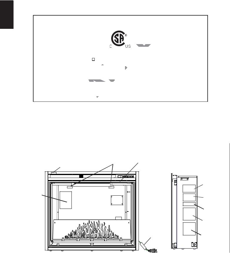
1.6 |
LABEL LOCATION |
|
SERIAL NUMBER |
|
|
|
|
(W385-2091 FOR NEFB33H |
|
|
|
DOOR LATCH LABEL |
W385-2092 FOR NEFB40H) |
|
|
|
NOTE: THE SERIAL NUMBER LABEL |
|
|
|
|
(W385-1954) |
|
|
|
|
IS LOCATED ON THE TOP OF THE |
|
|
|
|
(ON DOOR GLASS) |
|
|
|
"DO NOT COVER" LABEL |
DOOR FRAME |
|
|
|
(W385-1946) |
|
|
|
|
|
|
|
RATING PLATE |
|
|
|
|
NEFB33H |
|
|
|
|
(W385-2088) |
|
|
|
|
NEFB40H |
WIRE DIAGRAM |
|
|
(W385-2089) |
|
|
|
CAUTION LABEL |
||
|
LABEL |
|
|
|
(W385-2090) |
PCB |
|
(W385-1945) |
|
|
|
|
|
|
|
|
|
|
WARNING LABEL |
|
|
|
|
(W385-1944) |
|
|
|
|
120V HARD |
|
|
|
|
WIRING LABEL |
|
|
|
|
(W385-2083) |
|
|
|
WARNING LABEL |
240V HARD |
|
|
|
WIRING LABEL |
|
|
|
|
(W385-1943) |
(W385-2084) |
|
|
|
|
|
|
|
|
|
JUNCTION BOX |
W415-2165 / E / 02.23.17 |
|
|
|
|
7
2.0 LOCATING APPLIANCE
! WARNING
EN
DUE TO HIGH TEMPERATURES, THIS ELECTRIC APPLIANCE SHOULD BE LOCATED OUT OF TRAFFIC. KEEP COMBUSTIBLE MATERIALS SUCH AS FURNITURE, PILLOWS, BEDDING, PAPERS, CLOTHES AND CURTAINS AT LEAST 36" FROM THE FRONT OF THE APPLIANCE.
NEVER LOCATE THIS ELECTRIC APPLIANCE WHERE IT MAY FALL INTO A BATHTUB OR OTHER
WATER CONTAINER.
WEAR SAFETY GLOVES AND SAFETY GLASSES FOR PROTECTION DURING INSTALLATION AND
MAINTENANCE.
TO PREVENT CONTACT WITH SAGGING OR LOOSE INSULATION, THE ELECTRIC APPLIANCE MUST NOT BE INSTALLED AGAINST VAPOR BARRIER OR EXPOSED INSULATION. LOCALIZED OVERHEATING COULD OCCUR AND A FIRE COULD RESULT.
DO NOT EXPOSE THE ELECTRIC APPLIANCE TO THE ELEMENTS (SUCH AS RAIN, ETC.)
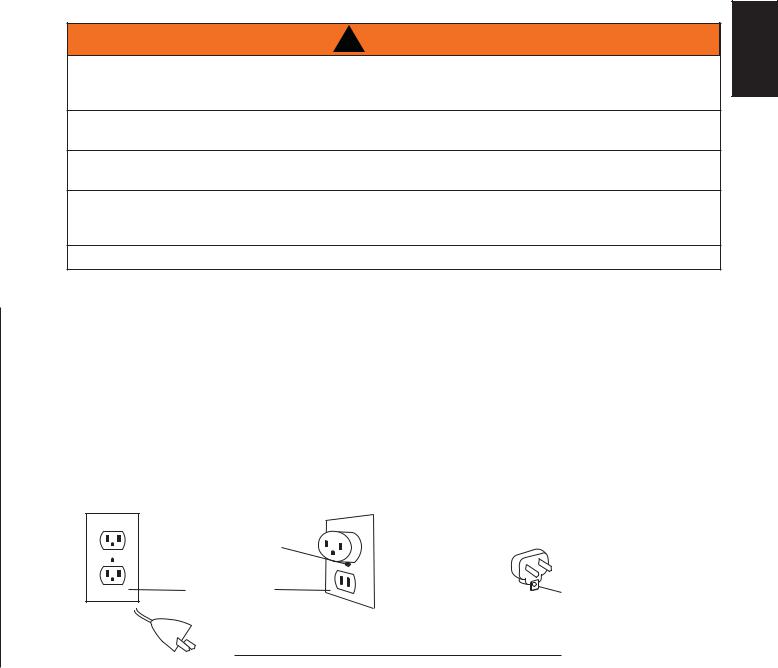
2.1GROUNDING APPLIANCE
NOTE: If this appliance uses 120 volt plug option (factory default setting), the cord has a plug as shown in (A).
An adapter as shown in (C) is available for connecting three-blade grounding type plugs to two-slot receptacles. The green grounding lug extending from the adapter must be connected to a permanent ground such as a properly grounded outlet box. The adapter should not be used if a three-slot grounded receptacle is available.
To disconnect appliance, turn controls to off, then remove plug from outlet.
GROUNDING METHODS
|
METAL SCREW |
|
NOT ALLOWED IN CANADA |
|
|
|
|
ADAPTER |
|
|
COVER OF |
|
|
|
|
|
|
|
|
|
GROUNDED |
|
(C) |
GROUNDING |
(A) |
OUTLET BOX |
(B) |
|
MEANS |
|
|
|||
 GROUNDING PIN
51.1
W415-2165 / E / 02.23.17
8
3.0 INSTALLATION
! WARNING
RISK OF FIRE! THE POWER CORD MUST NOT BE PINCHED AGAINST A SHARP EDGE. SECURE EN CORD TO AVOID TRIPPING OR SNAGGING TO REDUCE THE RISK OF FIRE, ELECTRIC SHOCK OR PERSONAL INJURY. DO NOT RUN CORD UNDER CARPETING. DO NOT COVER CORD WITH THROW RUGS, RUNNERS OR THE LIKE. ARRANGE CORD AWAY FROM TRAFFIC AREAS AND
WHERE IT WILL NOT BE TRIPPED OVER.
RISK OF FIRE! TO PREVENT A POSSIBLE FIRE, DO NOT BLOCK AIR INTAKE OR EXHAUST IN ANY MANNER. DO NOT USE ON SOFT SURFACES WHERE OPENINGS MAY BECOME BLOCKED.
RISK OF FIRE! DO NOT BLOW OR PLACE INSULATION AGAINST THE APPLIANCE.
THIS ELECTRIC APPLIANCE IS TESTED AND LISTED FOR USE ONLY WITH THE APPROVED OPTIONAL ACCESSORIES. USE OF OPTIONAL ACCESSORIES NOT SPECIFICALLY TESTED FOR THIS ELECTRIC APPLIANCE COULD VOID THE WARRANTY AND/OR RESULT IN A SAFETY HAZARD.
IF THE INFORMATION IN THESE INSTRUCTIONS IS NOT FOLLOWED EXACTLY, A FIRE OR EXPLOSION MAY RESULT CAUSING PROPERTY DAMAGE, PERSONAL INJURY OR DEATH. DO NOT STORE OR USE GASOLINE OR OTHER FLAMMABLE VAPORS IN THE VICINITY OF THIS OR ANY OTHER APPLIANCE.
THIS APPLIANCE IS HEAVY. IT IS HIGHLY RECOMMENDED THAT TWO PEOPLE INSTALL
THIS APPLIANCE.
IF YOUR APPLIANCE IS EQUIPPED WITH A HEATER, ENSURE THE HEATER VENTS CANNOT, IN ANY
WAY, BE COVERED AS IT MAY CREATE A FIRE HAZARD.
DO NOT RUN THE POWER CORD HORIZONTALLY, DIRECTLY BELOW THE APPLIANCE.
42.5
Select a suitable location that is not susceptible to moisture and is away from drapes, furniture and high traffic areas.
NOTE: Follow all National and local electrical codes.
3.1MINIMUM CLEARANCE TO COMBUSTIBLES
Measurements are taken from the glass front.
Bottom |
0" |
Top |
1" (25mm) to 2" (51mm) mantel |
Sides |
0" |
Top |
5" (127mm) to ceiling |
Back |
0" |
|
|
NOTE: The power switch is located on the upper right hand side of the appliance. Always ensure that access to this switch remains accessible.
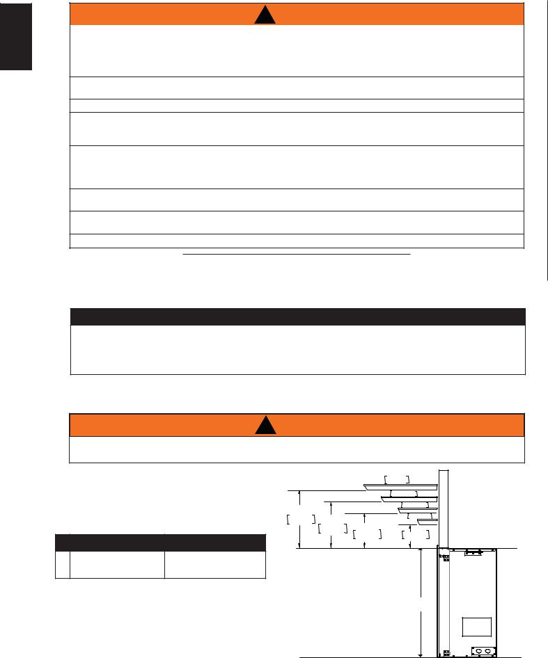
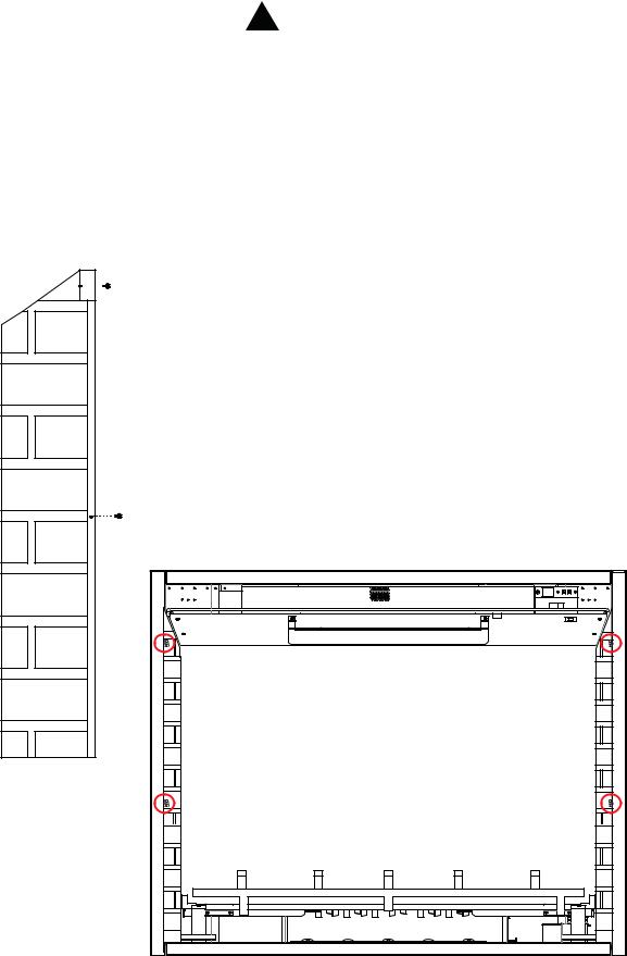
3.2MINIMUM MANTEL CLEARANCES
! WARNING
WHEN USING PAINT OR LACQUER TO FINISH THE MANTEL, THE PAINT OR LACQUER MUST BE
HEAT RESISTANT TO PREVENT DISCOLOURATION.
|
|
|
|
|
8" 203mm MANTEL |
|
|
|
|
|
|
6" 152mm |
|
|
|
5" |
|
|
4" 102mm |
|
|
|
|
|
2" |
51mm |
|
|
|
127mm |
4" |
|
||
|
|
3" |
|
|
||
|
|
|
102mm |
|
|
|
|
|
|
76mm |
1" |
25mm |
|
|
NEFB33H |
NEFB40H |
|
|||
|
TOP OF APPLIANCE |
|
||||
A |
28 1/8" |
31 3/8" (797mm) |
|
|||
|
|
|
|
|||
|
(715mm) |
|
|
|
|
|
|
|
|
|
|
|
|
|
|
|
|
|
|
A |
W415-2165 / E / 02.23.17 |
|
|
|
|
|
|
|
|
|
|
|
|
|
|
|
|
|
|
|
|
|
|
|
|
9 |
|
3.3 |
|
FRAMING |
|
|
|
|
|
|
|
|
|
||||||||
|
|
|
|
|
|
|
|
|
|
||||||||||
|
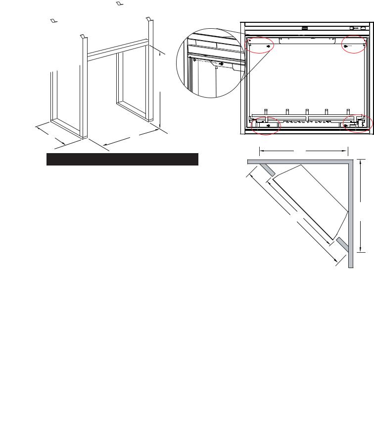
Prepare rough in framing following the recommended dimensions in Figure 1. For the corner rough in |
|
|
||||||||||||||||
|
framing, follow the recommended dimension in Figure 3. |
|
|
|
|
|
|
|
|
EN |
|||||||||
|
Select a location that is not prone to moisture and is located at least 36" (914mm) away from combustible |
|
|||||||||||||||||
|
materials such as curtain drapes, furniture, bedding, paper etc. |
|
|
|
|
|
|
|
|
|
|||||||||
|
|
|
|
Fig. 1 |
|
|
|
|
|
Fig. 2 |
|
|
|||||||
|
|
|
|
|
|
|
|
|
|
|
|||||||||
|
|
|
|
|
|
|
|
|
|
|
|
|
|
|
|
|
|
|
|
|
|
|
|
|
|
|
|
|
|
|
|
|
|
|
|
|
|
|
|
|
|
|
|
|
|
|
|
|
|
|
|
|
|
|
|
|
|
|
|
|
|
|
|
|
|
|
|
|
|
|
|
|
|
|
|
|
|
|
|
|
|
|
|
|
|
|
|
|
|
|
|
|
|
|
|
|
|
|
|
|
|
|
|
|
|
|
|
|
|
|
|
|
|
|
|
|
|
|
|
|
|
|
|
|
|
|
|
|
|
|
|
|
|
|
|
|
|
|
|
|
|
|
|
|
|
|
|
|
|
|
|
|
|
|
|
|
|
|
|
|
|
|
|
|
|
|
|
|
|
|
|
|
|
|
|
|
|
|
|
|
|
|
|
|
|
|
|
|
|
|
|
|
|
|
|
|
|
|
|
|
|
|
|
|
|
|
|
|
|
|
|
|
|
|
|
|
|
|
|
|
|
|
|
|
|
|
|
|
|
|
|
|
|
|
|
|
|
|
|
C
A |
B |
|
NEFB33H |
NEFB40H |
A |
10" |
14 1/2" (368mm) |
|
(254mm) |
|
|
|
|
B |
33 1/4" (844mm) |
39 1/2" (1003mm) |
C |
28 3/8" (720mm) |
31 5/8" (801mm) |
J |
44 1/2" |
60 3/4" (1543mm) |
|
(1130mm) |
|
|
|
|
K |
31 1/2" |
43" (1092mm) |
|
(800mm) |
|
|
|
|
L |
31 1/2" |
43" (1092mm) |
|
(800mm) |
|
|
|
Fig. 3 |
|
K |
|
B |
L |
J |
|
A.Once the rough opening has been prepared, and the power has been routed to the right side of the recess, the appliance may be installed.
B.The electrical connection must be made prior to placing the appliance into position. (See "HARD WIRING INSTALLATION" section). Have two people lift the appliance up and insert into the opening of the wall.
C.To secure the appliance to the wall, remove the glass door (See "GLASS DOOR REMOVAL AND INSTALLATION" section) and log / grate / ember bed (See "LOG, GRATE AND EMBER BED ASSEMBLY REMOVAL" section).
D.Level the appliance and use the 4 screws (#8 x 1 1/4") provided to secure the appliance to the wall studs, refer to Figure 2.
E.Install the brick panels (see "BRICK PANEL INSTALLATION AND REMOVAL" section), log /grate and ember bed assembly and the glass door to the appliance.
NOTE : In order to avoid the possibility of exposed insulation or vapour barrier coming in contact with the appliance body, it is recommended that the walls of the appliance enclosure be "finished" (ie. drywall/sheetrock), as you would finish any other outside wall of a home. This will ensure that clearance to combustibles is maintained within the cavity.
W415-2165 / E / 02.23.17
10
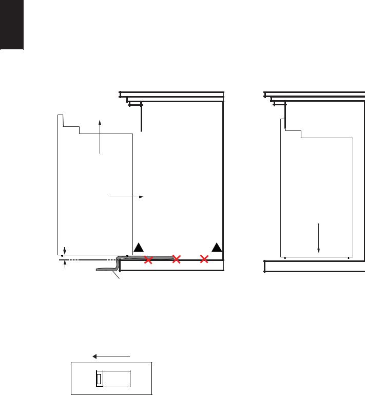
3.3.1APPLIANCE INSTALLATION
A.Place a cloth (not supplied) onto the mantel (Fig. 1) to prevent the appliance from scratching the
EN |
mantel surface. |
B.With two people, lift the appliance up and insert into the opening, leave space between the appliance and floor base in order to not scratch the floor surface. Do not push or slide the bottom of the appliance on the floor base (Fig. 1).
C.Set the appliance down and into place and remove the cloth (Fig. 2).
Fig. 1 |
Fig. 2 |
|
STEP 1: LIFT |
|
|
|
APPLIANCE |
|
|
APPLIANCE |
|
|
|
|
|
|
STEP 2: INSERT |
|
|
|
|
STEP 3: SET APPLIANCE |
LEAVE ABOUT |
|
|
|
A 1/4" GAP |
! |
DO NOT SLIDE APPLIANCE |
! |
|
|||
1/4" |
|
|
|
CLOTH |
|
|
|
3.3.2 VOLTAGE SELECTION
This appliance is able to use 120 volt or 240 volt power supply by setting the voltage selector switch (Fig. 1) and hard wiring configurations. NOTE : the factory set up configuration is 120 volt operation with cord plug.
Fig.1
IMPORTANT: Only a qualified person can change the voltage setting.
230
W415-2165 / E / 02.23.17
11
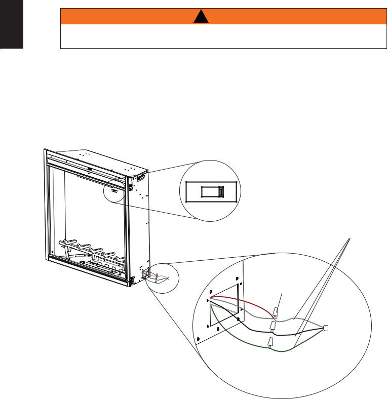
3.3.3 VOLTAGE SELECTOR SWITCH LOCATION
WARNING: The voltage selector switch must match the incoming power supply voltage. The heater will overheat if the switch does not match the incoming power supply voltage.
EN
CAUTION: When changing the voltage selector switch from 240 volts to 120 volts (or vice versa) the power supply must be turned off first.
The voltage selector switch is located inside the appliance (Fig. 1).
Fig.1
230 |
Voltage Selector Switch |
A.Remove the door, refer to "DOOR REMOVAL" section.
B.Remove metal cover from the voltage selector switch.
C.Change the voltage selector switch position. NOTE : Factory default setting is 120 volt (115 printed on the switch) if you use 120 volt power supply you do not need to make the changes.
When wiring the appliance for 240 volt the voltage selector switch should be in 230 volt position on the switch.
3.3.4 120 VOLT CORD PLUG INSTALLATION
The factory default setting is 120 volt cord plug installation configuration. Simply plug the appliance to a grounded 120V 15 Amp outlet box.
NOTE: Must be connected to a dedicated 15 Amp circuit. The use of an extension cord is NOT permitted.
W415-2165 / E / 02.23.17
12
3.3.5120V HARD WIRING INSTALLATION
! WARNING
EN
TURN OFF THE APPLIANCE COMPLETELY AND LET COOL BEFORE SERVICING. ONLY A QUALIFIED
SERVICE PERSON SHOULD SERVICE AND REPAIR THIS ELECTRIC APPLIANCE.
120V HARD WIRING CONNECTION
If it is necessary to hard wire this appliance, a qualified electrician must remove the cord connection, and wire the appliance directly to the household wiring. The wire and power supply breaker must be rated for 120V minimum 15 Amps.
This appliance must be electrically connected and grounded in accordance with local codes, if hard wired. In the absence of local codes, use the current CSA C22.1 CANADIAN ELECTRICAL CODE in Canada or the current ANSI/NFPA 70 NATIONAL ELECTRICAL CODE in the United States.
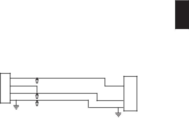
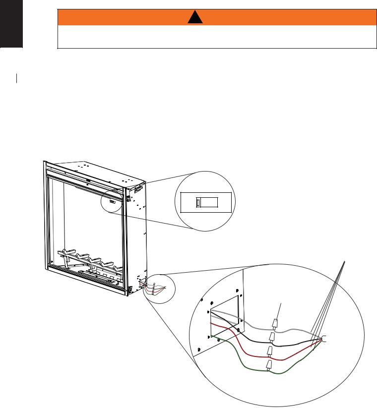
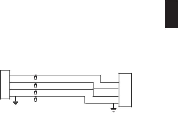
NOTE: There are 4 wires from the fireplace junction; white (neutral), black (power L1), Red (Power L2) and green (ground) that connect to 120V power supply (breaker panel).
Voltage Selector Switch
115
White, Green and Black wires:
Connect to 120V power supply.
RED |
WHITE (N) |
|
WHITE |
||
BLACK (L1) |
||
BLACK |
GREEN (G) |
|
GREEN |
|
Wire Nut |
|
|
RED |
WHITE (N) |
|
WHITE |
||
BLACK (L1) |
||
|
||
BLACK |
GREEN (G) |
|
GREEN |
|
W415-2165 / E / 02.23.17
13
A.Remove the securing screw from the electrical cover plate, located on the right hand side of the fireplace.
B.Add an electrical box connector and feed the supply wires through the 7/8" (22mm) knock out.
EN
C. Separate the black, white, red and green wires that have the wire nuts on them.
D. Remove the wire nuts and secure the black wire (L1) to the black (L1) lead of the power supply. Connect the white wire and red wire from the unit to the white (N) wire from the power supply. Connect the green wire to the ground wire.
E. Resecure the cover plate.
F. Locate the voltage selector switch inside the appliance and remove the 2 screws on the metal cover.
G. Ensure that the switch is switched to 120 volt position (115 is printed on the switch). Reinstall the metal cover.
' |
+ |
BLACK (L1) |
|
120V |
|
* |
|
|
|
||
3 |
6 |
RED (L2) |
BLACK (L1) |
|
4 |
& |
/ |
1 |
|||
1 |
$ |
WHITE (N) |
|
6 |
|
- |
5 |
|
0 |
1 |
|
" |
* |
GREEN (G) |
WHITE (N) |
8 |
1 |
$ |
0 |
& |
- |
||
& |
/ |
WIRE NUT |
GREEN(G) |
3 |
: |
NOTE: Leave enough wire so that the appliance can be removed from the enclosure without disconnecting the power supply.
W415-2165 / E / 02.23.17
14
3.3.6240V HARD WIRING INSTALLATION
! WARNING
EN
TURN OFF THE APPLIANCE COMPLETELY AND LET COOL BEFORE SERVICING. ONLY A QUALIFIED
SERVICE PERSON SHOULD SERVICE AND REPAIR THIS ELECTRIC APPLIANCE.
240V HARD WIRING CONNECTION
If it is necessary to hard wire this appliance, a qualified electrician must remove the cord connection, and wire the appliance directly to the household wiring. The wire and double-pole power supply breaker must rated for 240V minimum 15 Amps, maximum 20 Amps.
This appliance must be electrically connected and grounded in accordance with local codes, if hard wired. In the absence of local codes, use the current CSA C22.1 CANADIAN ELECTRICAL CODE in Canada or the current ANSI/NFPA 70 NATIONAL ELECTRICAL CODE in the United States.
NOTE: There are 4 wires from the fireplace junction; white (neutral), black (power L1), Red (Power L2) and green (ground) that connect to 240V double-pole power supply (breaker panel).
Voltage Selector Switch
230
White, Black, Red and Green wires:
Connect to 240V power supply.
WHITE |
WHITE (N) |
BLACK |
BLACK (L1) |
|
RED (L2) |
RED |
GREEN (G) |
GREEN |
|
Wire Nut |
|
WHITE |
WHITE (N) |
|
|
BLACK |
BLACK (L1) |
|
RED (L2) |
RED |
GREEN (G) |
GREEN |
|
W415-2165 / E / 02.23.17
15
A.Remove the securing screw from the electrical cover plate, located on the right hand side of the fireplace.
B.Add an electrical box connector and feed the supply wires through the 7/8" (22mm) knock out.
C. |
Separate the black, white, red and green wires that have the wire nuts on them. |
EN |
|
D.Remove the wire nuts and secure the black wire (L1) to the black (L1) lead of the power supply. Connect the red wire (L2) to the red wire (L2) of the power supply. Connect the white wire from the unit to the white (N) wire from the power supply. Connect the green wire to the ground wire.
E.Resecure the cover plate.
F.Locate the voltage selector switch inside the appliance. Remove the 2 screws on the metal cover.
G.Ensure that the switch is switched to 240 volt position (230 is printed on the switch). Reinstall the metal cover.
' |
+ |
BLACK (L1) |
|
240V |
|
* |
|
|
|
||
3 |
6 |
RED (L2) |
BLACK (L1) |
|
4 |
& |
/ |
1 |
|||
1 |
$ |
WHITE (N) |
RED (L2) |
6 |
|
- |
5 |
0 |
1 |
||
" |
* |
GREEN (G) |
WHITE (N) |
8 |
1 |
$ |
0 |
& |
- |
||
& |
/ |
WIRE NUT |
GREEN(G) |
3 |
: |
NOTE: To aid with moving the appliance, leave enough wire so that the appliance can be removed from the enclosure without disconnecting the power supply. If servicing, shut off power supply.
W415-2165 / E / 02.23.17
16
4.0 OPERATING INSTRUCTIONS
|
Once the appliance has been plugged into a grounded electrical outlet or hard wired to a dedicated 120V or |
EN |
240V power supply, it is ready to operate. |
|
NOTE: Ensure the house circuit breakers for the power supply are turned on. |
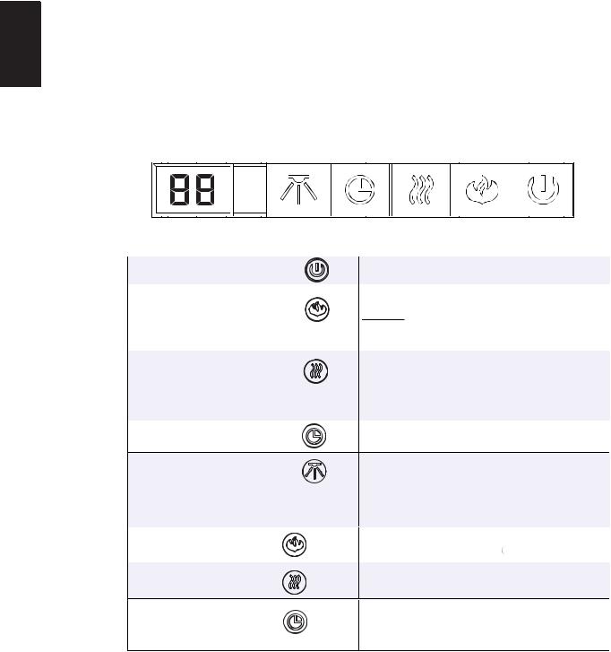
4.1 OPERATING CONTROL PANEL
The Control Panel is located on the top front of the appliance.
POWER
FLAME & EMBER LIGHT
CONTROL
HEATER CONTROL
TIMER
DECORATIVE LIGHT
F° / C° SWITCH |
Hold 5 |
|
seconds |
||
|
||
HEATER LOCK |
Hold 5 |
|
|
seconds |
|
TEMPERATURE |
Hold 5 |
|
CONTROL |
seconds |
|
|
Turns the appliance ON/OFF.
Controls Flame brightness and the Ember Light.
5 Settings: Flame & Ember off (FO), Ember and log on but Flame off (LL), small Flame & Ember (F1), medium Flame & Ember (F2), brightest Flame and Ember (F3).
Turns the Heater and Blower ON/OFF.
3 Settings: Heater & Blower off (HO), Blower on (BL), heater and blower on (H1).
Timer can be programed to run appliance for specific lengths of time (30mins. minimum to 6hrs maximum).
Controls Decorative Light settings.
4 Settings: Decorative Light off (do), white colour (d1), auto-cycle from White / Orange / Blue / Orange-Blue / White-Orange / White-Blue (d2), lock to desired colour (d3). It will take 8.5 seconds to switch between colours (on d2 setting).
To change temperature format, Fahrenheit or Celsius. Press and hold the Flame button for 5 seconds.
Heater button can be locked or unlocked by holding the Heater button for 5 seconds.
Press and hold the Timer button for 5 seconds. This will change the button to Temperature Control, or vice versa. There are 7 temperature settings (61°F, 64°F, 70°F, 75°F, 81°F, 85°F and OFF)
W415-2165 / E / 02.23.17
17
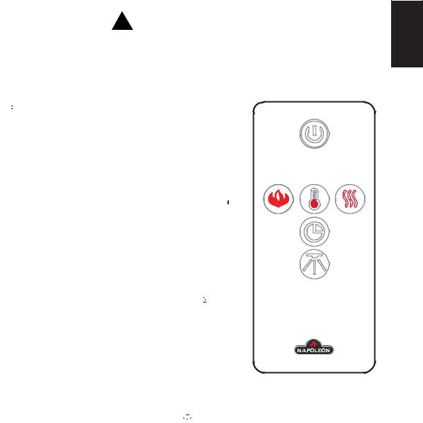
4.2 OPERATING BY REMOTE CONTROL
! WARNING |
|
EN |
TO AVOID DANGER OF SUFFOCATION KEEP THE PACKAGING BAG AWAY FROM BABIES AND |
|
|
|
|
|
CHILDREN. DO NOT USE IN CRIBS, BED, CARRIAGES OR PLAY PENS. THIS BAG IS NOT A TOY. |
|
|
KNOT BEFORE THROWING AWAY. |
|
|
|
|
|
NOTE: When operating the remote control, it must be directed towards the front center of the appliance.
A.The power button can be used to turn the appliance on/off. Pressing this button  activates the power to the appliance. Pressing the power button again will turn off the appliance. The ember and log
will fade 4 seconds after turning off the appliance.
B.To adjust the flame brightness and ember log light, press the flame button  . There is one ember log light and three flame brightness levels to cycle through and then an off setting ( LL, F1, F2, F3 and then F0).F3 is the brightest flame level, LL is the ember log light only.
C. To control the thermostat function, press the thermostat button  . There are 7 temperature settings (61°F, 64°F, 70°F, 75°F, 81°F 85°F and off). The default setting will display Fahrenheit. Press the thermostat button to cycle through the settings. Once you have selected the desired temperature, the heater will automatically operate until that temperature is reached. When the room temperature is 2 degrees lower than the temperature setting, the heater will turn on.
D.To activate the heater and blower, press the heater button 

 , the blower will turn on. Press the heater button again to turn on the heater and blower. Press the heater button again to turn off the heater and blower.
E. The timer controls all operating modes of the appliance. To activate the timer, press the timer button  . To choose the desired time, continue to press the timer button. There are 8 settings (30mins,1h, 2h, 3h, 4h, 5h, 6h and off). The fireplace will turn off at the setting time.
F.To activate the decoration light, press the light button  .There are three settings to cycle through and then an off setting (d1, d2, d3 and then d0). d1 white colour, d2 colour cycles from White / Orange / Blue / Orange-Blue / White-Orange / White-Blue. It will take 8.5 seconds to switch from one colour to the next when in d2 setting and d3 will lock to a desired colour.
G.To turn off the appliance, press the power button once on the remote, or press the power button once on the control panel on the unit.
NOTE: This hand held remote control must remain within 6 meters or 19 feet of the appliance to be effective.
W415-2165 / E / 02.23.17
18 |
|
|
|
|
5.0 |
FINISHING |
|
|
|||
EN |
|
|
! WARNING |
|
|
|
POWER SUPPLY SERVICE MUST BE COMPLETED PRIOR TO FINISHING TO AVOID |
|
|
|
RECONSTRUCTION. |
|
|
|
|
|
|
|
HEAT VENTS AND AIR OPENINGS CANNOT BE COVERED IN ANY CIRCUMSTANCES. |
|
|
|
|
5.1BRICK PANEL INSTALLATION AND REMOVAL
A.Slide the panels into place and secure it using the 2 screws provided (#6 x 3/8").
B.Ensure the brick panels are positioned properly in the unit and are not angled or sticking out from the unit.
C.To remove the panels, remove the 2 screws.
2 SCREW LOCATIONS
W415-2165 / E / 02.23.17
19
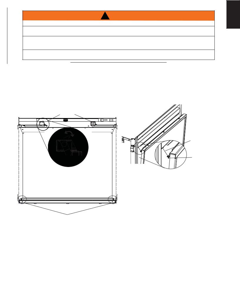
5.2GLASS DOOR INSTALLATION
! WARNING |
EN |
|
GLASS MAY BE HOT, DO NOT TOUCH GLASS UNTIL COOLED.
IF EQUIPPED WITH DOOR LATCHES THAT ARE PART OF A SAFETY RELIEF SYSTEM, THEY MUST BE PROPERLY ENGAGED. DO NOT OPERATE THE APPLIANCE WITH LATCHES DISENGAGED.
FACING AND/OR FINISHING MATERIALS MUST NOT INTERFERE WITH AIR FLOW THROUGH AIR OPENINGS, LOUVRE OPENINGS, OPERATION OF LOUVRES OR DOORS OR ACCESS FOR SERVICE. OBSERVE ALL CLEARANCES WHEN APPLYING COMBUSTIBLE MATERIALS.
BEFORE DOOR IS REMOVED TURN THE APPLIANCE OFF AND WAIT UNTIL APPLIANCE IS COOL TO
THE TOUCH. DOORS ARE HEAVY AND FRAGILE SO HANDLE WITH CARE.
47.1
A.To install the glass door, simply place the door on the holding pins on the bottom frame of the unit. Install the screw into the safety catch wire, slightly push the glass door into the frame and latch it secure with the two top latches.
B.To remove the glass door, swing the top two latches to release the door. The door will hang slightly on the the safety catch wire. NOTE: Pushing in on the door will make the latch swing easier.
C.Place one hand on the glass door while removing the screw from the catch wire. Allow the door to pivot slightly, hold the sides with both hands while lifting the door out of the unit.
LATCH |
|
OPEN |
|
LOCK |
SAFETY |
|
CATCH WIRE |
|
SCREW |
PIN HOLE
* ILLUSTRATED WITH LATCHES VISIBLE
W415-2165 / E / 02.23.17
|
20 |
|
6.0 MAINTENANCE |
EN |
! WARNING |
PREPARATION FOR MAINTENANCE
ALWAYS DISCONNECT THE POWER AND ALLOW THE ELECTRIC APPLIANCE TO COOL BEFORE PERFORMING ANY CLEANING, MAINTENANCE OR RELOCATION OF THIS ELECTRIC APPLIANCE.
TURN CONTROLS TO OFF AND REMOVE PLUG FROM OUTLET OR TURN OFF THE HOUSE
CIRCUIT BREAKER TO ELECTRIC APPLIANCE RECEPTACLE.
DO NOT INSTALL REPLACEMENT LED LIGHTS THAT EXCEED SPECIFIED MAXIMUM WATTS.
! IMPORTANT SAFETY INFORMATION !
CONSUMER: Read this first before attempting to service this appliance. For your safety, always comply with all warnings and safety instructions to prevent personal injury or property damage.
!NOTE: Only a qualified service technician or service agency should service this electric appliance.
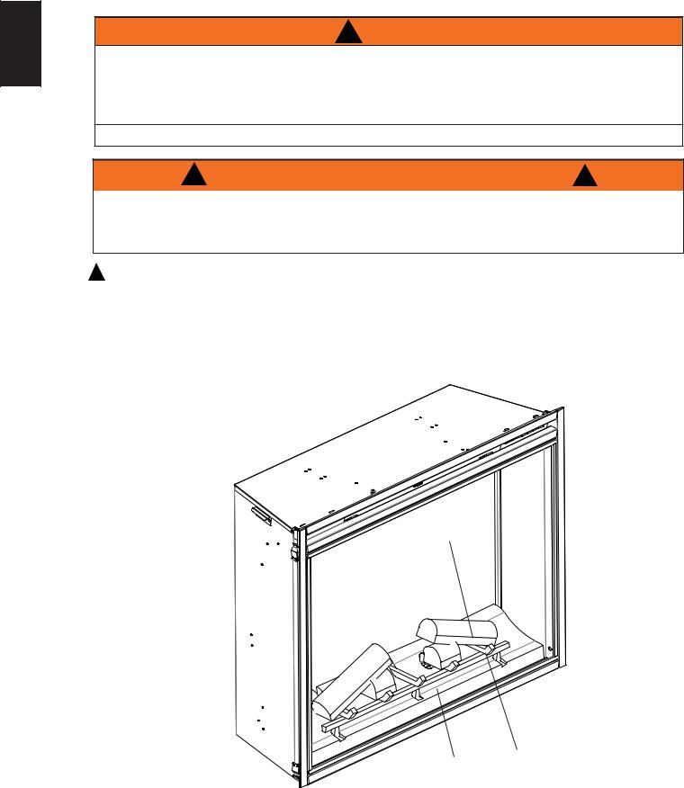
6.1LOG, GRATE AND EMBER BED ASSEMBLY REMOVAL
A.Cut zip-ties securing log assembly to appliance and remove the card board holding the logs, grate and ember bed assembly to the appliance.
B.Pinch the back of the assembly and lift it up from the appliance.
LOGS
GRATE
EMBER
BED
W415-2165 / E / 02.23.17

6.2FLAME PANEL REMOVAL
A.Remove the 4 screws securing the top bracket.
B.Remove the 2 screws securing the left bracket, repeat for the right side.
C.Lift up and remove the panel.
6.3FLAME BOARD REMOVAL
A. Remove the 3 screws on the bottom and 4 screws on top of the flame board.
B.Lift the flame board out of the unit.
21
EN
W415-2165 / E / 02.23.17
 Loading...