


Napoleon GL32P, GL32N, GL28P, GL28N, GL22P Installation Manual
...INSTALLER: LEAVE THIS MANUAL WITH THE APPLIANCE.
CONSUMER: RETAIN THIS MANUAL FOR FUTURE REFERENCE.
NEVER LEAVE CHILDREN OR OTHER AT RISK INDIVIDUALS ALONE WITH THE APPLIANCE.
INSTALLATION AND
OPERATING INSTRUCTIONS
CERTIFIED UNDER: ANSI Z21.60 / CSA 2.26 DECORATIVE GAS APPLIANCES FOR INSTALLATION IN SOLID-FUEL BURNING APPLIANCES
GL22N, GL28N, GL32N
NATURAL GAS
GL22P, GL28P, GL32P
PROPANE
CERTIFIED FOR CANADA AND UNITED STATES USING ANSI/CSA METHODS. |
|
SAFETY INFORMATION |
GL2 |
|
! WARNING
If the information in these instructions are not followed exactly, a fire or explosion may result causing property damage, personal injury or loss of life.
- Do not store or use gasoline or other flammable vapors and liquids in the vicinity of this or any
other appliance. GL28 - WHAT TO DO IF YOU SMELL GAS:
• Do not try to light any appliance.
• Do not touch any electrical switch; do not use any phone in your building.
• Immediately call your gas supplier from a neighbour’s phone. Follow the gas supplier’s instructions.
• If you cannot reach your gas supplier, call the fire department.
- Installation and service must be performed by a qualified installer, service agency or the supplier.
This appliance may be installed in an aftermarket, permanently located, manufactured home (USA only) or mobile home, where not prohibited by local codes.
This appliance is only for use with the type of gas indicated on the rating plate. This appliance is not convertible for use with other gases, unless a certified kit is used.
GL32
C E R T I F I E D
Wolf Steel Ltd., 24 Napoleon Rd., Barrie, ON, L4M 0G8 Canada /
103 Miller Drive, Crittenden, Kentucky, USA, 41030
Phone (705)721-1212 • Fax (705)722-6031 • www.napoleonfireplaces.com • ask@napoleonproducts.com
EN
FR PG 29
$10.00 |
|
1.33 |
W415-1101 / B / 07.29.13 |
2
EN
TABLE OF CONTENTS
INSTALLATION OVERVIEW |
2 |
INTRODUCTION |
3 |
DIMENSIONS |
4 |
GENERAL INSTRUCTIONS |
5 |
GENERAL INFORMATION |
6 |
MINIMUM FIREPLACE CAVITY SIZE |
6 |
RATING PLATE |
6 |
INSTALLATION |
7 |
BATTERY INSTALLATION |
7 |
GAS PIPING AND BURNER PLACEMENT |
8 |
DAMPER STOP INSTALLATION |
9 |
FINISHING |
10 |
SAND OR GLASS MEDIA PLACEMENT |
10 |
GRATE INSTALLATION |
10 |
CHARCOAL LUMPS/EMBERS |
10 |
LOG PLACEMENT |
11 |
GL22 |
11 |
GL28 |
12 |
GL32 |
12 |
MOBILE HOME INSTALLATION |
13 |
OPTIONAL REMOTE INSTALLATION (NOT SUPPLIED) |
13 |
WIRING DIAGRAM |
14 |
OPERATION |
15 |
OPERATING AND LIGHTING INSTRUCTIONS |
15 |
ADJUSTMENTS |
16 |
PILOT BURNER ADJUSTMENT |
16 |
FLAME CHARACTERISTICS |
16 |
MAINTENANCE |
17 |
BATTERY REPLACEMENT |
17 |
REPLACEMENTS |
18 |
TROUBLESHOOTING |
21 |
WARRANTY |
23 |
SERVICE HISTORY |
24 |
NOTES |
25 |
NOTE: Changes, other than editorial, are denoted by a vertical line in the margin.
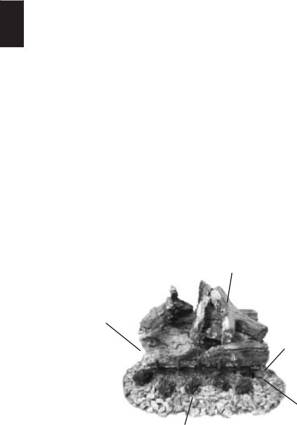
1.0 INSTALLATION OVERVIEW
Logs, see “LOG PLACEMENT” section.
Burner, see “GAS PIPING” section.
Grate, see “GRATE 
INSTALLATION” section.
Media, see “Sand or Glass
MEDIA PLACEMENT” section.
Rating Plate, see “RATING PLATE INFORMATION” section.
Batteries, see “BATTERY INSTALLATION” and “BATTERY REPLACEMENT” section.
W415-1101 / B / 07.29.13

3
2.0 INTRODUCTION
! WARNING |
EN |
|
•THIS APPLIANCE IS HOT WHEN OPERATED AND CAN CAUSE SEVERE BURNS IF CONTACTED.
•ANY CHANGES OR ALTERATIONS TO THIS APPLIANCE OR IT’S CONTROLS CAN BE DANGEROUS AND IS PROHIBITED.
•Do not operate appliance before reading and understanding operating instructions. Failure to operate appliance according to operating instructions could cause fire or injury.
•Risk of fire or asphyxiation do not operate appliance with fixed glass removed.
•Do not connect 110 volts to the control valve.
•Risk of burns. The appliance should be turned off and cooled before servicing.
•Do not install damaged, incomplete or substitute components.
•Risk of cuts and abrasions. Wear protective gloves and safety glasses during installation. Sheet metal edges may be sharp.
•Do not burn wood or other materials in this appliance.
•Children and adults should be alerted to the hazards of high surface temperature and should stay away to avoid burns or clothing ignition. Toddlers, young children and others may be susceptible to accidental contact burns. A physical barrier is recommended if there are at risk individuals in the house. To restrict access to an appliance or stove, install an adjustable safety gate to keep toddlers, young children and other at risk individuals out of the room and away from hot surfaces.
•Clothing or other flammable material should not be placed on or near the appliance.
•Due to high temperatures, the appliance should be located out of traffic and away from furniture and draperies.
•Ensure you have incorporated adequate safety measure to protect infants/toddlers from touching hot surfaces.
•Even after the appliance is out, the glass and/or screen will remain hot for an extended period of time.
•Check with your local hearth specialty dealer for safety screens and hearth guards to protect children from hot surfaces. These screens and guards must be fastened to the floor.
•Any safety screen or guard removed for servicing must be replaced prior to operating the appliance.
•This appliance is a vented gas-fired appliance. Do not burn wood or other materials in this appliance.
•It is imperative that the control compartments, burners and circulating blower and its passageway in the appliance and venting system are kept clean. The appliance and its venting system should be inspected before use and at least annually by a qualified service person. More frequent cleaning may be required due to excessive lint from carpeting, bedding material, etc. The appliance area must be kept clear and free from combustible materials, gasoline and other flammable vapors and liquids.
•Under no circumstances should this appliance be modified.
•This appliance must not be connected to a chimney flue pipe serving a separate solid fuel burning appliance.
•Do not use this appliance if any part has been under water. Immediately call a qualified service technician to inspect the appliance and to replace any part of the control system and any gas control which has been under water.
•Do not operate the appliance with the glass door removed, cracked or broken. Replacement of the glass should be done by a licensed or qualified service person.
•Do not strike or slam shut the appliance glass door.
•Only doors / optional fronts certified with the unit are to be installed on the appliance.
•Keep the packaging material out of reach of children and dispose of the material in a safe manner. As with all plastic bags, these are not toys and should be kept away from children and infants.
•As with any combustion appliance, we recommend having your appliance regularly inspected and serviced as well as having a Carbon Monoxide Detector installed in the same area to defend you and your family against Carbon Monoxide.
•Ensure clearances to combustibles are maintained when building a mantel or shelves above the appliance. Elevated temperatures on the wall or in the air above the appliance can cause melting, discolouration or damage to decorations, a T.V. or other electronic components.
3.16B
W415-1101 / B / 07.29.13
4
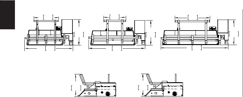
2.1DIMENSIONS
GL22 |
|
EN |
270mm |
11” |
|
|
113/8” |
|
289mm |
211/2” |
546mm |
|
GL22 |
GL28 |
101/2” |
GL32 |
|
|
161/8” |
||
|
267mm |
410mm |
|
|
113/8” |
|
113/8” |
|
289mm |
|
289mm |
27” |
686mm |
32” |
813mm |
|
GL28 / GL32 |
|
|
611/16” |
67/8” |
170mm |
175mm |
W415-1101 / B / 07.29.13
5
2.2GENERAL INSTRUCTIONS
! WARNING |
EN |
ALWAYS LIGHT THE PILOT WHETHER FOR THE FIRST TIME OR IF THE GAS SUPPLY HAS RUN OUT,
WITH THE GLASS DOOR OPENED OR REMOVED.
PROVIDE ADEQUATE CLEARANCE FOR SERVICING AND OPERATING THE APPLIANCE.
PROVIDE ADEQUATE VENTILATION.
NEVER OBSTRUCT THE FRONT OPENING OF THE APPLIANCE.
OBJECTS PLACED IN FRONT OF THE APPLIANCE MUST BE KEPT A MINIMUM OF 48” FROM THE
FRONT FACE OF THE UNIT.
SURFACES AROUND AND ESPECIALLY ABOVE THE APPLIANCE CAN BECOME HOT. AVOID CONTACT
WHEN THE APPLIANCE IS OPERATING.
FIRE RISK. EXPLOSION HAZARD.
HIGH PRESSURE WILL DAMAGE VALVE. DISCONNECT GAS SUPPLY PIPING BEFORE PRESSURE TESTING GAS LINE AT TEST PRESSURES ABOVE 1/2 PSIG. CLOSE THE MANUAL SHUT-OFF VALVE BEFORE PRESSURE TESTING GAS LINE AT TEST PRESSURES EQUAL TO OR LESS THAN 1/2 PSIG.
USE ONLY WOLF STEEL APPROVED OPTIONAL ACCESSORIES AND REPLACEMENT PARTS WITH THIS APPLIANCE. USING NON-LISTED ACCESSORIES (BLOWERS, DOORS, LOUVRES, TRIMS, GAS COMPONENTS, VENTING COMPONENTS, ETC.) COULD RESULT IN A SAFETY HAZARD AND WILL VOID THE WARRANTY AND CERTIFICATION.
DO NOT USE A BLOWER INSERT, HEAT EXCHANGER INSERT OR ANY OTHER ACCESSORY NOT APPROVED FOR USE
WITH THIS APPLIANCE
Thoroughly clean the chimney, flue and existing appliance |
We suggest that our gas |
|
before installing the new appliance into it. Do not burn solid |
||
fuels in any appliance that is equipped with this gas log set. |
hearth products be installed |
|
The installation of this appliance must conform with local |
and serviced by professionals |
|
codes or in the absence of local codes, it must conform |
who are certified in the U.S. |
|
to ANSI Z.223.1/NFPA 54 or the CAN/CGA B149. The |
by the National Fireplace |
|
installation and the provisions for combustion and |
Institute® (NFI) as NFI Gas |
|
ventilation air must conform with the National Fuel Gas |
||
Specialists |
||
Code, ANSI Z223.1/NFPA 54, or the CSA B149.1, Natural |
||
Gas and Propane Installation Code. The installation of |
www.nficertified.org |
|
|
appliances designed for manufactured home (U.S. only) or mobile home installation must conform with the Standard CAN/CSA Z240 MH, Mobile Housing, in Canada, or with the Manufactured Home Construction and Safety Standard, Title 24 CFR, Part 3280, in the United States, or when such a standard is not applicable, ANSI/NCSBCS A225.1/NFPA 501A, Manufactured Home Installations Standard.
Do not operate appliance in the presence of gasoline or other flammable liquids and vapours. Keep area clear of other combustible materials. The appliance and its shut off must be disconnected from the gas supply piping system before any pressure testing of the system is done.
Installation practices vary from region to region and it is important to know the specifics that apply to your area,
For example: in Massachusetts State:
•This product must be installed by a licensed plumber or gas fitter when installed within the commonwealth of Massachusetts.
•The appliance damper must be removed or welded in the open position prior to installation of a appliance insert or gas log.
•The appliance off valve must be a “T” handle gas cock.
•The flexible connector must not be longer than 36” (914.4mm).
•The appliance is not approved for installation in a bedroom or bathroom unless the appliance is a direct vent sealed combustion product.
•A carbon monoxide detector is required in all rooms containing gas fired appliances.
No external electricity (110 volts or 24 volts) is required for the gas system operation.
W415-1101 / B / 07.29.13
6
2.3 GENERAL INFORMATION
|
|
|
|
|
|
|
|
|
EN |
|
|
! |
WARNING |
|
|
|
|
|
THIS APPLIANCE MUST NOT BE INSTALLED IN A BEDROOM OR BATHROOM. |
|
||||||
|
|
|
|
|
|
|
|
|
|
|
|
GL22 |
GL28 |
GL32 |
|||
|
|
|
NG |
LP |
NG |
LP |
NG |
LP |
|
|
|
||||||
|
|
Altitude (FT) |
0-4,500 |
0-4,500 |
0-4,500 |
0-4,500 |
0-4,500 |
0-4,500 |
|
|
Max input (BTU/HR) |
70,000 |
50,000 |
80,000 |
65,000 |
90,000 |
65,000 |
|
|
Min Inlet Gas Supply Pressure |
4.5“ InWc |
11“ InWc |
4.5“ InWc |
11“ InWc |
4.5“ InWc |
11“ InWc |
|
|
|
(11.2mb) |
(27.4mb) |
(11.2mb) |
(27.4mb) |
(11.2mb) |
(27.4mb) |
|
|
Max Inlet Gas Supply Pressure |
7“ InWc |
13“ InWc |
7“ InWc |
13“ InWc |
7“ InWc |
13“ InWc |
|
|
|
(17.4mb) |
(32.4mb) |
(17.4mb) |
(32.4mb) |
(17.4mb) |
(32.4mb) |
|
|
Manifold Pressure (Under Flow |
3.5“ InWc |
10“ InWc |
3.5“ InWc |
10“ InWc |
3.5“ InWc |
10“ InWc |
|
|
Conditions) |
(8.7mb) |
(25mb) |
(8.7mb) |
(25mb) |
(8.7mb) |
(25mb) |
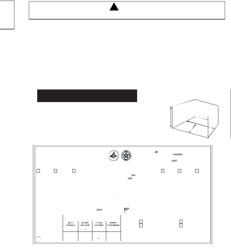
2.4MINIMUM FIREPLACE CAVITY SIZE
|
HEIGHT |
REAR WIDTH |
DEPTH |
LOG SET |
A |
B |
C |
GL22 |
20” |
23” |
14” |
|
(508mm) |
(584.2mm) |
(355.6mm) |
GL28 |
20” |
29” |
14” |
|
(508mm) |
(736.6mm) |
(355.6mm) |
GL32 |
22” |
33” |
14” |
|
(558.8mm) |
(838.2mm) |
(355.6mm) |
Do not install the gas log set into a cavity smaller than that referenced in the table.
A 
B
C
CERTIFIED UNDER / HOMOLOGUE SELON |
LES NORMES: ANSI Z21.60-2003/CSA 2.26-2003 (R 2009), DECORATIVE APPLIANCE FOR INSTALLATION IN |
|
|
ID-FU L BURNING |
|
|||||||||||||||||||||||||||||||||||||||||||||||||
SOL |
|
|||||||||||||||||||||||||||||||||||||||||||||||||||||
WARNING: IMPROPER INSTALLATION, ADJUSTMENT, ALTERATION, SERVICE |
|
|
|
|
|
|
|
|
|
|
|
AVERTISS M |
|
|
|
|
|
|
|
|
|
|
||||||||||||||||||||||||||||||||
|
|
|
|
|
|
|
|
|
|
|
NT: |
UNE INSTALLATION |
|
|
|
CONFORME, DES AJUSTEMENTS, |
||||||||||||||||||||||||||||||||||||||
|
|
|
|
|
|
|
|
|
|
|
NON |
|||||||||||||||||||||||||||||||||||||||||||
OR MAINTENANCE CAN CAUSE INJURY OR PROPERTY DAMAGE. REFER TO THE |
|
|
|
|
|
|
|
|
|
|
|
DES ALTÉRATIONS, UN S RVIC |
OU UN NTR |
TI N INADÉQUATS PEUVENT CAUSER DES |
||||||||||||||||||||||||||||||||||||||||
OWNER’S INFORMATION MANUAL PROVIDED WITH THIS APPLIANCE. FOR |
|
|
|
|
|
|
|
|
|
|
|
|
|
|
|
|
|
|
|
|
|
|
|
|
|
|
|
|
|
|
|
|
||||||||||||||||||||||
|
|
|
|
|
|
|
|
|
|
|
DOMMAGES MATÉRI LS OU D S BL SSUR S |
CORPOR |
|
LLES. RÉFÉREZ-VOUS AU |
||||||||||||||||||||||||||||||||||||||||
|
|
|
|
|
|
|
|
|
|
|
|
|||||||||||||||||||||||||||||||||||||||||||
ASSISTANCE OR ADDITIONAL INFORMATION, CONSULT A QUALIFIED INNSTALLER, |
|
|
|
|
|
|
|
|
|
|
|
|
|
|
|
|
|
|
|
|
|
|
|
|
|
|
|
|
||||||||||||||||||||||||||
|
C E RT I F I E D |
|
|
|
|
|
MANUEL D’INSTRUCTIONS FOURNI AV C C T |
APPAR |
IL. POUR DE L’ASSISTANCE OU |
|||||||||||||||||||||||||||||||||||||||||||||
SERVICE AGENCY OR THE GAS SUPPLIER. |
|
|
|
|
|
|
|
|
|
|
|
|
|
|
|
|
|
|
|
|
|
|
|
|
|
|
|
|
|
POUR P US D’INFORMATION, CONSU T Z UN |
INSTALLAT UR QUALIFIÉ, UNE AGENCE |
|||||||||||||||||||||||
NATURAL GAS MODELS |
|
|
|
|
|
|
|
|
|
|
|
|
|
|
|
|
|
|
|
|
|
|
|
|
|
|
|
|
|
D’ENTRETIEN OU FOURNISS UR D GAZ. |
|
PROPANE MODELS |
||||||||||||||||||||||
|
|
|
|
|
|
|
|
|
|
|
|
|
|
|
|
|
|
|
|
|
|
|
|
|
|
|
|
|
|
|
|
|
|
|
|
|
|
|
|
|||||||||||||||
GL22N |
GL28N |
|
|
|
GL32N |
|
|
|
|
|
|
|
|
|
|
|
|
|
|
|
|
|
|
|
|
|
|
|
|
|
|
|
|
|
|
|
|
GL22P |
|
|
|
|
|
|
|
|
GL28P |
GL32P |
||||||
|
|
|
|
|
|
|
|
|
|
|
|
|
|
|
|
|
|
|
|
|
|
|
|
|
|
|
|
|
|
|
|
|
|
|
|
|
|
|
|
|
|
|
||||||||||||
|
|
|
|
|
|
|
|
|
|
|
|
|
|
|
|
|
|
|
|
|
|
|
|
|
|
|
|
|
|
|
|
|
|
|
|
|
|
|||||||||||||||||
70,000BTU/h |
80,000BTU/h |
|
90,000BTU/h |
|
|
|
|
|
|
|
|
|
|
|
|
|
|
INPUT / ALIMENTATION |
|
|
|
|
|
50,000BTU/h |
|
|
|
65,000BTU/h |
65,000BTU/h |
|||||||||||||||||||||||||
|
|
|
|
|
|
|
|
|
|
|
|
|
|
|
|
|
|
|
|
|||||||||||||||||||||||||||||||||||
|
|
|
|
|
|
|
|
|
|
|
|
|
|
|
|
|
|
|
|
|
|
|
|
|
|
|
|
|
|
|
|
|
|
|
|
|
|
|
|
|
|
|
|
|
|
|
|
|
|
|
|
|
|
|
|
|
0-4500FT (0-1370m) |
|
|
|
|
|
|
|
|
|
|
|
|
ALTITUDE / ÉLÉVATION |
|
|
|
|
|
0-4500FT (0- |
1370m) |
|
|
|
|
|
|
||||||||||||||||||||||||||
3.5” WATER COLUMN/D’UNE COLONNE D’EAU |
|
|
|
|
|
|
MANIFOLD PRESSURE / |
|
RESSION AU CO ECTEUR |
10” WATER |
COLUMN/D’UNE COLONNE D’EAU |
|||||||||||||||||||||||||||||||||||||||||||
4.5” WATER COLUMN/D’UNE COLONNE D’EAU |
|
|
MINIMUM SUPPLY PRESSURE / |
RESSION D’ALIMENTATION MINIMALE |
11” WATER |
COLUMN/D’UNE COLONNE D’EAU |
||||||||||||||||||||||||||||||||||||||||||||||||
7.0” WATER COLUMN/D’UNE COLONNE D’EAU |
MAXIMUM SUPPLY PRESSURE / |
RESSION D’ALIMENTATION MAXIMALE |
13” WATER |
COLUMN/D’UNE COLONNE D’EAU |
||||||||||||||||||||||||||||||||||||||||||||||||||
WARNING: DO NOT ADD ANY MATERIAL TO THE APPLIANCE, WHICH WILL COME IN |
|
|
|
|
N’AJOUTEZ AUCUN MATÉRIAU À CET APPAREIL QUI ENTRERA EN |
|||||||||||||||||||||||||||||||||||||||||||||||||
|
|
AVERTISSEMENT: |
||||||||||||||||||||||||||||||||||||||||||||||||||||
CONTACT WITH THE FLAMES, OTHER THAN THAT SUPPLIED BY THE MANUFACTURER WITH THE |
|
|
CONTACT AVEC LES FLAMMES AUTRE QUE CELUI QUI EST FOURNI AVEC CET APPAREIL PAR LE |
|||||||||||||||||||||||||||||||||||||||||||||||||||
APPLIANCE. FOR ISNTALLATION IN A SOLD-FUEL BURNING FIREPLACE ONLY. |
|
|
|
|
|
|
|
|
FABRICANT. |
|
|
|
|
|
|
|
|
|
|
|
|
|
|
|
|
|||||||||||||||||||||||||||||
THE FIREPLACE CHIMNEY MUST HAVE A PERMANENT VENT OPENING TO AT OSPHERE OF NOT |
|
|
POUR INSTALLATION DANS UN FOYER Â COMBUSTIBLE SOLIDE SEULEMENT. |
|
||||||||||||||||||||||||||||||||||||||||||||||||||
LESS THAN 56.62” FOR GL22, 642” FOR GL28, 71.42” FOR GL32, OR AS DETER INED |
BY THE |
|
|
|
|
|
|
|
LA CHE INÉE DU FOYER DOIT POSSÉDER UN OUVERTURE D’ÉVACUATION PERMANENTE À L’AIR |
|||||||||||||||||||||||||||||||||||||||||||||
MANUFACTURER’S INSTALLATION INSTRUCTIONS. |
|
|
|
|
|
|
|
|
|
|
|
|
|
|
|
|
|
|
|
|
EXTÉRIEUR DE NON MOINS DE 56,62” POUR LE GL22, DE 642” POUR LE GL28 ET 71.42” POUR LE GL32 |
|||||||||||||||||||||||||||||||||
FOR YOUR SAFETY: DO NOT STORE OR USE GASOLINE OR OTHER FLA |
|
|
|
|
|
|
|
|
OU SELON LES INSTRUCTIONS D’INSTALATION DU FABRICANT. |
|
|
|
|
|
|
|||||||||||||||||||||||||||||||||||||||
ABLE |
|
|
|
|
|
OUR VOTRE SÉCURITÉ: N’ENTREPOSEZ PAS ET N’UTILISEZ PAS D’ESSENCE OU |
||||||||||||||||||||||||||||||||||||||||||||||||
VAPOURS AND LIQUIDS IN THE VICINITY OF THIS OR ANY OTHER APPLIANCE. |
|
|
|
|
|
|
|
|
|
|
|
|||||||||||||||||||||||||||||||||||||||||||
|
|
|
|
|
|
|
|
|
|
|
|
|
|
|
|
|
|
|
|
|
|
|
|
|
|
|
|
|
|
|
AUTRES LIQUIDES ET VAPEURS INFLAMMABLES À PROXIMITÉ DE CET OUT TOUT AUTRE |
|||||||||||||||||||||||
|
|
|
|
|
|
|
|
|
|
|
|
|
|
|
|
|
|
|
|
|
|
|
|
|
|
|
|
|
|
|
APPAREIL. |
|
|
|
|
|
|
|
|
|
|
|
|
|
|
|
|
|||||||
FOR MINIMUM CHIMNEY FLUE |
|
|
|
|
|
|
|
|
|
|
|
|
|
|
|
|
|
|
|
|
|
|
|
|
|
|
|
|
|
|
|
|
|
|
|
|
|
|
|
|
|
|
|
|
|
|
|
|
|
|
|
|
|
|
|
|
|
|
|
|
|
|
|
|
|
|
|
|
|
|
|
|
|
|
|
|
|
|
|
|
|
|
|
|
|
|
|
|
|
|
|
|
|
|
|
|
|
|
|
|
|
|
|
|
|
|
|
||
|
|
|
|
|
|
|
|
|
|
|
|
|
|
|
|
|
|
|
|
|
|
|
|
|
|
|
|
|
|
|
|
|
|
|
|
|
|
|
|
|
|
|
|
|
|
|
|
|
|
|
|
|
||
SEE INSTRUCTION MANUAL. |
|
|
|
|
|
|
|
|
|
|
|
|
|
|
|
|
|
|
|
|
|
|
|
|
|
|
|
|
|
|
|
(WSL) |
|
|
|
|
|
|
|
|
|
|
|
|
|
(NGZ) |
|
|||||||
POUR LES DIMENSIONS |
|
|
|
|
|
|
|
|
|
|
|
|
|
|
|
|
|
|
|
|
|
|
|
|
|
|
|
|
|
|
(NAC) |
|
|
|
|
|
|
|
|
|
|
|
|
|
(WUSA) |
|
||||||||
|
|
|
|
|
|
|
|
|
|
|
|
|
|
|
|
|
|
|
|
|
|
|
|
|
|
|
|
|
|
|
|
|
|
|
|
|
|
|
|
|
|
|
|
|||||||||||
MINIMALES DE LA CHEMINÉE, |
|
|
|
|
|
|
|
|
|
|
|
|
|
|
|
|
|
|
|
|
|
|
|
|
|
|
|
|
|
|
|
|
|
|
|
|
|
|
|
|
|
|
|
|
||||||||||
|
|
|
|
|
|
|
|
|
|
|
|
|
|
|
|
|
|
|
|
|
|
|
|
|
|
|
|
|
|
|
|
|
|
|
|
|
|
|
|
|
||||||||||||||
CONSULTEZ LE MANUEL |
GL22 |
|
|
|
|
|
|
|
|
|
|
|
|
|
|
|
|
14” |
|
|
|
|
|
|
|
|
|
|
|
|
|
|
|
|
|
|
|
|
|
|
|
|
|
|
|
|
||||||||
|
|
|
|
|
20” |
|
|
|
|
|
|
23”” |
|
|
|
|
|
|
|
|
|
|
|
|
|
|
|
|
|
|
|
|
|
|
|
|
|
|
|
|
|
|
|
|
|
|||||||||
D’INSTRUCTIONS |
|
|
GL28 |
|
|
|
|
|
|
|
|
|
|
|
|
|
|
|
|
|
|
|
14” |
|
|
|
|
|
WOLF STEEL LTD. |
|
|
|
|
|
|
|
|
|
|
|
|
|
|
|
|
|||||||||
|
|
|
|
|
|
|
|
20” |
|
|
|
|
|
|
2 |
9” |
|
|
|
|
|
|
|
24 NAPOLEON ROAD, BARRIE. ONTARIO L4M 0G8 CANADA |
|
|||||||||||||||||||||||||||||
|
|
|
|
|
|
|
|
|
|
|
|
|
|
|
|
|
|
|
|
|
|
|
|
14” |
|
|
|
|
|
|
||||||||||||||||||||||||
|
|
|
|
|
|
|
|
|
|
|
|
|
|
|
|
|
|
|
|
|
|
|
|
|
|
|
|
|
|
|
|
|
|
|
|
|
|
|
|
|
|
|
|
|
|
|
|
|
|
|
|
|||
|
|
|
GL32 |
|
|
|
|
|
22” |
|
|
|
|
|
|
33” |
|
|
|
|
|
|
|
|
|
|
|
|
|
|
|
|
|
|
|
|
|
|
|
|
|
|
|
|
|
|
|
|
||||||
|
|
|
|
|
|
|
|
|
|
|
|
AMPLE |
|
|
|
|
|
|
|
|
|
|
|
|
|
|
||||||||||||||||||||||||||||
|
|
|
|
|
|
|
S |
|
|
|
|
|
|
|
|
|
SERIAL NUMBER/NO. DE SERIE: |
GSL |
|
|
|
|
|
|
|
|
|
|
||||||||||||||||||||||||||
|
|
|
|
|
|
|
|
|
|
|
|
|
|
|
|
|
|
|
|
|
|
|
|
|
|
|
|
|
|
|
|
|
|
|
|
|
|
|
||||||||||||||||
|
|
|
|
|
|
|
|
|
|
|
|
|
|
|
|
|
|
|
|
|
|
|
|
|
|
|
|
|
|
|
|
|
|
|
|
|
|
|
|
|
|
|
|
|
|
|
|
|
|
|
|
|
|
|
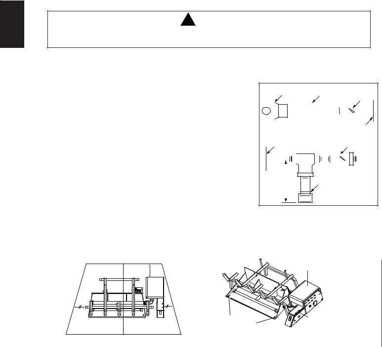
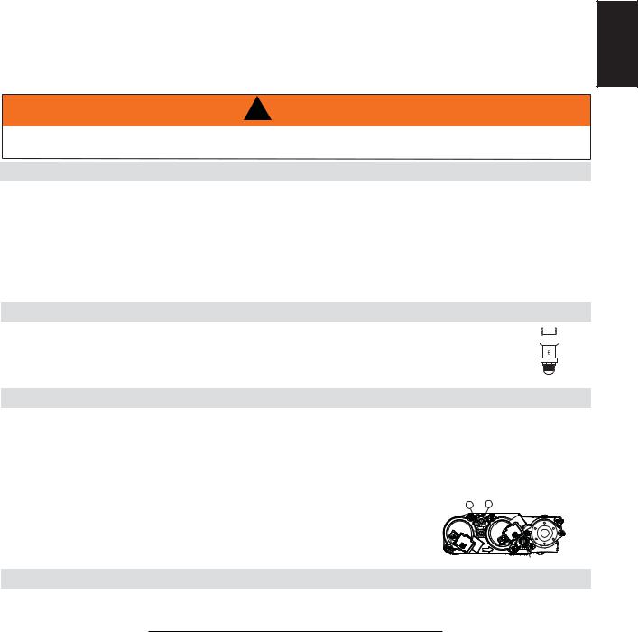
THE RATING PLATE IS CHAINED TO THE LEG OF THE VALVE CASE AND SHOULD BE UNDER THE VALVE HOUSING.
This rating plate illustration is for reference only. Refer to the rating plate on the appliance for accurate information.
NOTE: The rating plate must remain with the appliance at all times. It must not be removed.
W415-1101 / B / 07.29.13
3.0 INSTALLATION |
7 |
! WARNING |
|
THIS APPLIANCE MUST BE INSTALLED IN A SOLID-FUEL BURNING FIREPLACE WITH A WORKING |
EN |
FLUE AND CONSTRUCTED OF NON-COMBUSTIBLE MATERIAL. |
The appliance and gas logs function as a system. If the appliance is not drafting properly and spilling into the room (check with a match or a smoke stick), reposition the damper clamp until a positive draft is obtained by opening the damper. If negative pressure in home prevents having a positive draft, consult an air quality specialist.
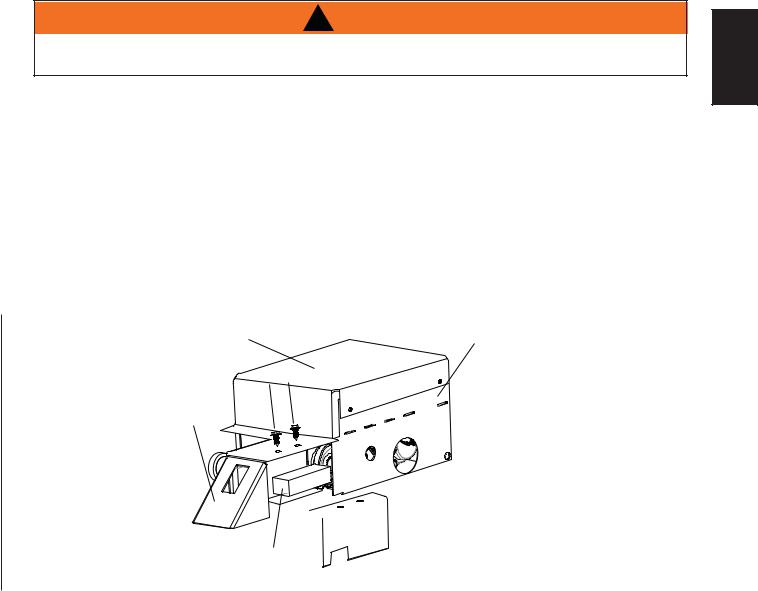
3.1BATTERY INSTALLATION
A.4 (1.5 V) AA size batteries are supplied and included in the manual bag.
B.Remove the 2 screws securing the support plate to gain access to the battery case, as shown below.
C.Install the four batteries into the battery case.
D.Insert the assembled battery case into the battery support. Ensure that the heat insulation gasket covers the top and left side of the battery case, as shown below
E.Reinstall the battery support plate.
SIDE VIEW
HEAT SHIELD |
VALVE |
|
HOUSING |
||
|
BATTERY
SUPPORT

 BATTERY
SUPPORT
PLATE
BATTERY
CASE
W415-1101 / B / 07.29.13
8
3.2GAS PIPING AND BURNER PLACEMENT
EN |
! WARNING |
DO NOT CONNECT EITHER THE WALL SWITCH, THERMOSTAT OR GAS VALVE TO ELECTRICITY
(110 VOLTS).
This appliance must be isolated from the gas supply piping system by closing the individual manual shut off valve during any pressure testing of the gas supply piping system at test pressure equal to or less than ½ psi (3.5 kPa)
A.Centre the burner pan and valve assembly in the fireplace opening, making sure the appliance is at least 1.5” (38.1mm) from the rear of the fireplace.
B. |
Secure the burner to the fireplace floor using the 2 screws |
|
|
|
Regulator |
|
|
|
|
|
|
|
|
|
|
|
Manual |
|||||||||||
|
|
|
Union |
|
|
|
Shut-Off |
|||||||||||||||||||||
|
provided. |
|
|
|
|
|
|
|
|
|
|
|
|
|
|
|
|
|
|
|
|
|
|
|
Valve |
|||
C. |
Install the gas line using piping ½” (12.7mm) in diameter or |
|
|
|
|
|
|
|
|
|
|
|
|
|
|
|
|
|
|
|
|
|
|
|
|
|
|
|
|
|
|
|
|
|
|
|
|
|
|
|
|
|
|
|
|
|
|
|
|
|
|
|
|
|
|
||
|
|
|
|
|
|
|
|
|
|
|
|
|
|
|
|
|
|
|
|
|
|
|
|
|
|
|
||
|
greater to provide the full volume of gas to the appliance. |
|
|
|
|
|
|
|
|
|
|
|
|
|
|
|
|
|
|
|
|
|
|
|
|
|
|
|
|
|
|
|
|
|
|
|
|
|
|
|
|
|
|
|
|
|
|
|
|
|
|
|
|
|
|
|
|
|
|
|
|
|
|
|
|
|
|
|
|
|
|
|
|
|
|
|
|
|
|
|
|
|
|
|
|
|
|
|
|
|
|
|
|
|
|
|
|
|
|
|
|
|
|
|
|
|
|
|
|
|
|
|
|
|
|
|
The installation of the gas line must be done to local and / or |
|
|
|
|
|
|
|
|
|
|
|
|
|
|
|
|
|
|
|
|
Appliance |
||||||
|
National codes. |
|
|
|
|
|
|
|
|
|
|
|
|
|
|
|
|
|
|
|
|
Wall |
||||||
D. |
When rigid pipe is used an ANSI approved manual shut off and |
|
|
|
|
|
|
|
|
|
|
|
|
|
|
|
|
|
|
|
|
|||||||
|
Appliance |
|
|
|
|
|
|
|
|
|
Shut-Off |
|||||||||||||||||
|
a union must be installed upstream within the appliance cavity. |
|
|
|
|
|
|
|
|
|
|
Key |
||||||||||||||||
|
|
|
|
|
|
|
|
|
|
|
|
|
|
|
|
|
|
|
|
|
||||||||
E. |
To ensure the appliance operates reliably install a sediment |
|
|
|
|
|
|
|
|
|
|
|
|
|
|
|
|
|
|
|
|
|
|
|
|
|
|
|
|
|
|
|
|
|
|
|
|
|
|
|
|
|
|
|
|
|
|
|
|
|
|
|
|
|
|
||
|
trap upstream of the appliance within the structures of the |
|
|
|
|
|
|
|
|
|
|
|
|
|
|
|
|
|
|
|
|
|
|
|
|
|
|
|
|
|
|
|
|
|
|
|
|
|
|
|
|
|
|
|
|
|
|
|
|
|
|
|
|
|
|
|
|
|
|
|
|
|
|
|
|
|
|
|
|
|
|
|
|
|
|
|
|
|
|
|
|
|
|
|
|
|
|
piping system. |
|
3" |
|
|
|
|
|
|
|
|
|
|
|
|
|
|
|
|
|
|
|
|
|
|
|
||
F. |
When using propane, a regulator must be used between |
|
(76.3mm) |
|
|
Sediment |
|
|
|
|
|
|
|
|
||||||||||||||
|
|
|
|
|
|
|
|
|
|
|
|
|
|
|
|
|
|
|
|
|
||||||||
|
the tank and the outside wall of the house to ensure the line |
|
|
|
|
|
|
|
|
|
|
|
|
|
|
|
Trap |
|
|
|
|
|
|
|
|
|||
|
pressure does not exceed 14”(355.6mm) w.c. inside the house. |
|
|
|
|
|
|
|
|
|
|
|
|
|
|
|
|
|
|
|
|
|
|
|
|
|
|
|
|
|
|
|
|
|
|
|
|
|
|
|
|
|
|
|
|
|
|
|
|
|
|
|
|
|
|
|
|
G.Check gas connections with a gas detection device to test for
leaks in the system. Soapy water mixture can also be used to check for leaks.
H.Once all the gas connections are tested for leaks, start the appliance. Follow the “OPERATING AND LIGHTING INSTRUCTIONS” section to ensure the appliance is working properly before finishing.
MIN. 1.5” |
(38.1mm) |
VALVE
HOUSING
SECURING |
BATTERY |
HOLES/SCREWS |
SUPPORT PLATE |
|
(BATTERY CASE |
|
SECURED INSIDE) |
W415-1101 / B / 07.29.13
9
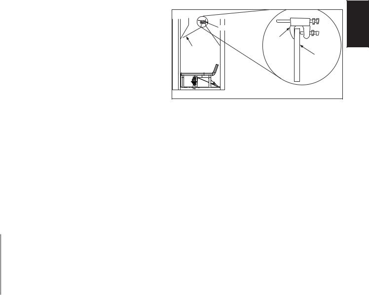
3.3DAMPER STOP INSTALLATION
The damper must be permanently locked in position to prevent full closure and to provide a minimum flue opening. Various methods for locking the damper may be used but may be restricted from region to region and it is important to know the specifics that apply to your area. For your convenience a damper stop is provided with the appliance and may be used where not prohibited by state or local codes.
Use the 3” (72.6mm) adjustable bolt to adjust the damper to the correct opening, based on the enclosed chart.
|
DAMPER STOP |
EN |
|
|
|
|
|
DAMPER |
DAMPER |
|
STOP |
|
|
|
|
|
DAMPER |
Should the damper stop not fit, or provide the required permanent opening from the Minimum Damper Opening table, have the damper cut to provide a minimum permanent opening or install an alternate stop.
Creosote, ashes and loose paint must be cleaned from the chimney flue and firebox by a qualified chimney cleaner, before installing in a solid fuel burning appliance. Any outside air ducts and/or ash dumps in the fireplace shall be permanently closed at time of appliance installation.
If the damper stop (supplied) is not applicable the damper may be fixed open by the following method:
•Drill a hole in either end of the damper.
•Using a bolt of sufficient length and adjustment, with 2 nuts, secure to damper through the hole.
•Adjust to correct opening.
*CHIMNEY HEIGHT |
|
MINIMUM DAMPER OPENING |
|
||
GL22 |
|
GL28 |
|
GL32 |
|
|
|
|
|||
6’ (1.8m) |
56.6” (1439mm) |
|
64” (6125.6mm) |
|
71.4” (1813.5mm) |
8’ (2.4m) |
52.4” (1331mm) |
|
59.7” (1516.8mm) |
|
66.9” (1699.2mm) |
10’ (3m) |
48.2” (1224.2mm) |
|
54.3” (1379.2mm) |
|
60.2” (1529mm) |
15’ (4.6m) |
43.2” (1097.2mm) |
|
48.8” (1239.5mm) |
|
54.1” (1374.1mm) |
20’ (6m) |
39.8” (1011mm) |
|
44.4”(1127.7mm) |
|
49.1 (1247.1mm) |
30’ (9.1m) |
35.9” (911.8mm) |
|
40.3” (1023.6mm) |
|
44.5 (1130.3mm) |
* Height is measured from the hearth to the top of the chimney.
W415-1101 / B / 07.29.13
10
4.0FINISHING
4.2SAND OR GLASS MEDIA PLACEMENT
EN |
A. |
Either sand for natural gas models (GL22N, GL28N, GL32N) or glass for propane models (GL22P, |
|
|
GL28P, GL32P), must be spread evenly over the burner pan with a gradual downward slope toward |
|
|
the front of the burner pan. |
B.Tear the ember material into small thin pieces and spread evenly on top of the media. Ember material will only glow when exposed to direct flame.
NOTE: DO NOT OVERFILL. DO NOT COVER THE PILOT WITH MEDIA OR EMBERS.
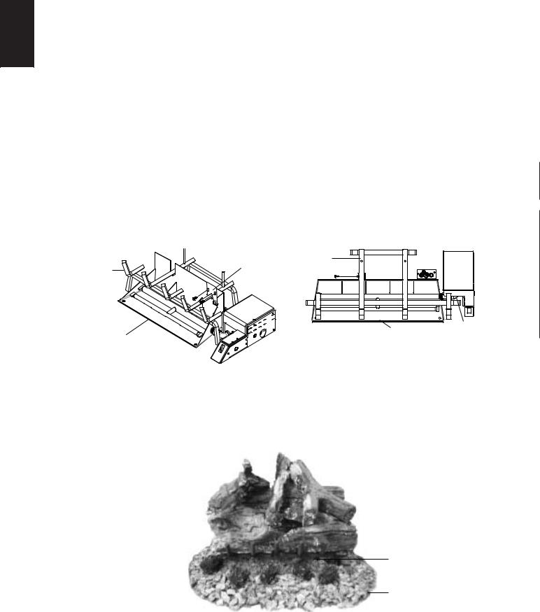
4.1GRATE INSTALLATION
A.For the best flame performance and least carbon, position the grate as far back as possible.
B.Secure the heat shield to the back of the burner pan with the 2 supplied screws (for GL22 model only), see Figure 1.
C.Secure the grate to the burner pan using one supplied screw, attached to the burner pan (for GL28/ GL32 models only), see Figure 2.
FIG. 1 |
FIG. 2 |
GL22 FRONT VIEW |
GL 28 / GL32 TOP VIEW |
HEAT SHIELD |
GRATE |
|
|
|
|
GRATE |
|
|
|
BURNER PAN |
AIR SHUTTER |
BURNER PAN |
(PROPANE |
|
|
MODELS ONLY) |
4.3CHARCOAL LUMPS/EMBERS
A.Sprinkle the charcoal embers around the front and sides of the burner pan, as indicated on the diagram below.
B.Place the charcoal lumps on top of the charcoal embers at the front of the media.
NOTE: Do not block air shutter opening with charcoal embers or lumps.
CHARCOAL |
|
GLOWING |
|
EMBERS |
|
LUMPS |
|
|
|
|
CHARCOAL
EMBERS
W415-1101 / B / 07.29.13
11
4.4LOG PLACEMENT
! WARNING |
EN |
FAILURE TO POSITION THE LOGS IN ACCORDANCE WITH THESE DIAGRAMS OR FAILURE TO USE ONLY LOGS SPECIFICALLY APPROVED WITH THIS APPLIANCE MAY RESULT IN PROPERTY DAMAGE OR PERSONAL INJURY.
LOGS MUST BE PLACED IN THEIR EXACT LOCATION IN THE APPLIANCE. DO NOT MODIFY THE PROPER LOG POSITIONS, SINCE APPLIANCE MAY NOT FUNCTION PROPERLY AND DELAYED IGNITION MAY OCCUR.
THE LOGS ARE FRAGILE AND SHOULD BE HANDLED WITH CARE.
76.1A
PhazerTM logs, exclusive to Napoleon Appliances, they provide a unique and realistic glowing effect that is different in every installation. Failure to follow these log placement instructions may increase sooting.
Log colours may vary. During the initial use of the appliance, the colours will become more uniform as colour pigments burn in during the heat activated curing process.
Positioning the logs improperly will increase flame impingement and carboning.
Blocked burner ports can cause an incorrect flame pattern, carbon deposits and delayed ignition. Use only certified PhazerTM logs available from your authorized dealer/distributor.
THE SUPPLIED LOG SETS ARE REVERSIBLE!
This feature allows you the option of displaying two different log styles in one log set.
PIN
4.4.1 GL22
PINS
#1 |
#2 |
#3 |
|
|
Place the rear log (#1) onto the 2 pins ensure the log is pushed flush against the burner support, to the rear of the unit, as shown.
#4
Place log (#2) onto the grate on the left side as shown.
#5
Place log (#3) onto the grate on the right side as shown. Place the pins into log (#1) as shown.
PIN
#6
Place log (#4) onto the left side pin as shown.
Place log (#5) onto the right side pin as shown.
Place log (#6) onto log (#1) and allow it to rest on log (#2).
W415-1101 / B / 07.29.13

12
4.4.2 GL28
EN
#1
Place log (#1) onto the two pins and ensure the log is pushed flush against the burner support, to the rear of the unit, as shown.
#4
Place log (#4) onto the pin.
#2
Place log (#2) directly onto the grate and ensure it is pulled to the front left side of the grate.
#5 PIN
Place log(#5) as shown and allow it rest on the top of the previously placed logs. Place one pin onto the right side of the largest log as shown.
PIN
#3
Place log (#3) onto the grate and ensure it is pulled to the front right side. Ensure the two logs are centered onto the grate. Insert one pin into the hole of the back log as shown.
#6
Place log (#6) onto the pin.
4.4.3 GL32
#1
Place the rear log (#1) onto the 2 pins on the grate as shown.
#4
Place log (#4) onto the pin.
#7
#2
Place log (#2) onto the grate as shown.
PIN
#5
Place log (#5) onto rear log and let it rest on log (#2). Place a second pin into log (#1) as shown.
Place log (#7) onto the pin as shown.
PIN
#3
Place log (#3) onto the grate as shown. Place one pin into centre of log (#1).
#6
Place log (#6) onto the pin as shown. Place the remaining pin into log (#1) as shown.
W415-1101 / B / 07.29.13

13
4.5MOBILE HOME INSTALLATION
This appliance is also certified to be installed as an OEM (Original Equipment Manufacturer) installation |
|
EN |
in a manufactured home (U.S. only) or mobile home and must be installed in accordance with the |
|
|
|
|
|
manufacturer’s instructions and the Manufactured Home Construction and Safety Standard, Title 24 CFR, |
|
|
Part 3280, in the United States or the Mobile Home Standard, CAN/CSA Z240 MH Series, in Canada. This |
|
|
appliance is only for use with the type(s) of gas indicated on the rating plate. |
|
|
|
|
|
This Mobile/Manufactured Home Listed appliance comes factory equipped with a means to secure the unit. Built in appliances are equipped with 1/4” (6.4mm) diameter holes located in the front left and right corners of the base. Use #10 hex head screws, inserted through the holes in the base to secure. For free standing products contact your local authorized dealer / distributor for the appropriate securing kit. For mobile home installations, the appliance must be fastened in place. It is recommended that the appliance be secured in all installations. Always turn off the pilot and the fuel supply at the source, prior to moving the mobile home. After moving the mobile home and prior to lighting the appliance, ensure that the logs are positioned correctly.
This appliance is certified to be installed in an aftermarket permanently located, manufactured (mobile) home, where not prohibited by local codes.
This appliance is only for use with the type of gas indicated on the rating plate. This appliance is not convertible for use with other gases, unless a certified kit is used.
A conversion kit is supplied with the mobile home appliance.
Conversion Kits
This appliance is field convertible between Natural Gas (NG) and Propane (LP). To convert from one gas to another consult your Authorized dealer/distributor.
29.1A
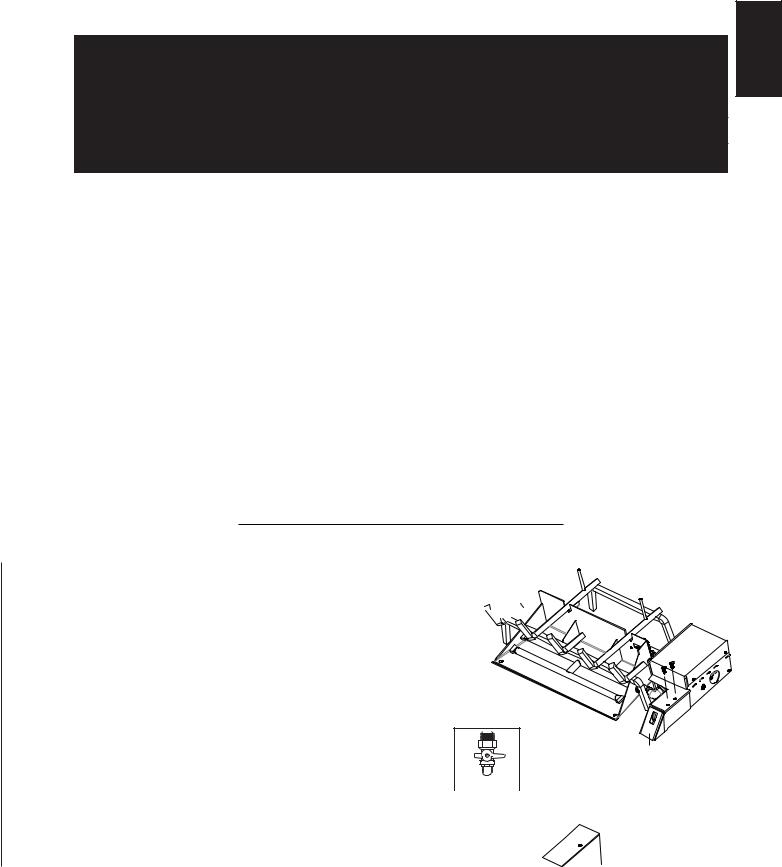
4.6 OPTIONAL REMOTE INSTALLATION (NOT SUPPLIED)
A. Place the remote receiver to the front right corner of the fireplace floor. B. Disconnect the wires connected to ON/OFF switch.
C. Connect those wires to the remote receiver.
D. Cover the remote receiver with the log provided. (Please refer to the remote kit leaflet for installation instructions.)
W415-1101 / B / 07.29.13
14
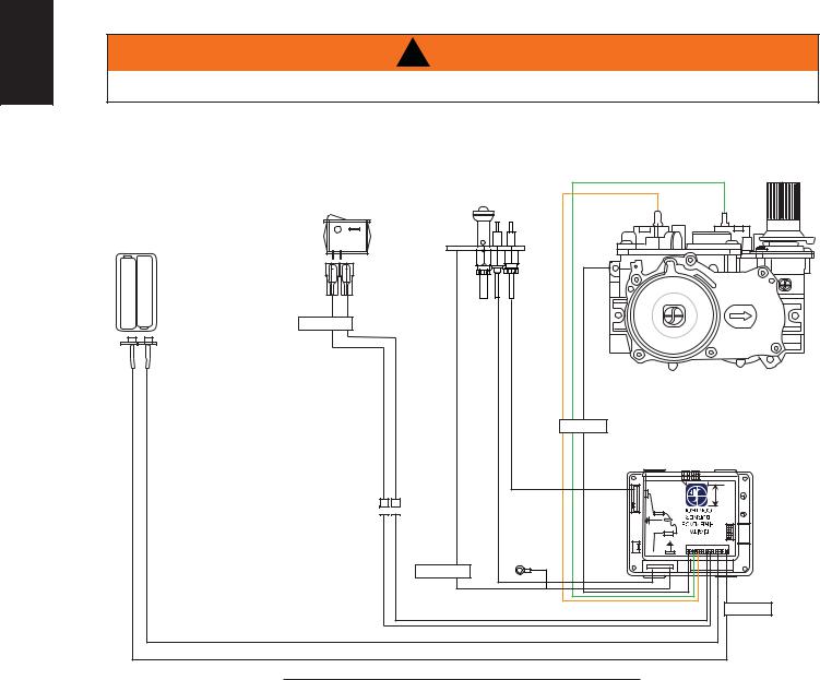
5.0WIRING DIAGRAM
EN |
! |
WARNING |
|
|
DO NOT WIRE 110 VOLTS TO THE VALVE OR WALL SWITCH.
This appliance comes equipped with a battery pack. Install four AA batteries into the holder and connect to the wire harness. Connect the battery holder to the wire harness before using the appliance. It must be connected to the 6 volt battery pack (supplied).
|
|
ON / OFF |
GREEN |
|
|
SWITCH |
ORANGE |
|
|
|
|
BATTERY |
|
|
|
HOLDER |
|
|
|
+ |
- |
|
|
- |
+ |
ON / OFF |
|
|
|
|
ELECTRONIC |
|
|
|
VALVE |
|
|
|
VALVE |
|
|
|
IPI BOARD |
|
|
|
GROUND |
|
|
|
EYELET |
|
|
|
GROUND |
|
|
|
DFC |
|
|
|
69.9 |
W415-1101 / B / 07.29.13
15
6.0 OPERATION
If the fireplace is equipped with decorative glass doors, they must be fully opened when operating this gas log
EN
set. Keep burner and control compartment clean.
6.1OPERATING AND LIGHTING INSTRUCTIONS
! WARNING
IF YOU DO NOT FOLLOW THESE INSTRUCTIONS EXACTLY, A FIRE OR EXPLOSION MAY RESULT
CAUSING PROPERTY DAMAGE, PERSONAL INJURY OR LOSS OF LIFE.
FOR YOUR SAFETY READ BEFORE LIGHTING:
A.Do not turn on if children or other at risk individuals are near the appliance.
B.Before operating smell all around the appliance area for gas and next to the floor because some gas is heavier than air and will settle on the floor.
C.Use only your hand to turn the gas control knob. Never use tools. If the knob will not turn by hand, do not try to repair it. Call a qualified service technician. Force or attempted repair may result in a fire or explosion.
D.Do not use this appliance if any part has been under water. Immediately call a qualified service technician to inspect the appliance and replace any part of the control system and any gas control which has been underwater.
WHAT TO DO IF YOU SMELL GAS:
•Turn off all gas to the appliance.
•Open windows.
•Do not try to light any appliance.
•Do not touch any electric switch; do not use any phone in your building.
• Immediately call your gas supplier from a 
 neighbour’s phone. Follow the gas
  supplier’s instructions.


• If you cannot reach your gas supplier, call the fire department.
LIGHTING INSTRUCTIONS:
1.Stop! Read the above safety information on this label.
2.Open the glass door if equipped.
3.Remove the batteries.
4.This appliance is equipped with an ignition device which automatically lights the pilot. Do not try to light the pilot by hand.
5.Turn manual shutoff valve clockwise to off. Located behind the appliance.
6.Wait five (5) minutes to clear out any gas. If you smell gas including near the floor, STOP! Follow
“B” in the above safety information on this label. If you don’t smell gas go to the next step.
7.Turn manual shutoff valve counter-clockwise to on.
8.Replace the batteries.
9.Turn switch on and listen for ignition sound.
A B
PILOT SCREW
TO TURN OFF GAS:
1.Remove the batteries.
2.Turn manual shutoff valve clockwise to off. Do not force.
47.20
W415-1101 / B / 07.29.13
16
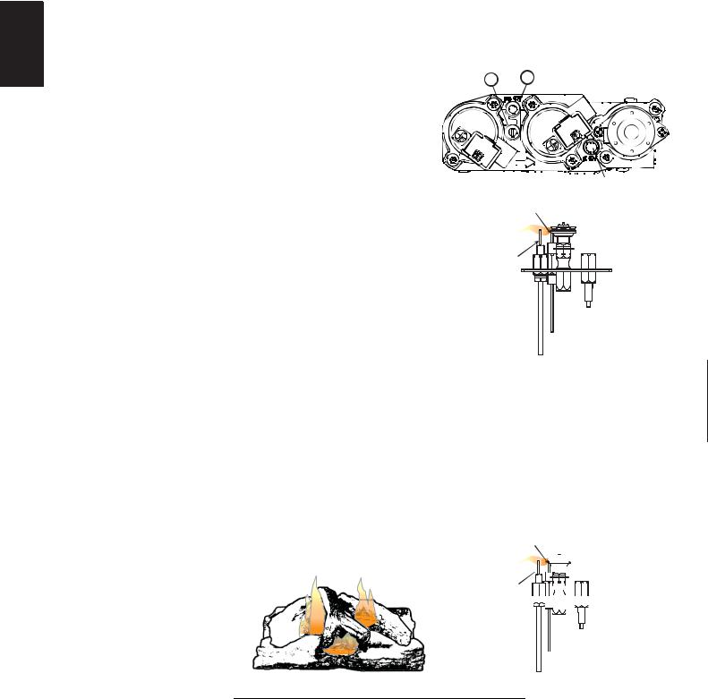
7.0ADJUSTMENTS
EN 7.1 PILOT BURNER ADJUSTMENT
Adjust the pilot screw to provide properly sized flame. Turn in a |
A |
B |
clockwise direction to reduce the gas flow. |
|
|
Check Pressure Readings:
Inlet pressure can be checked by turning screw (A) counterclockwise 2 or 3 turns and then placing pressure gauge tubing over the test point. Gauge should read as described on the chart below. Check that main burner is operating on “HI”.
Outlet pressure can be checked the same as above using |
|
|
|
|
|
|
|
PILOT SCREW |
||||||||
|
ELECTRODE PILOT |
|
|
|||||||||||||
screw (B). Gauge should read as described on the chart |
|
|
|
|
||||||||||||
below. Check that main burner is operating on “HI”. |
|
|
|
3/8” - 1/2” |
|
|
|
|
BURNER |
|
|
|||||
|
|
|
|
|
|
|
|
|
|
|
|
|
|
|
||
AFTER TAKING PRESSURE READINGS, BE SURE TO |
(9.5mm - 12.7mm) |
|
|
|
|
|
|
|
||||||||
|
|
|
|
|
|
|
|
|
|
|
||||||
TURN SCREWS CLOCKWISE FIRMLY TO RESEAL. DO |
|
FLAME |
|
|
|
|
|
|
||||||||
NOT OVERTORQUE. |
|
|
|
|
SENSOR |
|
|
|
|
|
|
|||||
Leak test with a soap and water solution. |
|
|
|
|
|
|
|
|
|
|
|
|
|
|
||
Prior to pilot adjustment, ensure that the pilot assembly |
|
|
|
|
|
|
|
|
FLAME MUST ENVELOP |
|||||||
has not been painted. If overspray or painting of the pilot |
|
|
|
|
|
|
|
|
||||||||
|
|
|
|
|
|
|
|
UPPER 3/8” (9.5mm) TO 1/2” |
||||||||
assembly has occurred remove the paint from the pilot |
|
|
|
|
|
|
|
|
(12.7mm) OF FLAME SENSOR |
|||||||
assembly, or replace. Fine emery |
|
|
|
|
|
|
|
|
|
|
|
|
|
|
|
|
cloth or sandpaper can be used to |
|
Pressure |
Natural Gas |
Natural Gas |
|
|
|
Propane |
|
Propane |
|
|||||
|
(inches) |
|
(millibars) |
|
|
|
(inches) |
|
(millibars) |
|
||||||
remove the paint from the pilot hood, |
|
|
|
|
|
|
||||||||||
|
|
|
7" |
|
17.4mb |
|
|
|
|
|
|
|
32.4mb |
|
||
electrode and flame sensor. |
|
Inlet |
|
|
|
13" |
|
|
||||||||
|
|
|
|
(MIN. 4.5") |
(MIN. 11.2mb) |
|
(MIN. 11") |
|
(MIN. 27.4mb) |
|
||||||
|
|
|
Outlet |
|
3.5" |
|
8.7mb |
|
|
|
10" |
|
24.9mb |
|
||
|
|
|
|
|
|
|
|
|
|
|
|
|
39.1C |
|
|
|
|
|
|
|
|
|
|
|
|
|
|
|
|
|
|||
7.2FLAME CHARACTERISTICS
It’s important to periodically perform a visual check of the pilot and burner flames. Compare them to the
illustration provided. If any flames appear abnormal call a service person. PILOT
ELECTRODE
BURNER
3/8” - 1/2”


 (9.5mm - 12.7mm)


FLAME 


 SENSOR


FLAME MUST ENVELOP
 UPPER 3/8” (9.5mm) TO 1/2”
(12.7mm) OF FLAME SENSO
54.1B
NOTE: FLAME WILL VARY DEPENDING ON THE POSITION OF THE LOGS AND THE GRATE.
W415-1101 / B / 07.29.13
17
8.0 MAINTENANCE
|
|
MAINTENANCE! |
EN |
WARNING |
|
TURN OFF THE GAS AND ELECTRICAL POWER BEFORE SERVICING THE APPLIANCE.
APPLIANCE MAY BE HOT, DO NOT SERVICE UNTIL APPLIANCE HAS COOLED.
DO NOT USE ABRASIVE CLEANERS.
DO NOT PAINT THE PILOT ASSEMBLY.
CAUTION: Label all wires prior to disconnection when servicing controls. Wiring errors can cause improper and dangerous operation. Verify proper operation after servicing. This appliance and its venting system should be inspected before use and at least annually by a qualified service person. The appliance area must be
kept clear and free of combustible materials, gasoline or other flammable vapours and liquids. The flow of combustion and ventilation air must not be obstructed.
1.In order to properly clean the burner and pilot assembly, remove the logs, rocks and/or glass to expose both assemblies.
2.Keep the control compartment, media, burner, air shutter opening and the area surrounding the appliance clean by vacuuming or brushing, at least once a year.
3.Check to see that all burner ports are burning. Clean out any of the ports which may not be burning or are not burning properly.
4.Check to see that the pilot flame is large enough to engulf the flame sensor and/or thermocouple / thermopile as well as reaches the burner.
5.Replace the cleaned logs, rocks or glass. Failure to properly position the media may cause carboning which can be distributed in the surrounding living area.
6.Check to see that the main burner ignites completely on all openings when turned on. A 5 to 10 second total light-up period is satisfactory. If ignition takes longer, consult your local authorized dealer / distributor.
7.Visually inspect the appliance for carbon build up. Using a small whisk or brush, brush off the carbon and vacuum up or sweep into garbage.
8.Check to see that the appliance is venting correctly. Ensure chimney system is safe and unobstructed.
40.19A
8.1BATTERY REPLACEMENT
A. Prior to replacing the battery, turn off the gas manual shut-off valve. B. Remove the four screws from the battery support plate, as shown. C. Remove the battery case from the battery support and remove 


the 4 (1.5 V) AA size batteries from the battery case and replace them with the new set of 4 (1.5 V) AA size batteries.
E. Place the battery case back into the battery support. F. Ensure when installing the battery case that the heat insullation
remains secured to the case.
G.Re-install the battery support plate and secure it using the 2 screws, as shown.
H. Turn the gas shut-off valve back to the on position.
|
|
O S |
|
WARNING: Turn the manual shut-off valve to the OFF |
|
|
|
MANUAL SHUT-OFF |
|||
position when changing the battery, as shown above. |
(SHOWN IN OFF POSITION) |
||
|
|
|
|
|
|
|
|
 BATTERY
SUPPORT
PLATE
BATTERY
SUPPORT
BATTERY 
 SUPPORT
  PLATE
PLATE
W415-1101 / B / 07.29.13
 Loading...