


NAIS RG1-12V, RG1-24V, RG1-3V, RG1T-12V, RG1T-24V Datasheet
...
HIGH FREQUENCY
RG RELAYS WITH 1C RG-RELAYS
AND 2C CONTACTS
25
.984 19
.748
10.4
.409
25 |
|
.984 |
23 |
|
.906 |
1 Form C
9.9
.390
2 Form C
mm inch
•Excellent high frequency characteristics Isolation: Min. 65dB (at 900 MHz) Insertion loss: Max. 1.0 (at 900 MHz)
•Wide selection
Characteristic impedance: 50 Ω type and 75 Ω type
Coil: Single side stable and latching type
•1 A 24 V DC switching capacity
•Sealed construction for automatic cleaning
•High sensitivity 350W (1 Form C) in small size
SPECIFICATIONS
Contact
Arrangement |
1 Form C, 2 Form C |
||||||
|
|
|
|
|
|
||
Contact material |
Gold-clad silver |
||||||
|
|
|
|
|
|
|
|
Initial contact resistance, max. |
100 mΩ |
||||||
(By voltage drop 6 V DC 1 A) |
|||||||
|
|
Max. switching power |
|
24 W |
|||
Rating |
|
Max. switching voltage |
24 V DC |
||||
(resistive) |
|
Max. switching current |
|
1 A |
|||
|
|
Nominal switching capacity |
1 A 24 V DC |
||||
High frequency characteristics |
50 Ω |
|
75 Ω |
||||
(at 900 MHz) |
|
||||||
|
|
|
|
Isolation |
Min. 65 dB |
|
Min. 65 dB |
|
|
|
|
Insertion loss |
Max. 1 dB |
|
Max. 1 dB |
|
|
|
|
V.S.W.R. |
Max. 1.2 |
|
Max. 2.0 |
Expected life |
|
Mechanical |
|
5×10⁶ |
|||
(min. operations) |
Electrical 1 A 24 V DC |
|
105 |
||||
Coil (polarized) (at 25°C, 68°F)
|
1 Form C |
2 Form C |
|
|
|
Single side stable |
350 mW |
400 mW |
1 coil latching |
175 mW |
200 mW |
2 coil latching |
350 mW |
400 mW |
Characteristics
Initial insulation resistance*1 |
Min. 100 MΩ at 500 V DC |
|
||||||
Initial |
|
Between open contacts |
1,000 Vrms |
|||||
|
Between contacts and coil |
2,000 Vrms |
||||||
breakdown |
||||||||
Between contacts and |
|
|
|
|||||
voltage* |
2 |
500 Vrms |
||||||
|
earth terminal |
|
||||||
|
|
|
|
|
|
|||
Operate time*3 (at nominal voltage) |
Approx. 10 ms |
|
||||||
Release time*3 (at nominal voltage)(without diode) |
Approx. 5 ms |
|
||||||
Set time*3 (at nominal voltage) |
Approx. 7 ms |
|||||||
Reset time*3 (at nominal voltage) |
Approx. 7 ms |
|
||||||
Temperature rise (at 20°C) |
Max. 55°C with nominal coil voltage |
|||||||
across coil and at nominal switching capacity |
|
|||||||
|
|
|
|
|
||||
Shock resistance |
|
Functional*4 |
Min. 196 m/s2 {20 G} |
|
||||
|
Destructive*5 |
Min. 980 m/s2 {100 G} |
|
|||||
|
|
|
|
|||||
|
|
|
|
Functional*6 |
10 to 55 Hz |
|||
|
|
|
|
at double amplitude of 2 mm |
|
|||
Vibration resistance |
|
|
||||||
|
Destructive |
10 to 55 Hz |
||||||
|
|
|
|
|||||
|
|
|
|
at double amplitude of 2 mm |
||||
|
|
|
|
|
||||
Conditions for operation, |
|
Ambient |
–50°C to 60°C |
|
||||
transport and storage |
|
temp. |
–58°F to 140°F |
|||||
(Not freezing and condens- |
|
|
|
|
|
|||
|
Humidity |
5 to 85%R.H. |
||||||
ing at low temperature) |
|
|||||||
Unit weight |
|
|
1 C type |
Approx. 8 g .282 oz |
|
|||
|
|
2 C type |
Approx. 10 g .353 oz |
|
||||
|
|
|
|
|||||
Remarks
* Specifications will vary with foreign standards certification ratings.
*1 Measurement at same location as “Intial breakdown voltage” section *2 Detection current: 10mA
*3 Excluding contact bounce time
*4 Half-wave pulse of sine wave: 11ms; detection time: 10 s *5 Half-wave pulse of sine wave: 6ms
*6 Detection time: 10 s
TYPICAL APPLICATIONS ORDERING INFORMATION |
|
|
||||
• Measuring instrument |
|
|
|
|
|
|
• Testing equipment |
Ex. RG |
1 |
T |
L |
5V |
|
• CATV converter |
||||||
|
|
|
|
|
||
• Audio visual equipment |
|
|
|
|
|
|
• TV game set |
Contact arrangement |
Characteristic impedance |
Operating function |
|||
|
||||||
|
|
|
|
|
Nil: Single side |
|
|
1:1 Form C |
Nil: 75 Ω |
|
Nil: stable |
||
|
2:2 Form C |
T: |
50 Ω |
|
L: 1 coil latching |
|
L2: 2 coil latching
Note: Standard packing; Carton: 50 pcs. Case 500 pcs.
Coil voltage
DC: 3, 5, 6, 9, 12, 24, 48 V
105

RG
TYPES ANE COIL DATA (at 20°C 68°F)
1 Form C
Single side stable
|
Nominal |
Pick-up |
Drop-out |
Coil |
Nominal |
Nominal |
Maximum |
|
Part No. |
voltage |
voltage, max. |
voltage, min. |
resistance, |
operating |
operating |
allowable |
|
voltage, V DC |
||||||||
|
V DC |
V DC |
V DC |
Ω (±10%) |
current, mA |
power, mW |
(40°C 104°F) |
|
RG1-3V |
3 |
2.4 |
0.3 |
25.7 |
117.3 |
350 |
3.6 |
|
RG1T-3V |
||||||||
|
|
|
|
|
|
|
||
RG1-5V |
5 |
4.0 |
0.5 |
71.4 |
70.3 |
350 |
6.0 |
|
RG1T-5V |
||||||||
|
|
|
|
|
|
|
||
RG1-6V |
6 |
4.8 |
0.6 |
103 |
58.3 |
350 |
7.2 |
|
RG1T-6V |
||||||||
|
|
|
|
|
|
|
||
RG1-9V |
9 |
7.2 |
0.9 |
231 |
38.9 |
350 |
10.8 |
|
RG1T-9V |
||||||||
|
|
|
|
|
|
|
||
RG1-12V |
12 |
9.6 |
1.2 |
411 |
29.2 |
350 |
14.4 |
|
RG1T-12V |
||||||||
|
|
|
|
|
|
|
||
RG1-24V |
24 |
19.2 |
2.4 |
1,646 |
14.6 |
350 |
28.8 |
|
RG1T-24V |
||||||||
|
|
|
|
|
|
|
||
RG1-48V |
48 |
38.4 |
4.8 |
6,583 |
7.3 |
350 |
57.6 |
|
RG1T-48V |
||||||||
|
|
|
|
|
|
|
1 coil latching
|
Nominal |
Set and reset |
Coil |
Nominal |
Nominal |
Maximum |
|
Part No. |
voltage |
voltage, |
resistance, |
operating |
operating |
allowable |
|
voltage, V DC |
|||||||
|
V DC |
V DC (max.) |
Ω (±10%) |
current, mA |
power, mW |
(40°C 104°F) |
|
RG1-L-3V |
3 |
2.4 |
51.4 |
58.3 |
175 |
3.6 |
|
RG1T-L-3V |
|||||||
|
|
|
|
|
|
||
RG1-L-5V |
5 |
4.0 |
142.8 |
35.8 |
175 |
6.0 |
|
RG1T-L-5V |
|||||||
|
|
|
|
|
|
||
RG1-L-6V |
6 |
4.8 |
206.8 |
29.2 |
175 |
7.2 |
|
RG1T-L-6V |
|||||||
|
|
|
|
|
|
||
RG1-L-9V |
9 |
7.2 |
462.8 |
19.4 |
175 |
10.8 |
|
RG1T-L-9V |
|||||||
|
|
|
|
|
|
||
RG1-L-12V |
12 |
9.6 |
822.8 |
14.6 |
175 |
14.4 |
|
RG1T-L-12V |
|||||||
|
|
|
|
|
|
||
RG1-L-24V |
24 |
19.2 |
3,292.8 |
7.3 |
175 |
28.8 |
|
RG1T-L-24V |
|||||||
|
|
|
|
|
|
||
RG1-L-48V |
48 |
38.4 |
13,166.8 |
3.6 |
175 |
57.6 |
|
RG1T-L-48V |
|||||||
|
|
|
|
|
|
2 coil latching
|
Nominal |
Set and reset |
Coil resistance, Ω (±10%) |
Nominal |
Nominal |
Maximum |
||
Part No. |
voltage |
voltage, |
|
|
operating |
operating |
allowable |
|
Coil 1 |
Coil 2 |
voltage, V DC |
||||||
|
V DC |
V DC (max.) |
current, mA |
power, mW |
(40°C 104°F) |
|||
RG1-L2-3V |
3 |
2.4 |
25.7 |
25.7 |
117.8 |
350 |
3.6 |
|
RG1T-L2-3V |
||||||||
|
|
|
|
|
|
|
||
RG1-L2-5V |
5 |
4.0 |
71.4 |
71.4 |
70.8 |
350 |
6.0 |
|
RG1T-L2-5V |
||||||||
|
|
|
|
|
|
|
||
RG1-L2-6V |
6 |
4.8 |
103 |
103 |
58.3 |
350 |
7.2 |
|
RG1T-L2-6V |
||||||||
|
|
|
|
|
|
|
||
RG1-L2-9V |
9 |
7.2 |
231 |
231 |
38.9 |
350 |
10.8 |
|
RG1T-L2-9V |
||||||||
|
|
|
|
|
|
|
||
RG1-L2-12V |
12 |
9.6 |
411 |
411 |
29.2 |
350 |
14.4 |
|
RG1T-L2-12V |
||||||||
|
|
|
|
|
|
|
||
RG1-L2-24V |
24 |
19.2 |
1,646 |
1,646 |
14.6 |
350 |
28.8 |
|
RG1T-L2-24V |
||||||||
|
|
|
|
|
|
|
||
RG1-L2-48V |
48 |
38.4 |
6,583 |
6,583 |
7.3 |
350 |
57.6 |
|
RG1T-L2-48V |
||||||||
|
|
|
|
|
|
|
||
2 Form C
Single side stable
|
Nominal |
Pick-up |
Drop-out |
Coil |
Nominal |
Nominal |
Maximum |
|
Part No. |
voltage |
voltage, max. |
voltage, min. |
resistance, |
operating |
operating |
allowable |
|
voltage, V DC |
||||||||
|
V DC |
V DC |
V DC |
Ω (±10%) |
current, mA |
power, mW |
(40°C 104°F) |
|
RG2-3V |
3 |
2.4 |
0.3 |
22.5 |
133.8 |
400 |
3.6 |
|
RG2T-3V |
||||||||
|
|
|
|
|
|
|
||
RG2-5V |
5 |
4.0 |
0.5 |
62.5 |
80.8 |
400 |
6.0 |
|
RG2T-5V |
||||||||
|
|
|
|
|
|
|
||
RG2-6V |
6 |
4.8 |
0.6 |
90 |
66.7 |
400 |
7.2 |
|
RG2T-6V |
||||||||
|
|
|
|
|
|
|
||
RG2-9V |
9 |
7.2 |
0.9 |
202.5 |
44.4 |
400 |
10.8 |
|
RG2T-9V |
||||||||
|
|
|
|
|
|
|
||
RG2-12V |
12 |
9.6 |
1.2 |
360 |
33.3 |
400 |
14.4 |
|
RG2T-12V |
||||||||
|
|
|
|
|
|
|
||
RG2-24V |
24 |
19.2 |
2.4 |
1,440 |
16.7 |
400 |
28.8 |
|
RG2T-24V |
||||||||
|
|
|
|
|
|
|
||
RG2-48V |
48 |
38.4 |
4.8 |
5,760 |
8.3 |
400 |
57.6 |
|
RG2T-48V |
||||||||
|
|
|
|
|
|
|
106
RG
1 coil latching
|
Nominal |
Set and reset |
Coil |
Nominal |
Nominal |
Maximum |
|
Part No. |
voltage |
voltage, |
resistance, |
operating |
operating |
allowable |
|
voltage, V DC |
|||||||
|
V DC |
V DC (max.) |
Ω (±10%) |
current, mA |
power, mW |
(40°C 104°F) |
|
RG2-L-3V |
3 |
2.4 |
45 |
66.7 |
200 |
3.6 |
|
RG2T-L-3V |
|||||||
|
|
|
|
|
|
||
RG2-L-5V |
5 |
4.0 |
125 |
40.8 |
200 |
6.0 |
|
RG2T-L-5V |
|||||||
|
|
|
|
|
|
||
RG2-L-6V |
6 |
4.8 |
180 |
33.3 |
200 |
7.2 |
|
RG2T-L-6V |
|||||||
|
|
|
|
|
|
||
RG2-L-9V |
9 |
7.2 |
405 |
22.2 |
200 |
10.8 |
|
RG2T-L-9V |
|||||||
|
|
|
|
|
|
||
RG2-L-12V |
12 |
9.6 |
720 |
16.7 |
200 |
14.4 |
|
RG2T-L-12V |
|||||||
|
|
|
|
|
|
||
RG2-L-24V |
24 |
19.2 |
2,880 |
8.3 |
200 |
28.8 |
|
RG2T-L-24V |
|||||||
|
|
|
|
|
|
||
RG2-L-48V |
48 |
38.4 |
11,520 |
4.2 |
200 |
57.6 |
|
RG2T-L-48V |
|||||||
|
|
|
|
|
|
2 coil latching
|
Nominal |
Set and reset |
Coil resistance, Ω (±10%) |
Nominal |
Nominal |
Maximum |
||
Part No. |
voltage |
voltage, |
|
|
operating |
operating |
allowable |
|
Coil 1 |
Coil 2 |
voltage, V DC |
||||||
|
V DC |
V DC (max.) |
current, mA |
power, mW |
(40°C 104°F) |
|||
RG2-L2-3V |
3 |
2.4 |
22.5 |
22.5 |
133.8 |
400 |
3.6 |
|
RG2T-L2-3V |
||||||||
|
|
|
|
|
|
|
||
RG2-L2-5V |
5 |
4.0 |
62.5 |
62.5 |
80.8 |
400 |
6.0 |
|
RG2T-L2-5V |
||||||||
|
|
|
|
|
|
|
||
RG2-L2-6V |
6 |
4.8 |
90 |
90 |
66.7 |
400 |
7.2 |
|
RG2T-L2-6V |
||||||||
|
|
|
|
|
|
|
||
RG2-L2-9V |
9 |
7.2 |
203 |
202.5 |
44.4 |
400 |
10.8 |
|
RG2T-L2-9V |
||||||||
|
|
|
|
|
|
|
||
RG2-L2-12V |
12 |
9.6 |
360 |
360 |
33.3 |
400 |
14.4 |
|
RG2T-L2-12V |
||||||||
|
|
|
|
|
|
|
||
RG2-L2-24V |
24 |
19.2 |
1,440 |
1,440 |
16.7 |
400 |
28.8 |
|
RG2T-L2-24V |
||||||||
|
|
|
|
|
|
|
||
RG2-L2-48V |
48 |
38.4 |
5,760 |
5,760 |
8.3 |
400 |
57.6 |
|
RG2T-L2-48V |
||||||||
|
|
|
|
|
|
|
||
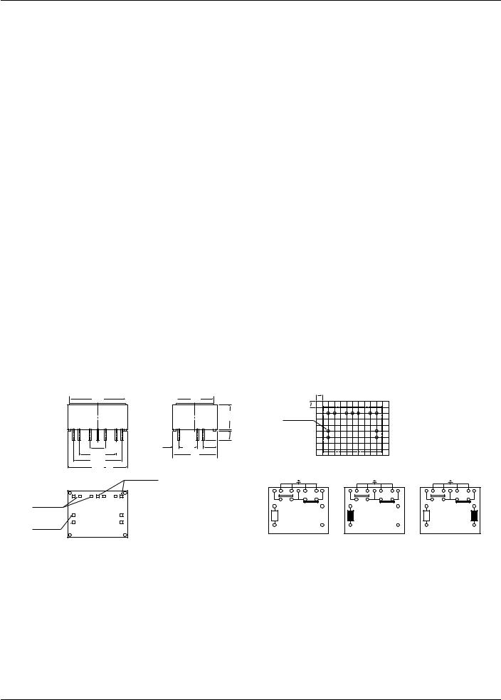
DIMENSIONS
mm inch
1 Form C type
21 |
|
15 |
.827 |
|
.591 |
|
|
|
|
|
9.9 |
|
|
|
|
|
.390 |
|
|
|
|
|
0.5 |
|
|
|
|
|
.020 |
|
|
2.61 |
|
|
3.7 |
|
5.08 |
7.62 |
2.54 |
.146 |
|
|
.103 |
|
|||
15.24 .200 |
|
.300 |
.100 |
|
|
|
19 |
|
|||
.600 |
|
|
.748 |
|
|
20.32 |
|
|
|
|
|
.800 |
25 |
3–0.5×0.4 |
|
|
|
|
.984 |
|
|
|
|
|
|
.020×.016 |
|
|
|
4–0.4×0.25
.016×.010
4–0.4×0.4
.016×.016 
Tolerance: ±0.3 ±.012
PC board pattern (Copper-side view)
|
2.54 |
2.54 |
.100 |
.100 |
|
11-1 DIA |
|
11-.039 DIA. |
|
|
Tolerance: ±0.1 ±.004 |
Schematic (Bottom view) |
|
|
|
|
|
|
|
|
|
|
|
|
|
|
|
|||||||
Deenergized condition |
Reset condition |
|
|
Reset condition |
|
|
||||||||||||||||
1 |
2 |
3 |
4 |
5 |
6 |
7 |
1 |
2 |
3 |
4 |
5 |
6 |
7 |
Setcoil |
1 |
2 |
3 |
4 |
5 |
6 |
7 |
Resetcoil |
+ |
16 |
|
|
|
18 |
|
– |
16 |
|
|
|
18 |
|
+ |
16 |
|
|
|
18 |
– |
||
– |
15 |
|
|
|
17 |
|
+ |
15 |
|
|
|
17 |
|
|
– |
15 |
|
|
|
17 |
+ |
|
Single side stable |
|
1 coil latching |
|
|
|
2 coil latching |
|
|
||||||||||||||
107
 Loading...