


NAIS K6EB-6V, K6EB-60V, K6EB-12V, K4EBP-12V-1, K4EB-6V-1 Datasheet
...
UL CSA VDE
Pending Pending Pending
UNIQUELY DESIGNED RELAY K-RELAYS
FEATURES
|
19 |
a |
.748 |
•100 times more reliable than similar designs
•Extra long life — Mechanical: more than 10 8 operations
Electrical (1 A 30 V): more than 106 operations
• Versatile range for all applications
30
1.181
|
|
|
a |
|
K2EB |
23.6 |
0.929 |
mm inch |
K4EB |
29.4 |
1.157 |
|
|
|
|
K6EB |
34.8 |
1.370 |
Sealed construction
Epoxy sealing resin
Plastic header |
Amber plastic cover
Gold-clad bifurcated contacts
Low and stable contact resistance Low level current switching possible
Gold-clad stationary |
Highly reliable |
contact |
bifurcated contacts |
Silver |
|
Silver |
Nickel silver |
|
Gold-clad |
contact arm |
|
movable contact |
||
|
SPECIFICATIONS
Contacts
Arrangement |
|
2, 4, 6 Form C |
|
|
|
|
|
|
Max. switching |
50 W, 100 VA |
|
|
power |
||
Rating |
|
||
Max. switching |
|
||
(resistive |
220 V AC DC |
||
voltage |
|||
load) |
|
||
|
|
||
Max. switching |
2A |
||
|
|||
|
current |
||
|
|
||
|
|
|
|
Expected |
Mechanical |
108 |
|
life (min. |
Electrical |
106 |
|
operations) |
(1 A 100 V AC) |
||
|
|||
|
|
|
|
Contact |
Movable contact |
Gold-clad silver |
|
material |
|
|
|
|
|
||
(Bifurcated |
Stationary contact |
Gold-clad silver |
|
contacts) |
|
|
|
Initial contact resistance, max. |
50 mΩ |
||
(By voltage drop 6 V DC 1 A) |
|||
|
|||
Capacitance |
Contact/Contact |
3 pF |
|
|
|
||
Contact/Ground |
5 pF |
||
|
|||
|
|
|
|
Characteristics (at 20°C 68°F, 50% R.H.)
Max. operating speed |
50 cps. |
||||
|
|
||||
Initial insulation resistance |
Min. 1,000 MΩ at 500 V DC |
||||
|
Between open contacts, |
750 Vrms |
|||
Initial |
contact sets |
||||
|
|||||
break- |
Between live parts and |
750 Vrms |
|||
down |
ground |
|
|||
|
|
||||
voltage |
Between contacts and |
750 Vrms |
|||
|
|||||
|
coil |
|
|||
|
|
|
|||
|
|
|
|
|
|
Operate time*1 |
|
Approx. 15 ms |
|||
(at nominal voltage) |
|
||||
|
|
||||
Release time*1 |
|
Approx. 5 ms |
|||
(at nominal voltage) |
|
||||
|
|
||||
Vibration resistance |
|
98 m/s2 {10 G}, 10 to 55 Hz at |
|||
|
double amplitude of 1.6 mm |
||||
|
|
|
|
||
Shock resistance |
|
98 m/s2 {10 G} |
|||
Conditions for |
|
Ambient |
2C, 4C: –40°C to +60°C –40°F to +140°F |
||
operation, trans- |
|
tempera- |
|||
|
6C: –40°C to +40°C –40°F to +104°F |
||||
port and storage |
|
ture*2 |
|||
|
|
||||
(Not freezing and |
|
|
|
||
condensing at low |
|
Humidity |
5 to 85% R.H. |
||
temperature) |
|
|
|
||
Ambient pressure |
|
101, 325 Pa ±20% |
|||
|
{1,013 mb ±20%} |
||||
|
|
|
|
||
Unit weight (approx.) |
|
K2EB: 23 g .81 oz, K4EB: 27 g .95 oz, |
|||
|
K6EB: 30 g 1.06 oz |
||||
|
|
|
|
||
*1 Excluding contact bounce time
*2 Total temperature (temperature rise in coil plus ambient temperature) should be kept less than max. 115°C 221°F
203
K
ORDERING INFORMATION
|
|
Ex. K |
|
2 |
|
|
EB |
|
P |
|
|
|
24V |
|
|
|
1 |
|
|
|
||||||
|
|
|
|
|
|
|
|
|
|
|
|
|
|
|
||||||||||||
|
|
|
|
|
|
|
|
|
|
|
|
|
|
|
|
|
|
|
|
|
|
|
|
|
|
|
|
|
|
|
|
|
|
|
|
|
|
|
|
|
|
|
|
|
|
|
|
|
|
|
|
|
|
|
|
|
|
|
|
|
|
|
|
|
|
|
|
|
|
|
|
|
|
|
|
|
|
|
|
|
Contact arrangement |
Type classigication |
|
|
Terminal |
|
|
|
Coil (DC) |
Sensitivity |
|||||||||||||||||
2: 2 Form C |
|
|
|
|
|
|
|
|
Nil: Plug-in, solder |
|
|
|
|
|
|
|
|
Nil: High sensitivity relays |
||||||||
EB: Amber sealed type |
|
|
|
|
|
|
terminal |
|
|
3 to 110 V |
||||||||||||||||
4: 4 Form C |
|
|
|
|
|
|
|
|
1: Ordinary sensitive |
|||||||||||||||||
|
|
|
|
|
P: PC board |
|
|
|||||||||||||||||||
6: 6 Form C |
|
|
|
|
|
|
|
|
|
|
|
|
|
|
|
|
relays |
|||||||||
|
|
|
|
|
|
|
|
|
terminal |
|
|
|
|
|
|
|
|
|||||||||
|
|
|
|
|
|
|
|
|
|
|
|
|
|
|
|
|
|
|
|
|
||||||
(Notes) 1. Other coil and contact specifications are available on request for orders of more than 1,000 pcs. (Notes) 1. Please state: Required coil resistance Gold clad/Gold clad contacts
(Notes) 2. For UL/CSA or VDE recognized types, and suffix UL/CSA or VDE. (Notes) 3. Standard packing Carton: 20 pcs. Case: 200 pcs.
TYPICAL APPLICATIONS
Typical applications include:
Systems and equipment requiring higher reliability, Severe environmental uses, Alarm devices, Office machines, Telecommunication equipment, Pollution control equipment
TYPES AND COIL DATA
|
Part No. |
|
|
Coil voltage (V) |
|
|
|
|
Inductance (H) |
||
|
|
|
|
|
|
|
|
Coil |
Nominal |
|
|
|
|
|
|
Pick-up |
Drop-out |
Max. |
|
Armature |
|||
|
|
|
Nominal |
allowable |
|
resistance* |
coil power |
|
|
||
Plug-in and Solder |
For PC board |
(DC) |
(max. at |
(min. at |
voltage, |
|
(Ω at 20°C) |
(mW) |
Closed |
Open |
|
|
|
|
20°C) |
20°C) |
|
||||||
|
|
|
|
(at 40°C) |
|
|
|
|
|
||
|
|
|
|
|
|
|
|
|
|
|
|
|
|
|
|
|
|
|
|
|
|
|
|
|
K2EB-3V-1 |
K2EBP-3V-1 |
3 |
1.8 |
0.27 |
6.7 |
|
28 |
320 |
0.52 |
0.26 |
|
|
|
|
|
|
|
|
|
|
|
|
|
K2EB-6V-1 |
K2EBP-6V-1 |
6 |
3.9 |
0.58 |
12.0 |
|
110 |
330 |
2.1 |
1.1 |
|
|
|
|
|
|
|
|
|
|
|
|
|
K2EB-12V-1 |
K2EBP-12V-1 |
12 |
8.0 |
1.2 |
30.0 |
|
530 |
270 |
11 |
5.6 |
|
|
|
|
|
|
|
|
|
|
|
|
2 Form C |
K2EB-24V-1 |
K2EBP-24V-1 |
24 |
16.5 |
2.5 |
47.0 |
|
1,700 |
340 |
35 |
18 |
|
|
|
|
|
|
|
|
|
|
|
|
|
K2EB-42V-1 |
K2EBP-42V-1 |
42 |
30.0 |
4.5 |
72.0 |
|
5,300 |
333 |
95 |
48 |
|
|
|
|
|
|
|
|
|
|
|
|
|
K2EB-48V-1 |
K2EBP-48V-1 |
48 |
39.0 |
5.9 |
100.0 |
|
7,600 |
300 |
120 |
62 |
|
|
|
|
|
|
|
|
|
|
|
|
|
K2EB-110V-1 |
K2EBP-110V-1 |
110 |
60.0 |
9.0 |
180.0 |
|
16,000 |
760 |
270 |
138 |
|
|
|
|
|
|
|
|
|
|
|
|
|
K4EB-3V-1 |
K4EBP-3V-1 |
3 |
2.3 |
0.35 |
5.0 |
|
18 |
500 |
0.36 |
0.18 |
|
|
|
|
|
|
|
|
|
|
|
|
|
K4EB-6V-1 |
K4EBP-6V-1 |
6 |
4.2 |
0.63 |
9.0 |
|
58 |
620 |
1.0 |
0.5 |
|
|
|
|
|
|
|
|
|
|
|
|
|
K4EB-12V-1 |
K4EBP-12V-1 |
12 |
8.7 |
1.3 |
18.5 |
|
250 |
580 |
5.2 |
2.6 |
4 Form C |
|
|
|
|
|
|
|
|
|
|
|
K4EB-24V-1 |
K4EBP-24V-1 |
24 |
18.0 |
2.7 |
35.0 |
|
890 |
650 |
15 |
7.5 |
|
|
|
|
|
|
|
|
|
|
|
|
|
|
K4EB-28V-1 |
K4EBP-28V-1 |
28 |
19.0 |
2.85 |
33.0 |
|
1,100 |
713 |
20 |
11 |
|
|
|
|
|
|
|
|
|
|
|
|
|
K4EB-48V-1 |
K4EBP-48V-1 |
48 |
36.0 |
5.4 |
64.0 |
|
3,200 |
720 |
54 |
28 |
|
|
|
|
|
|
|
|
|
|
|
|
|
K4EB-110V-1 |
K4EBP-110V-1 |
110 |
85.0 |
12.8 |
160.0 |
|
16,000 |
760 |
270 |
138 |
|
|
|
|
|
|
|
|
|
|
|
|
|
K6EB-6V |
|
6 |
4.2 |
0.63 |
6.6 |
|
28 |
1,286 |
0.52 |
0.26 |
|
|
|
|
|
|
|
|
|
|
|
|
|
K6EB-12V |
|
12 |
8.4 |
1.26 |
13.2 |
|
110 |
1,309 |
2.1 |
1.1 |
|
|
|
|
|
|
|
|
|
|
|
|
6 Form C |
K6EB-24V |
|
24 |
16.8 |
2.52 |
26.4 |
|
440 |
1,309 |
8.3 |
4.2 |
|
|
|
|
|
|
|
|
|
|
|
|
K6EB-48V |
|
48 |
33.6 |
5.04 |
52.8 |
|
1,700 |
1,355 |
35 |
18 |
|
|
|
|
|||||||||
|
|
|
|
|
|
|
|
|
|
|
|
|
K6EB-60V |
|
60 |
42.0 |
6.3 |
66.0 |
|
2,800 |
1,286 |
44 |
23 |
|
|
|
|
|
|
|
|
|
|
|
|
|
K6EB-110V |
|
110 |
77.0 |
11.55 |
121.0 |
|
10,000 |
1,210 |
164 |
84 |
|
|
|
|
|
|
|
|
|
|
|
|
|
|
|
|
|
|
|
* Less than 1,000 Ω: ±10% |
More than 1,000 Ω: ±15% |
|||
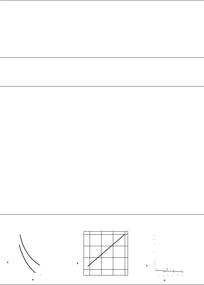
REFERENCE DATA
1. Life curve
|
|
|
|
|
|
30 V DC |
|
|
|
|
|
|
|
||||||
2,000 |
|
|
|
|
|
|
|
|
|
|
|
|
|
|
|
|
|
||
|
|
|
|
|
|
|
|
|
|
|
|
|
|
|
|
|
|||
1,000 |
|
|
|
|
|
|
|
|
|
|
|
|
|
|
|
|
|
||
|
|
|
|
|
|
|
|
|
|
|
|
|
|
|
|
|
|||
4 |
|
|
|
|
|
|
|
|
|
|
|
|
|
|
|
|
|
|
|
|
|
|
|
|
|
|
|
|
|
|
|
|
|
|
|
|
|
|
|
|
|
|
|
|
|
|
|
|
|
|
|
|
|
|
|
|
|
|
|
|
|
|
|
|
|
|
|
|
|
|
|
|
|
|
|
|
|
|
|
×10 |
|
|
|
|
|
|
|
|
|
|
|
|
|
|
|
|
|
|
|
|
|
|
|
|
|
|
|
|
|
|
|
|
|
|
|
|
|
||
operationsofNo. |
100 |
|
|
|
|
|
|
|
|
|
|
|
|
|
|
|
|
|
|
|
|
|
|
|
|
|
|
|
|
|
|
|
|
|
|
|
|||
|
|
|
|
|
|
|
|
|
|
|
|
|
|
|
|
|
|
|
|
|
|
10 |
|
|
|
|
|
|
|
|
|
|
|
|
|
|
|
|
|
|
|
|
|
|
|
|
|
|
|
|
|
|
|
|
|
|
|
|
|
|
|
|
|
|
|
|
|
|
|
|
|
|
|
|
|
|
|
|
|
|
|
|
|
|
|
|
|
|
|
|
|
|
|
|
|
|
|
|
|
|
|
|
|
|
|
|
|
|
|
|
|
|
|
|
|
|
|
|
|
|
|
|
|
|
|
|
|
|
|
|
|
|
|
|
|
|
|
|
|
|
|
|
|
|
|
|
|
|
|
|
|
|
|
|
|
|
|
|
|
|
|
|
|
|
|
|
|
|
|
|
|
|
|
|
|
|
|
|
|
|
|
|
|
|
|
|
|
|
|
|
|
L |
|
|
|
|
|
|
|
|
|
|
|
|
|
|
|
|
|
|
|
|
R |
|
= 0 |
|
|
||
|
|
|
|
|
|
|
|
|
|
|
|
|
|
|
|||||
|
|
|
|
|
|
|
|
|
|
|
|
|
|
|
|
|
|
||
|
|
|
|
|
|
|
|
|
L |
|
|
|
|
|
|
|
|
|
|
|
|
|
|
|
|
|
|
|
|
|
= 7 ms |
|
|
|
|||||
|
|
|
|
|
|
|
|
|
|
|
|
|
|
|
|
||||
|
|
|
|
|
|
|
|
|
R |
|
|
|
|
||||||
|
|
|
|
|
|
|
|
|
|
|
|
|
|
|
|
|
|||
|
|
|
|
|
|
|
|
|
|
|
|
|
|
|
|
|
|
|
|
|
|
|
1 |
2 |
3 |
4 |
|
|
5 |
|
|
|
|||||||
|
|
|
|
|
|
|
|
Current, A |
|||||||||||
|
|
|
|
|
|
|
|
||||||||||||
2. Coil temperature rise (resistance method)
|
|
80 |
°C |
|
|
rise, |
|
|
temperature |
60 |
|
|
|
|
Coil |
40 |
|
|
||
|
|
20 |
|
|
|
0.5 |
1.0 |
1.5 |
2.0 |
 Operating power, W
3. H2S gas test (1,000 ppm)
|
|
400 |
|
|
|
|
|
|
|
|
|
|
|
mΩ |
300 |
|
|
|
|
|
|
|
|
|
|
|
|
200 |
|
|
|
|
|
|
|
|
|
|
|
||
resistance, |
|
|
|
|
|
|
|
|
|
|
|
||
100 |
|
|
|
|
|
|
|
|
|
|
|
||
Contact |
50 |
|
|
|
|
|
|
|
|
|
|
|
|
|
|
|
|
|
|
|
|
|
|
|
|
|
|
|
|
40 |
|
|
|
|
|
Sealed KE relay (Au/Ag contact) |
|||||
|
|
30 |
|
|
|
|
|
||||||
|
|
|
|
|
|
|
|||||||
|
|
|
|
|
|
|
|
|
|
|
|
|
|
|
|
20 |
|
|
|
|
|
|
|
|
|
|
|
|
|
|
|
|
|
|
|
|
|
|
|
|
|
|
|
|
|
|
|
|
|
|
|
|
|
|
|
|
|
0 |
8 |
16 |
24 |
32 |
40 |
48 |
|
||||
|
|
|
|
|
|
|
|
Exposure time, hrs. |
|||||
|
|
|
|
|
|
|
|
||||||
204
 Loading...