


Nady Systems UWS100, UWS100LTHM20U, UWS100HT, UWS100LTHM1, UWS100GT User Manual
...O w n e r ’ s M a n u a l
UWS-100
100-Channel Select UHF Wireless System

Contents |
|
Introduction.............................................................................................................................. |
2 |
Using this Manual.................................................................................................................... |
2 |
System Features...................................................................................................................... |
3 |
Quick User Controls Guide...................................................................................................... |
4 |
System Operation |
|
UWS-100 Receiver............................................................................................................... |
8 |
UHT-100 Handheld Microphone Transmitter...................................................................... |
10 |
UBT-100 Bodypack Microphone/Instrument Transmitter.................................................... |
11 |
Cautions and Troubleshooting................................................................................................. |
14 |
Miscellaneous Tips.................................................................................................................. |
15 |
Specifications.......................................................................................................................... |
16 |
Frequency Plan....................................................................................................................... |
17 |
Optional Accessories.............................................................................................................. |
17 |
Service Information................................................................................................................. |
17 |
Warranty.................................................................................................................................. |
18 |
Introduction
Thank you for choosing the Nady UWS-100 wireless system, and congratulations on your choice. The UWS-100 has the best performance and price value in professional UHF wireless, offering clear-channel, frequency-agile operation on the UHF band for interference-free performance in any application or locale. The UWS-100 delivers 100 user-selectable channels, frequency synthesized in 00-99 channels in the US frequency band 667MHz-697MHz. The built-in Autoscan feature offers a quick and convenient way
to select an open channel for single system use or to set up many wireless systems at the same location for simultaneous multichannel operation. The UWS-100 features proprietary companding and low-noise circuitry for an industry-best 120dB dynamic range, and the clearest, most natural sound available in wireless today
Using This Manual
This booklet provides instructions for the operation of the UWS-100 and includes a description of features, a quick user controls guide, a step-by-step guide to operations for each unit, system specifications, a troubleshooting guide, miscellaneous tips, and servicing information.
System Features
UWS-100 System
•Unsurpassed state-of-the-art PLL UHF performance with 120dB dynamic range and operation, up to 500 ft. (line-of-sight)
•DigiTRU Diversity™ for maximum range and dropout protection
•100 UHF frequencies per band. Clear channels user selectable manually or with Autoscan for quick, convenient set up, with selected channel stored in memory for subsequent use.
•ASC™ (Auto-Sync Channels) download feature sends selected Channel information to transmitter via IR sender for easy frequency synchronization
•Sophisticated IF filtering for optimal simultaneous operation of multiple systems in the same location
•Front panel touch control buttons for ease of channel selection and ASC™ operation
•Dual front panel permanently attached swivel antennas
•Full front panel LED indicators including A/B diversity, Channel selected, ASC™ transfer status, and bi-color (green/red) AF level
•Back panel On/Off switch, balanced XLR fixed Mic Level and adjustable unbalanced ¼” jack audio Line Level outputs; squelch (RF mute) adjust; DC input jack; volume control for ease of operation
•Externally powered with included DC adapter (15 VDC 400 mA)
•Rugged all-metal receiver for long-term durability
•Choice of transmitters: UHT-100 handheld mic or UBT-100 bodypack—lavalier (LT), Headmic™ (HM), or instrument (GT)
•Optional RMT-1KUD available for rackmounting single or dual UWS-100 receivers
•UHT-100 Handheld Mic Transmitter
•Off/On/Mute power switch allows
convenient audio muting with the transmitter on
•RF power HI/LO and TX power lock On/Off switches
•LCD display indicates Power/Battery Level status and Channel selected
•Convenient, economical operation with two AA alkaline or NiMH batteries
•Features the Nady DM-10D unidirectional neodymium dynamic cartridge for optimal true sound, maximum feedback rejection and minimal handling noise
•Sleek housing with internal antenna for durable long life and optimum aesthetics
•Rubber-feel finish for sure grip
UBT-100 Bodypack Transmitter
•Off/On/Mute power switch allows convenient audio muting with the transmitter on
•LCD display indicates Power/Battery Level status and Group/Channel selected
•Convenient, economical operation with two AA alkaline or NiMH batteries
•Easily accessible input level adjustment (HM/LT)
•Compact housing, durable removable antenna and unique locking 3.5mm mini plug connector for mic or instrument cable
2 |
3 |
Quick User Controls Guide
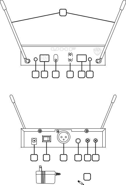
UWS-100 Receiver: Front View
1
-100
PLL WIRELESS SYSTEM |
|
|
|
Diversity™ |
|
A |
|
C™ SYSTEM |
|
|
|
|
AF |
RF |
|
|
|
|
|
A |
|
B |
B |
|
|
|
|
SELECT CHA NNEL |
|
IR |
ASC |
2 3 4 5 6 7
UWS-100 Receiver: Back View
15VDC IN |
POWER |
|
|
|
LINE OUT |
VOLUME MUTE LEVEL |
|||
400mA |
UNBALANCED |
|||
|
|
|||
|
MIC OUT |
– |
+ MIN MAX |
|
|
|
|
||
|
BALA NCED |
|
|
|
8 9 10 11 12 13
 14
14
1.DUAL ANTENNAS Permanently mounted. Rotate to 45° as shown for optimal reception
2.SELECT BUTTON Press once quickly to start the Auto Scan function to search for an interference-free channel. Press and hold for ~2 seconds to manually select one of 100 channels
3.CHANNEL DISPLAY LED indicator displays the selected channel from 00-99 in numerical format
4.AF LED INDICATOR Bi-color LED (green/orange) displays received audio level (orange indicates maximum allowable audio level)
5.RF A/B LED INDICATORS Indicate diversity A or B antenna reception when transmitter is on
6.IR WINDOW Transmits LED Infrared signal for linking the receiver to the transmitter for frequency downloads, with blinking IR LED status indicator
7.ASC™ SYNC BUTTON Starts the IR link download of the receiver’s selected channel to the transmitter. Position the transmitter IR receptor window 6-12” away from the receiver IR window, press the ASC button once and wait one second for the receiver to respond. The red LED inside the IR window will flash twice within two seconds. If the IR data download is successful, the transmitter LCD display’s backlight will light and the receiver’s RF A/B LED will also light, indicating reception of the receiver signal from the transmitter
8.DC INPUT JACK For connecting external AC/DC adapter to power receiver (DC15VDC/400mA)
9.POWER ROCKER SWITCH Press right side to turn On or press left side to turn Off receiver. The Channel Display (3) is lit when the unit is on
10.BALANCED MIC OUT XLR JACK Audio output at fixed MIC level
11.UNBALANCED LINE OUT ¼” JACK Line level audio output, adjustable with Volume control
12.VOLUME CONTROL Selects desired output volume level for the Unbalanced Line Out
13.MUTE LEVEL (RF SQUELCH) Controls the mute level for the receiver. Turn clockwise for maximum range or turn counterclockwise, if needed, to minimize noises from outside RF interference upon muting
14.DC POWER SUPPLY ADAPTER DC15VDC/400mA
4 |
5 |

Quick User Controls Guide
UHT-100 Handheld Transmitter: Front and Back
15 |
16 |
17 |
18 |
16A

 16C
16C
16B 


19 |
20 |
|
NADY UHT-100 |
|
|
|
21 |
22 |
23
15. MIC BALL Windscreen
16A. LCD DISPLAY: CHANNEL Indicates channel
(00 99)
16B. LCD DISPLAY: BATTERY Indicates battery status from one (weakest) to five (strongest) bars. Flashing “BATT” indicates low battery
16C. LCD DISPLAY: TX LOCK KEY Indicates Power On/Off switch is locked (see #20)
17.IR RECEPTOR SENSOR/WINDOW Infrared LED sensor for linking the transmitter microphone to the receiver during IR frequency downloads
18.OFF/STBY/ON Slide power switch to ON or OFF to turn mic on/off, or to STBY to turn on power with audio muted
19.BATTERY COMPARTMENT Holds two AA alkaline or NiMH batteries— observe correct polarity
20.TRANSMITTER lock switch Slide the switch to ON to lock the TX, or OFF to unlock the TX. (IR channel programming still functions normally)
21.RF power HI/LO Slide the switch to HI for more RF output, or LOW for less RF output— consumes less battery power in this setting and also better for simultaneous multichannel operation applications
22.INTERNAL ANTENNA For best operating range, do not handle this antenna during use
23.BATTERY COVER Slide open battery slot to insert batteries
Quick User Controls Guide
UB-100 Bodypack Transmitter
24
25 26
LOBAT |
|
|
ON |
OF |
F |
STDB |
Y |
|
UBT-100
28 |
IR |
 ASC™ SYSTEM
40
41
42
27A
27
27B
29
30
31
24.ANTENNA Removable antenna—should be attached during operation
25.OFF/STDBY/ON SWITCH Slide power switch to ON or OFF to turn on/off. Set to STDBY to turn power on with audio muted
26.INPUT JACK Locking 3.5mm mini-jack for connecting audio input cord from lapel mic (LT), Headmic™ (LT/HM), or instrument (GT) cable
27A. LCD DISPLAY: CHANNEL Indicates channel
(00 99)
27B. LCD DISPLAY: BATTERY Indicates battery status from one (weakest) to five (strongest) bars and flashing “BATT” for low battery
28. BELT CLIP On back of unit
29.IR RECEPTOR SENSOR Infrared LED sensor for linking the transmitter to the receiver during IR frequency download
30.LATCHING BATTERY COMPARTMENT DOOR
Slide open to insert batteries
31.BATTERY COMPARTMENT Holds two AA alkaline or NiMH batteries
37.INPUT VOLUME LEVEL (On back of unit) Adjusts input (LT/HM) audio level for optimal sound
40.INSTRUMENT CORD GT cable—connects Instrument’s audio output to TX input jack
41.HEADMIC™ Headworn microphone — connects to transmitter input jack
42.LAVALIER MIC Lavalier (lapel) microphone— connects to transmitter input jack
6 |
7 |
 Loading...