


 ® CI9060/9120
Six Channel Amplifier
Twelve Channel Amplifier
Owner’s Manual
Manuel d’Installation
Bedienungsanleitung
Manual del Usuario
Manuale delle Istruzioni
Manual do Proprietário
Bruksanvisning
Gebruikershandleiding
NEDERLANDS SVENSKA PORTUGUÊS ITALIANO ESPAÑOL DEUTSCH FRANÇAIS ENGLISH

2
ENGLISH |
FRANÇAIS |
DEUTSCH |
NEDERLANDS |
ESPAÑOL |
ITALIANO |
PORTUGUÊS |
SVENSKA |

Introduction
TABLE OF CONTENTS
I Introduction . . . . . . . . . . . . . . . . . . . . . . . . . . . . . . . . . . . . . . . . . . . . . . . . . . . . . . . . . . . . . . .3-5
Note to Installation personnel . . . . . . . . . . . . . . . . . . . . . . . . . . . . . . . . . . . . . . . . . . . . . . . . . . . 3
Safety Instructions . . . . . . . . . . . . . . . . . . . . . . . . . . . . . . . . . . . . . . . . . . . . . . . . . . . . . . . . . . . 4
II Operation . . . . . . . . . . . . . . . . . . . . . . . . . . . . . . . . . . . . . . . . . . . . . . . . . . . . . . . . . . . . . . .6-10
NAD ATO Logic . . . . . . . . . . . . . . . . . . . . . . . . . . . . . . . . . . . . . . . . . . . . . . . . . . . . . . . . . . . . . 6
NAD OMC . . . . . . . . . . . . . . . . . . . . . . . . . . . . . . . . . . . . . . . . . . . . . . . . . . . . . . . . . . . . . . . . . 7
NAD Protection Circuitry . . . . . . . . . . . . . . . . . . . . . . . . . . . . . . . . . . . . . . . . . . . . . . . . . . . . . . . 7
Rear panel connections. . . . . . . . . . . . . . . . . . . . . . . . . . . . . . . . . . . . . . . . . . . . . . . . . . . . . . . . 8
Front panel connections . . . . . . . . . . . . . . . . . . . . . . . . . . . . . . . . . . . . . . . . . . . . . . . . . . . . . . 10
III Installation . . . . . . . . . . . . . . . . . . . . . . . . . . . . . . . . . . . . . . . . . . . . . . . . . . . . . . . . . . . . .11-16
Rack Mount . . . . . . . . . . . . . . . . . . . . . . . . . . . . . . . . . . . . . . . . . . . . . . . . . . . . . . . . . . . . . . . 11
Shelf Mount . . . . . . . . . . . . . . . . . . . . . . . . . . . . . . . . . . . . . . . . . . . . . . . . . . . . . . . . . . . . . . . 11
Speaker Hook-up . . . . . . . . . . . . . . . . . . . . . . . . . . . . . . . . . . . . . . . . . . . . . . . . . . . . . . . . . . . 12
Client Configuration (Flex-Pad) . . . . . . . . . . . . . . . . . . . . . . . . . . . . . . . . . . . . . . . . . . . . . . . . . 14
Client Configuration (input/channel destination) . . . . . . . . . . . . . . . . . . . . . . . . . . . . . . . . . . . . 15
IV Troubleshooting . . . . . . . . . . . . . . . . . . . . . . . . . . . . . . . . . . . . . . . . . . . . . . . . . . . . . . . . . . .17
V Specifications . . . . . . . . . . . . . . . . . . . . . . . . . . . . . . . . . . . . . . . . . . . . . . . . . . . . . . . . . . . . . .18
VI Fuse Replacement Chart . . . . . . . . . . . . . . . . . . . . . . . . . . . . . . . . . . . . . . . . . . . . . . . . . . . . .19
ATTENTION: INSTALLATION PERSONNEL
The mounting hardware was specifically engineered for the NAD CI-series amplifier. We recommend that you do not substitute the mounting hardware.
Due to the high-power capability of the NAD CI-series amplifier, the power supplies are heavy and may require more than one installation person to rack-mount the amplifier.
NOTE
The amplifier’s weight must always rest on its bottom feet when placed on to a surface. Never put the amplifier down on its rear panel, with its front panel facing up. Doing so risks damage to the input/output connectors.
The amplifier generates a moderate amount of heat, requiring internal ventilation. Do not permit the air inlet and outlet grilles on the top, bottom, side, and back cover to be obstructed by papers or other materials.
NOTE
To prevent a fire or shock hazard, do not permit liquid or moisture to enter the amplifier. If liquid is accidentally spilled on it, immediately shut off the power and unplug the AC Mains cable from the wall outlet.
Do not open the amplifier or attempt to modify or repair it yourself. Refer all servicing to a qualified technician.
Specifications or design subject to change without notice.
All specifications are those in effect at time of printing.
NAD®, OMC™, ATO Logic™, and Flex-Pad™ are trademarks of NAD Electronics International, a division of Lenbrook Industries Limited.
©2000 NAD Electronics International, a division of Lenbrook Industries Limited
SVENSKA PORTUGUÊS ITALIANO ESPAÑOL NEDERLANDS DEUTSCH FRANÇAIS ENGLISH
3
SVENSKA PORTUGUÊS ITALIANO ESPAÑOL NEDERLANDS DEUTSCH FRANÇAIS ENGLISH
Introduction
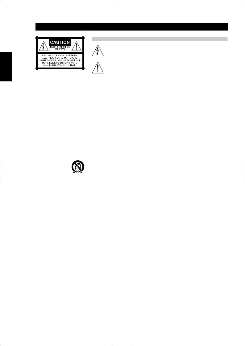
EXPLANATION OF GRAPHICAL SYMBOLS
The lightning flash with arrowhead symbol, within an equilateral triangle, is intended to alert the user to the presence of uninsulated “dangerous voltage” within the product’s enclosure that may be of sufficient magnitude to constitute a risk of electric shock to persons.
The exclamation point within an equilateral triangle is intended to alert the user to the presence of important operating and maintenance (servicing) instructions in the literature accompanying the appliance.
PRECAUTIONS
Read the Operating Instructions carefully and completely before operating the unit. Be sure to keep the Operating Instructions for future reference. All warnings and cautions in the Operating Instructions and on the unit should be strictly followed, as well as the safety suggestions below.
INSTALLATION
1Water and Moisture - Do not use this unit near water, such as near a bathtub, washbowl, swimming pool, or the like.
2Heat - Do not use this unit near sources of heat, including heating vents, stoves, or other appliances that generate heat. It also should not be placed in temperatures less than 5°C (41°F) or greater then 35°C (95°F).
3Mounting surface - Place the unit on a flat, even surface.
4Ventilation - The unit should be situated with adequate space around it so that proper ventilation is assured. allow 10 cm (4 in.) clearance from the rear and the top of the unit, and 5 cm (2 in.) from each side. - Do not place on a bed, rug, or similar surface that may block the ventilation openings. - Do not install the unit in a bookcase cabinet, or airtight rack where ventilation may be impeded.
5Objects and liquid entry - Take care that objects or liquids do not get inside the unit through the ventilation openings.
6Carts and stands - When placed or mounted on a stand or cart, the unit should be moved with care.
Quick stops, excessive force, and uneven surfaces may cause the unit and cart to overturn or fall.
7 Wall or ceiling mounting - The unit should not be mounted on a wall or ceiling, unless specified in the Operating Instructions.
WARNING! TO REDUCE THE RISK OF FIRE OR ELECTRONIC SHOCK, DO NOT EXPOSE
THIS APPLIANCE TO RAIN OR MOISTURE
This product is manufactured to comply with the radio interference requirements of EEC DIRECTIVE 89/68/EEC and 73/23/EEC
4
Introduction
ELECTRIC POWER
1Power Sources - Connect this unit only to power sources specified in the Operating Instructions, and as marked on the unit.
2Polarization - As a safety feature, some units are equipped with polarized AC power plugs which can only be inserted one way into a power outlet. If it is difficult or impossible to insert the AC power plug into an outlet, turn the plug over and try again. If it still does not easily insert into the outlet, please call a qualified service technician to service or replace the outlet. To avoid defeating the safety feature of the polarized plug, do not force it into a power outlet.
3AC power cord - When disconnecting the AC power cord, pull it out by the AC power plug. Do not pull the cord itself.
•Never handle the AC power plug with wet hands, as this could result in fire or shock.
•Power cords should be routed to avoid being severely bent, pinched, or walked upon. Pay particular attention to the cord from the unit to the power socket.
•Avoid overloading AC outlets and extension cords beyond their capacity, as this could result in fire or shock.
4Extension cord - To help prevent electric shock, do not use a polarized AC power plug with an extension cord, receptacle, or other outlet unless the polarized plug can be completely inserted to prevent exposure of the blades of the plug.
5When not in use - Unplug the AC power cord from the AC outlet if the unit will not be used for several months or more. When the cord is plugged in, a small amount of current continues to flow to the unit, even when the power is turned off.
CAUTION
Modifications or adjustments to this product, which are not expressly approved by the manufacturer, may void the user’s right or authority to operate this product.
DAMAGE REQUIRING SERVICE
Have the unit serviced by a qualified service technician if
•The AC power plug has been damaged.
•Foreign objects or liquid have gotten inside the unit.
•The unit has been exposed to rain or water - The unit does not seem to operate normally.
•The unit exhibits a marked change in performance.
•The unit has been dropped, or the cabinet has been damaged
DO NOT ATTEMPT TO SERVICE THE UNIT YOURSELF
OWNER’S RECORD
For your convenience, record the model number and serial number (you will find them on the rear of your set) in the space provided below. Please refer to them when you contact your dealer in case of difficulty.
Model No. :
Serial No. :
SVENSKA PORTUGUÊS ITALIANO ESPAÑOL NEDERLANDS DEUTSCH FRANÇAIS ENGLISH
5

Operation
SVENSKA PORTUGUÊS ITALIANO ESPAÑOL NEDERLANDS DEUTSCH FRANÇAIS ENGLISH
NAD ATO LOGIC
The CI-series amplifier may be turned on in any one of three discrete ways for complete system flexibility: From the front-panel switch, the 12V-TRIGGER circuit, or by a “SLEEP/WAKE” signal-sensing circuit. The ON/OFF power control is managed by the Automated Turn-On logic or ATO Logic circuit that requires the amplifier to be switched back to standby in the same manner by which it was activated. In other words, if the amplifier is switched on via a 12V-control signal, it cannot be switched to standby via the front-panel switch, it must wait for removal of the 12V-control signal. In practice, you probably would use only one of the methods once the NAD CI-series amplifier is installed.
ATO LOGIC CHART
SWITCH |
Amber LED over |
Green |
Green |
Green |
|
front power switch |
SWITCH LED |
12V-TRIGGER LED |
SENSE LED |
||
|
|||||
VACATION switch set to VACATION |
OFF |
OFF |
OFF |
OFF |
|
|
|
|
|
|
|
VACATION switch set to ON |
ON |
OFF |
OFF |
OFF |
|
|
|
|
|
|
|
Press front power switch with |
OFF |
ON |
OFF |
OFF |
|
VACATION switch set to ON |
|||||
|
|
|
|
||
|
|
|
|
|
|
Press front power switch with |
ON |
OFF |
OFF |
OFF |
|
VACATION switch set to ON |
|||||
|
|
|
|
||
|
|
|
|
|
|
12V TRIGGER |
Amber LED over |
Green |
Green |
Green |
|
front power switch |
SWITCH LED |
12V-TRIGGER LED |
SENSE LED |
||
|
|||||
VACATION switch set to VACATION |
OFF |
OFF |
OFF |
OFF |
|
|
|
|
|
|
|
VACATION switch set to ON |
ON |
OFF |
OFF |
OFF |
|
|
|
|
|
|
|
12 V INPUT TRIGGER = 0V with |
ON |
OFF |
OFF |
OFF |
|
VACATION switch set to ON |
|||||
|
|
|
|
||
|
|
|
|
|
|
12V INPUT TRIGGER = 12V with |
OFF |
OFF |
ON |
OFF |
|
VACATION switch set to ON |
|||||
|
|
|
|
||
|
|
|
|
|
|
SLEEP/WAKE |
Amber LED over |
Green |
Green |
Green |
|
front power switch |
SWITCH LED |
12V-TRIGGER LED |
SENSE LED |
||
|
|||||
VACATION switch set to VACATION |
OFF |
OFF |
OFF |
OFF |
|
|
|
|
|
|
|
VACATION switch set to ON |
ON |
OFF |
OFF |
OFF |
|
|
|
|
|
|
|
SLEEP/WAKE SENSE DEFEAT switch |
|
|
|
|
|
set to SENSE DEFEAT with VACATION |
ON |
OFF |
OFF |
OFF |
|
switch set to ON |
|
|
|
|
|
SLEEP/WAKE SENSE DEFEAT switch |
|
|
|
|
|
set to SLEEP/WAKE and any source |
OFF |
OFF |
OFF |
ON |
|
input greater than 20mV with |
|||||
|
|
|
|
||
VACATION switch set to ON |
|
|
|
|
|
|
|
|
|
|
6

Operation
NAD OMC
NAD’s proprietary Output Management Circuit (OMC) ensures that the full power is available at any reasonable load impedance. The OMC controls individual amplifier channels by managing the input level, in case of deliberately excessive input signal, and/or output level, in case of speaker or speaker cable fault. This not only protects the amplifier, but it also prevents loads attached to the amplifier from heating up excessively, an important factor when the reliability of an installed system is a consideration. When the OMC detects a potential fault situation and begins to limit current flow, an amber-coloured LED illuminates on the front panel to alert the installer/owner of a problem in the system. When the OMC is activated, the amplifier will continue to play without distortion, but the power level will be reduced to the amplifier channel that has the problem. If the fault condition persists and the impedance becomes too low the affected channels will initiate the NAD Protection Circuitry (see NAD Protection Circuitry below).
NAD PROTECTION CIRCUITRY
Every design decision, both electronic and mechanical, was made with absolute reliability of the amplifier as the primary goal. An auto-resetting protection circuit is also part of the CI-series amplifiers’ design. The fast acting protection circuit jumps into action if the amplifier overheats or encounters a short circuit condition. A red front-panel LED indicates that the Protection circuit has been activated. Only the amplifiers being affected by a short circuit condition will be in the protection mode; all other channels will continue to play normally. When the condition is normalized the affected channels reset. In the unlikely event of amplifier failure, the CI-series amplifier is designed to be easily field serviceable with all amplifying circuitry mounted on plug-in modules.
SVENSKA PORTUGUÊS ITALIANO ESPAÑOL NEDERLANDS DEUTSCH FRANÇAIS ENGLISH
7
SVENSKA PORTUGUÊS ITALIANO ESPAÑOL NEDERLANDS DEUTSCH FRANÇAIS ENGLISH
Operation
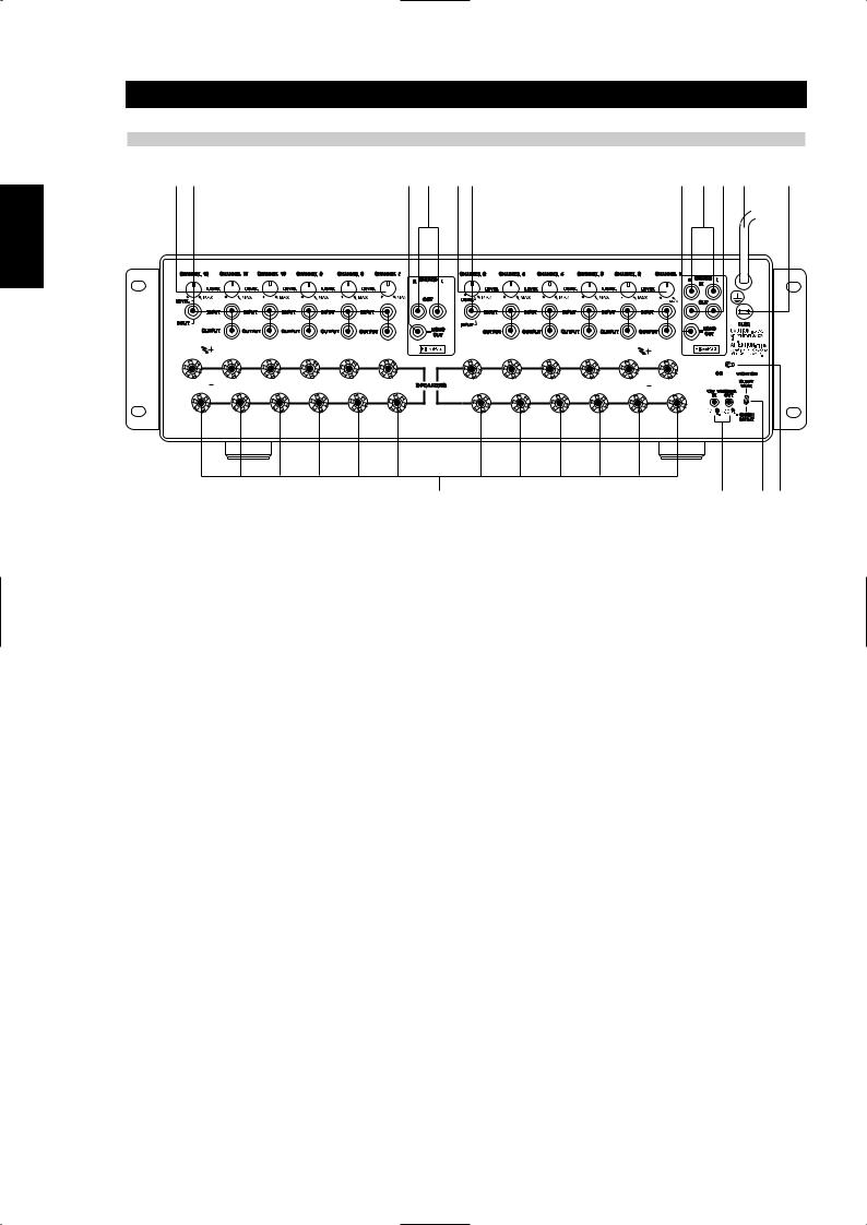
REAR-PANEL CONTROLS AND CONNECTIONS
1 |
2 |
3 |
4 |
1 |
2 |
3 |
5 |
4 |
10 |
11 |
9 |
8 |
7 |
6 |
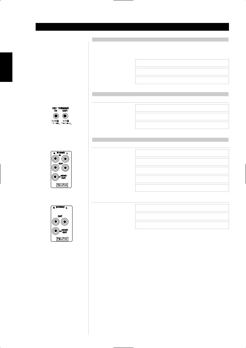
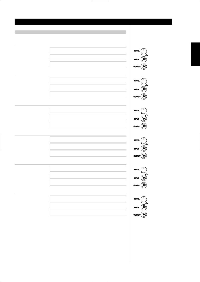
1There is one CHANNEL trimmer per amplifier channel. Each trimmer will attenuate each input from a minimum to MAX setting (approx - 13 dB to 0.0 dB). We have designed the adjustment range sufficient to match the speaker sensitivity both from room-to-room and per speaker for multi-speaker installations. The design of this trimmer is for sensitivity matching only, not a volume control. It is highly unlikely one would adjust the trimmers once the installation was complete, thus for this reason we have placed the trimmers at the back of the amplifier.
2Each amplifier CHANNEL INPUT OUTPUT is a direct pass-through connection, thus the source impedance of each channel input is exactly the impedance of the output. The special design of the NAD RCA cables that accompany the NAD CI-series amplifier allow for up to 6 channels to be fed from one channel of the Flex-Pad STEREO and MONO OUT, without degradation in sound quality. For example, one can jumper from Flex-Pad OUT Right to CHANNEL 1 INPUT, then from CHANNEL 1 OUTPUT to CHANNEL 2 INPUT, from CHANNEL 2 OUTPUT to CHANNEL 3 INPUT, and so on up to 6 channels of inputs. The NAD CI-series RCA jumper cables are specially designed low-capacitance high-performance cables. We do not recommend that you use any other RCA jumper cables than the NAD RCA jumper cables supplied with the NAD CIseries amplifier, to do so may cause significant loss in music fidelity or possible other problems.
3The Flex-Pad MONO OUT is a sum of the stereo right and left inputs with an output impedance of 75 ohms. We do not recommend driving more than 6 amplifier inputs with this MONO OUT source.
4The Flex-Pad STEREO right and left OUT is a stereo buffer with an output impedance of 75 Ohms per output, capable of driving up to 6 NAD CI-series amplifier inputs per output. We do not recommend you drive more than 6 amplifier inputs per Flex-Pad output.
5The Flex-Pad STEREO right and left IN is a high-impedance input specifically designed for connection to preamplifier or home-theatre processor outputs. We strongly recommend that these inputs not be connected to equipment that does not have a volume control!
6The VACATION switch is the master on/off control for the amplifier. When the switch is in the on state the amplifier is in standby as shown by the amber LED above the power switch on the front panel. If the amplifier will not be used for an extended period of time, switch the VACATION switch to the VACATION position.
7The SLEEP/WAKE, SENSE/DEFEAT switch logic controls the standby/on-state of the amplifier via the presences or absence of audio signal at the Flex-Pad or amplifier channel inputs. The
SLEEP/WAKE, SENSE/DEFEAT switch must be in the SLEEP/WAKE position in order to use this logic. When the SLEEP/WAKE, SENSE/DEFEAT switch is in the SENSE/DEFEAT position, this logic control is deactivated.
When the switch is in the SLEEP/WAKE position, the NAD CI-series amplifier will instantaneously turn on from a standby state, sensing any input signal from any channel as seen by a lit green SENSE LED on the front panel of the amplifier (approximately above 20mV RMS input). If all of the audio signals are absent for approximately 5 minutes, the amplifier will switch automatically to standby condition, with the green SENSE LED off, and the amber LED over the front panel switch lit.
When the switch is in the SENSE/DEFEAT position, the amplifier will not turn on even if an input signal is present on any channel or Flex-Pad input.
8
8The 12V TRIGGER IN and OUT connectors are 3.5mm monotype miniature phone jacks, with the centre pin of each serving respectively as a 12V signal sensor and 12V signal driver. We recommend that you use a good quality cable with shield when attaching the 3.5mm monotype plugs so as to prevent false triggering of the amplifier due to electro-magnetic interference from nearby electronic equipment.
The 12V-IN TRIGGER allows you to have an external 12V signal turn on the NAD CI-series amplifier from standby. This 12V signal must be a continuous 12V signal in order to keep the amplifier in the on state. Once you remove the 12V signal the amplifier will return to standby. The 12V-OUT TRIGGER allows you to control other products with a 12V sensor, by the NAD CI-series amplifier. The 12V-OUT TRIGGER is constantly present when the NAD CI-series amplifier is in the on state, and absent when in standby or VACATION state.
NOTES
•Check the specifications of the trigger input terminal on the other components to ensure these are compatible with the NAD CI-series amplifiers.
•All 12V-TRIGGER inputs and outputs on other NAD components with a 12V-TRIGGER feature are fully compatible with the NAD CI–series amplifier’s IN/OUT 12V-TRIGGER.
•Before making any connections to any 12V-TRIGGER input or output, make sure all components are disconnected from the AC mains.
•If in doubt over the connections, installation and/or operation of the IN/OUT 12V-TRIGGER connections consult your NAD dealer or sales representative.
•Failure to observe the above may result in damage to the NAD CIseries amplifier and/or any ancillary components attached to it.
9There is one set of speaker terminals per amplifier channel. They are marked “+” and “-” to indicate their polarity.
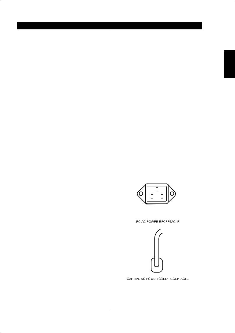
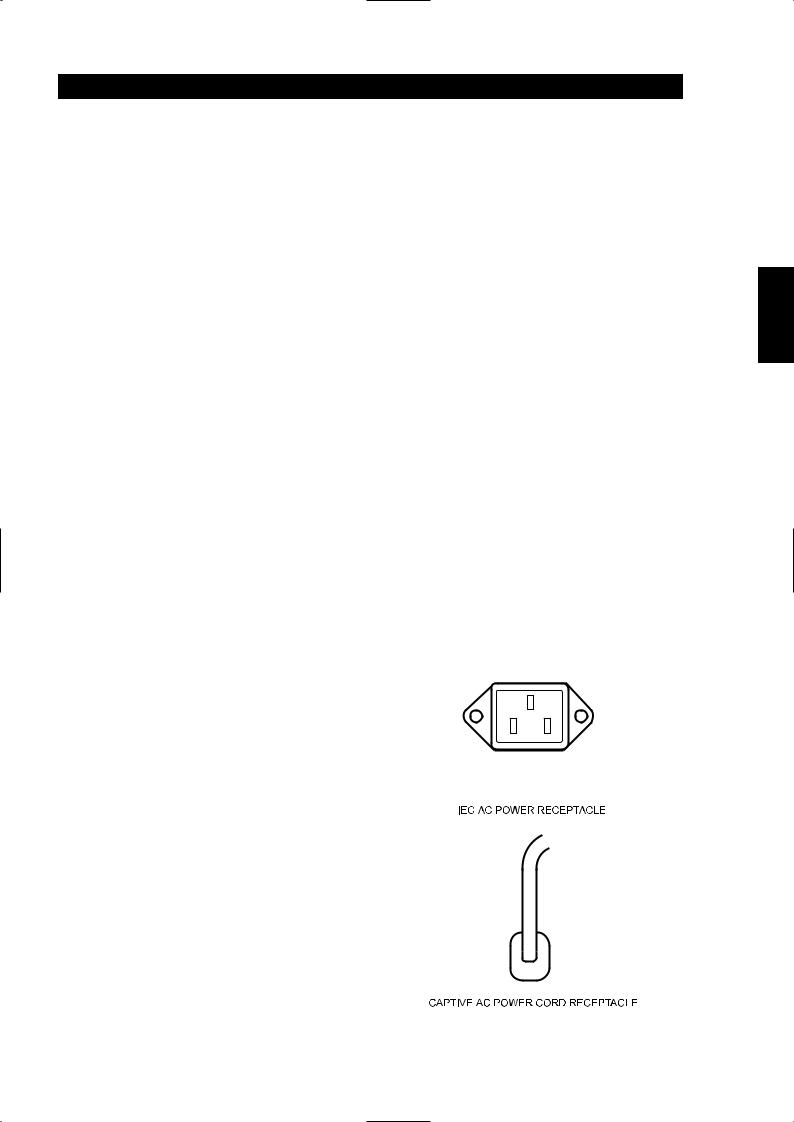
10There are two discrete-types of AC-power cords. Refer to figures below for the type that relates to your NAD CI-series amplifier:
Before connecting the AC-power cord to a live wall socket insure that all inputs/outputs are connected first. Always disconnect the ACpower cord plug from the live wall socket first, before disconnecting any cable from the CI-series amplifier. If you must use an extension cord, select a heavy-duty cord of the type used for large electrical appliances, such as an air conditioner AC-extension cord (16 AWG). We strongly recommend that you not connect the amplifier’s mains cable to the accessory AC outlets on a preamplifier. Such convenience outlets are not designed to supply the high-power levels that the NAD CI-series amplifier requires.
11There is a fuse holder nearby or next to the AC-line cord. In the unlikely event a fuse may need to be replaced, unplug the line cord form the wall. Then remove all connections from the amplifier. Only replace the fuse with the same type, size, and specification. Refer to “SPECIFICATIONS, NAD Models CI 9060 and CI 9120” at the back of this instruction manual for the correct number, type and size of the replacement fuse.
CAUTION
Failure to replace the fuse with the correct number, brand name, and type listed in the “FUSE REPLACEMENT - PLEASE NOTE CAREFULLY” chart, found in the back of this instruction manual under section “Fuse Replacement Chart” will eventually lead to either another blown fuse or amplifier damage.
Operation
SVENSKA PORTUGUÊS ITALIANO ESPAÑOL NEDERLANDS DEUTSCH FRANÇAIS ENGLISH
9
SVENSKA PORTUGUÊS ITALIANO ESPAÑOL NEDERLANDS DEUTSCH FRANÇAIS ENGLISH
Operation
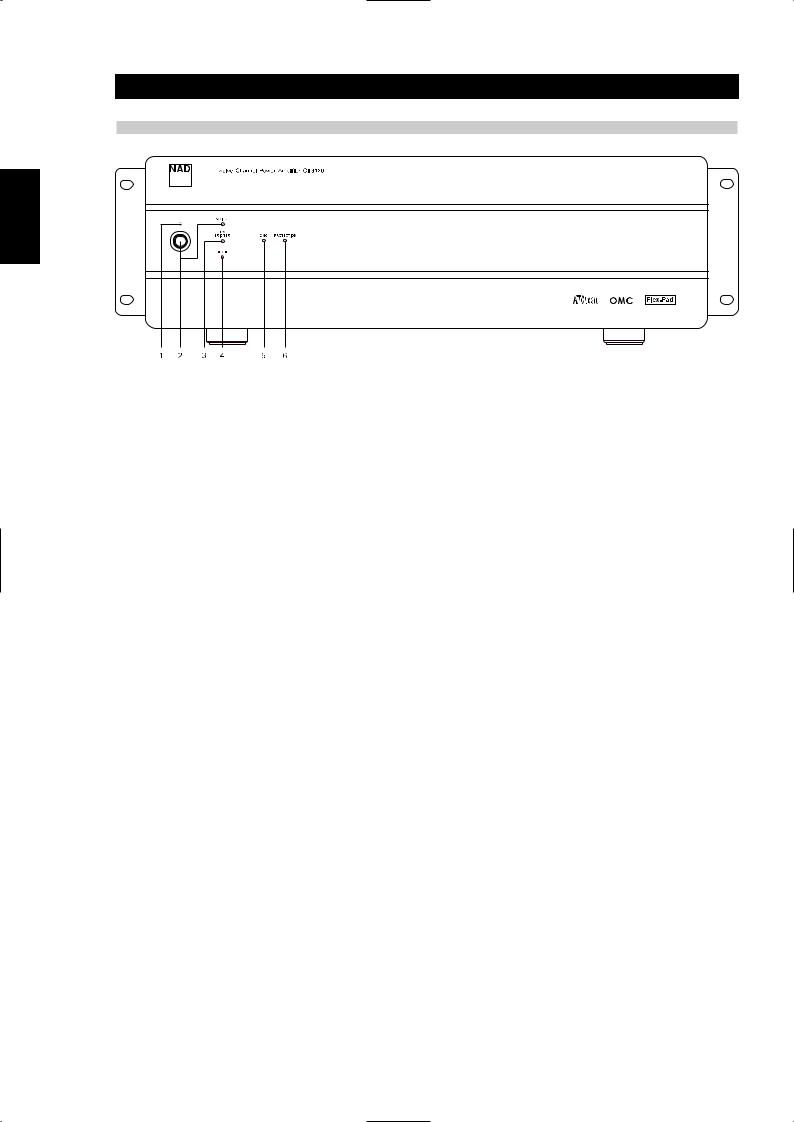
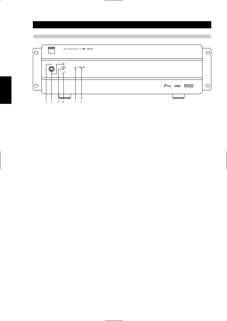
FRONT-PANEL CONTROLS AND INDICATORS
1The amber standby indicator LED over the front power switch must be on for the amplifier’s ATO Logic to function. This is achieved by having the “VACATION switch” in the ON position (refer to “RearPanel Controls and Connections”: VACATION switch section).
2The front-panel momentary-contact switch will power on, and place into standby, the NAD CI-series amplifier, denoted by the green LED labelled SWITCH. If you power on the amplifier via the front panel switch, the amber standby LED will turn off, and the SWITCH LED will turn green. Once you turn on the amplifier via the front-panel switch, only the front-panel switch can return the amplifier to standby state.
3The 12V-TRIGGER LED illuminates green when the amplifier switches from standby to power on state via the 12V input (refer to “RearPanel Controls and Connections”: 12V-TRIGGER INPUT section). Once you turn on the amplifier via the 12V-IN TRIGGER, only the absence of the 12V can return the amplifier to standby state.
4The SENSE LED illuminates green when the amplifier senses a signal greater than 20mV RMS on any of the amplifier inputs refer to “RearPanel Controls and Connections”: SLEEP/WAKE, SENSE/DEFEAT section). Once you turn on the amplifier via the SLEEP/WAKE sense logic, only the absence of a signal to all the amplifier’s inputs can return the amplifier to standby state.
5The OMC LED illuminates amber when the amplifier senses too much input signal or the load impedance drops below 2 to 3 Ohms, in either case a potential fault condition. When the fault condition is removed, the OMC LED will turn off, and the amplifier will return to normal operation.
6The PROTECTION LED illuminates red when the amplifier protects itself. For example, in the unlikely event of overheating, protection would be active and the protection LED would light red. The amplifier will stay in this state until one removes the fault condition. Once you remove the fault condition, the amplifier will come out of the protection state, and the amplifier will return to normal operation.
10
Installation
RACK-MOUNT INSTALLATION
Instructions for installation of the NAD CI-series amplifier are supplied with the Rack-Mounting hardware. Supplied with these instructions are 8 pieces of plastic bushings and 4 #10-32 bolts. These bolts with specifically designed plastic bushings are engineered to prevent ground loops and will support the weight of the NAD CI-series amplifier (see Figure 1).
89.0mm 3U mounting rail hole

Rack-mount bracket (Left) 


These shoulder washers are for use to rack-mount this unit.
If properly installed (See diagram), the washers will insulate the amplifier from the rack, preventing ground loops and hum, and will protect the unit’s surface from damage.
#10-32UNF- 3A
3A screw
screw


 4pcs required per unit


Mounting rack rail |
Shoulder washers |
EIA standard RS-310-C |
8pcs required per unit |
Figure 1
Since the NAD CI-series amplifier is a heavy amplifier, we recommend that you mount the NAD CI amplifier as close to the bottom of a rack as possible to promote a stable Rack-Mount installation.
The NAD CI-series amplifier takes up 3 standard, rack places on an EIA/IEC 19-inch rack. The NAD CI-series amplifier needs special consideration when rack-mounting to allow sufficient ventilation space all around the amplifier. Thus we recommend one should allow at least a one-rack-space below and above the amplifier as clearance, and that you allow more than 2 to 3 inches (5 to 7.5 cm) of space on all six sides of the NAD CI-series amplifier. Please refer to the “Ventilation Air Flow” specification found at the back of the instruction manual for maximum airflow requirements.
SHELF-MOUNT INSTALLATION
REMOVAL OF RACK-MOUNT BRACKETS
This unit may be installed on any level surface that is strong enough to support the amplifier’s weight. Please refer to the “Specifications” section at the back of the instruction manual for the exact weight of your NAD CI-series amplifier. Since the NAD CI-series amplifier was shipped with Rack-Mounting hardware attached, below is the removal procedure of the rack-mounting shelf brackets. We strongly recommend that you follow these procedures in order to prevent damage to the NAD CI amplifier or personal injury:
To detach the rack-mount bracket, place the amplifier on a flat surface, remove each set of three fixing screws on each side. Once the screws are removed, slide the bracket toward the rear of the amplifier to release it from its fittings in the chassis bottom surface and then slide the bracket toward you.
For self-mount installations of the NAD CI-series amplifier, we recommend that you do not place equipment on top of the amplifier. Leave at least 2 to 3 inches (5 to 7.5 cm) on all sides of the amplifier so that the NAD CI-series amplifier achieves adequate airflow. We strongly recommend that you do not block the side, top, back and front, airflow vents. Since its power transformer generates a significant magnetic hum field, a turntable (especially one with a magnetic pick-up cartridge) or a television should not be located adjacent to, directly above, or below the amplifier.
SVENSKA PORTUGUÊS ITALIANO ESPAÑOL NEDERLANDS DEUTSCH FRANÇAIS ENGLISH
11
SVENSKA PORTUGUÊS ITALIANO ESPAÑOL NEDERLANDS DEUTSCH FRANÇAIS ENGLISH
Installation
SPEAKER HOOK-UP
This amplifier is equipped with special high-current, binding-post speaker terminals to handle the highest peak-power levels that may occur with low-impedance speakers. At moments when the amplifier is producing maximum power, voltages of nearly 100V may be present on the speaker terminals, so plastic covers protect the terminals. To connect loudspeaker cables, first switch off the amplifier’s power by disconnecting the AC-power cord from the wall outlet.
Connect the wires from one of your speakers to the “+” and “-” terminals on the rear panel of the NAD CI-series amplifier. In each channel, the red terminal is the positive “+” output, and the black terminal is the negative “-” or “ground” terminal (see Figure 2).
Use heavy-duty (16-gauge/2mm or thicker) wire, especially with 4-ohm loudspeakers. Bare wires can be connected directly to the binding-post terminals. For a longer lasting and more corrosion resistant connection, you may install speaker cables with gold-plated connectors (pin connectors or spade lugs), or you can install such connectors on the wires yourself. Connections to each binding post may be made in the three ways described below.
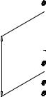
1Pin connectors: A pin connector is a slim metal shaft that is crimped or soldered onto the end of a wire. The threaded shaft of each binding post contains an opening that accepts pin connectors up to 3mm in diameter. Unscrew the plastic bushing on each terminal to expose the hole in the metal shaft. Insert the pin connector through the hole, and turn the bushing clockwise until it is tight (see Figure 2).
2Spade lugs: Unscrew the plastic bushing, insert the U-shaped spade lug into the oblong gap and tighten the bushing down on it (see Figure 2).
3Bare wires: Separate the two conductors of the cord (if they are supplied as a pair), and strip off a halfinch (1cm) of insulation from each. In each conductor, twist together the exposed wire strands. Unscrew the plastic bushings for “+” and “-”, insert the bare wire through the hole in the metal shaft, and tighten the plastic bushing until it grasps the wire securely (see Figure 2). Check to be sure that no loose strand of wire is touching the chassis or an adjacent terminal. Re-tighten the bushing after a week or so to make sure that any play that may have developed is eliminated.
Spade |
Wire |
Pin
Figure 2
12

Installation
PHASING
Stereo speakers must operate “in phase” with each other to produce a focused stereo blend and to reinforce rather than cancel each other’s output at low frequencies. An in-phase connection is assured if the red (positive) terminal on the amplifier is connected to the red (positive) terminal on the loudspeaker in each channel. If your speakers are easily moved, their phasing can easily be checked. Make the connections to both speakers, place the speakers face-to-face only a few inches apart, play some music, and listen. Then swap the connection of the two wires at the back of ONE of the speakers, and listen again. The connection that produces the fullest, most extended bass output is the correct one. Once you have determined the correct phasing, connect the wires securely to the speaker terminals, being careful not to leave any loose strands of wire that might touch the wrong terminal and create a partial short-circuit, then move the speakers to their intended locations.
If the speakers cannot easily be placed face-to-face, then phasing must rely on the “polarity” of the connecting wires. The speaker terminals on the amplifier are identified as red “+” and black “-” in each channel. The terminals at the rear of the speakers are also marked for polarity, either via red and black connectors or by labels: “+”, “1”, or “8 ohms” for positive, “-”, “0”, or “G” for negative. The red “+” terminal on the amplifier should be connected to the red (positive) terminal of the speaker in each channel. To facilitate this, the two conductors comprising the speaker wire in each channel are different, either in the colour of the wire itself (copper vs. silver) or in the presence of a small ridge or rib-pattern on the insulation of one conductor. Use this pattern to establish consistent wiring to both speakers of a stereo pair. Thus if you connect the copper-coloured wire (or ribbed insulation) to the “+” amplifier terminal in the Left channel, do the same in the Right channel. At the other end of the wire, if you connect the coppercoloured wire (or the ribbed insulation) to the red (positive) terminal on the left channel speaker, do the same at the right channel speaker.
NOTE
Safety organizations recommend that the speaker terminals of a very powerful amplifier should be covered. Potentially dangerous voltages are present on these terminals when the amplifier is producing maximum power. For your protection and in order to comply with these regulations, we have chosen speaker terminals of the very highest quality for the NAD CI-series amplifier. These terminals are covered by plastic bushings, which prevent the touching of metal parts.
SVENSKA PORTUGUÊS ITALIANO ESPAÑOL NEDERLANDS DEUTSCH FRANÇAIS ENGLISH
13
SVENSKA PORTUGUÊS ITALIANO ESPAÑOL NEDERLANDS DEUTSCH FRANÇAIS ENGLISH
Installation
ATTENTION INSTALLATION PERSONNEL
The following charts should be completely filled out and left in the possession of the NAD CI-series amplifier’s owner, to be used for future referral. Record all speaker locations, zones, controls, sources, and individual amplifier level settings.
NAD MODEL NUMBER
NUMBER of ZONES per AMPLIFIER
LOCATION of NAD CI-SERIES
AMPLIFIER
AMPLIFIER POWER CONTROL
SOURCE & DESCRIPTION OF POWER CONTROL
SOURCE FOR 12V-TRIGGER
EQUIPMENT FED BY NAD CI 12V–TRIGGER
SOURCE FOR SIGNAL SENSE
CLIENT CONFIGURATION
FLEX-PAD FOR THE FIRST 6 CHANNELS
SOURCE L
SOURCE R
DESTINATION L
DESTINATION R
DESTINATION MONO
FLEX-PAD FOR THE SECOND 6 CHANNELS
DESTINATION L
DESTINATION R
DESTINATION MONO
14
CLIENT CONFIGURATION (INPUT/CHANNEL DESTINATION)
MARK OFF INDIVIDUAL AMPLIFIER LEVEL SETTING FOR EACH CHANNEL BELOW
CHANNEL 1
SOURCE
ROOM LOCATION
SPEAKER DESCRIPTION
CHANNEL 2
SOURCE
ROOM LOCATION
SPEAKER DESCRIPTION
CHANNEL 3
SOURCE
ROOM LOCATION
SPEAKER DESCRIPTION
CHANNEL 4
SOURCE
ROOM LOCATION
SPEAKER DESCRIPTION
CHANNEL 5
SOURCE
ROOM LOCATION
SPEAKER DESCRIPTION
CHANNEL 6
SOURCE
ROOM LOCATION
SPEAKER DESCRIPTION
Installation
SVENSKA PORTUGUÊS ITALIANO ESPAÑOL NEDERLANDS DEUTSCH FRANÇAIS ENGLISH
15
SVENSKA PORTUGUÊS ITALIANO ESPAÑOL NEDERLANDS DEUTSCH FRANÇAIS ENGLISH
Installation
CLIENT CONFIGURATION (INPUT/CHANNEL DESTINATION CONTINUED)
MARK OFF INDIVIDUAL AMPLIFIER LEVEL SETTINGS FOR EACH CHANNEL BELOW:
CHANNEL 7
SOURCE
ROOM LOCATION
SPEAKER DESCRIPTION
CHANNEL 8
SOURCE
ROOM LOCATION
SPEAKER DESCRIPTION
CHANNEL 9
SOURCE
ROOM LOCATION
SPEAKER DESCRIPTION
CHANNEL 10
SOURCE
ROOM LOCATION
SPEAKER DESCRIPTION
CHANNEL 11
SOURCE
ROOM LOCATION
SPEAKER DESCRIPTION
CHANNEL 12
SOURCE
ROOM LOCATION
SPEAKER DESCRIPTION
16

|
|
|
|
Troubleshooting |
PROBLEM |
|
CAUSE |
|
SOLUTION |
|
|
|
|
|
No sound |
• |
Power AC-mains cable unplugged |
• |
Check if AC-mains cable is plugged in and |
|
|
|
|
power switched on |
|
|
|
|
|
|
• |
VACATION switch set to VACATION |
• |
Set the VACATION switch to ON |
|
|
|
|
|
|
• |
The Protection mode is engaged |
• |
Switch amplifier off via VACATION switch. Make |
|
|
|
|
sure ventilation slots on top, side, and back of the |
|
|
|
|
amplifier are not blocked. After amplifier has |
|
|
|
|
cooled down, switch the amplifier on |
|
|
|
|
|
|
• |
External fuse blown |
• |
Replace fuse |
|
|
|
|
|
|
|
|
• |
Consult dealer/installer |
|
|
|
|
|
No sound in one channel |
• |
Speaker not properly connected or damaged |
• |
Check all connections both at the speakers and |
|
|
|
|
at the amplifier |
|
|
|
|
|
|
• |
Input cable pulled loose or making poor contact |
• |
Check leads and Flex-Pad cables |
|
|
at Flex-Pad socket |
|
|
|
|
|
|
|
|
• |
Short-circuit or broken wire in a defective patch |
• |
Switch the amplifier to VACATION mode, check |
|
|
or speaker cable |
|
and replace cables if necessary |
|
|
|
|
|
Weak bass/ poor stereo image |
• |
Speakers wired out-of-phase |
• |
Reverse connections at the back of the suspect |
|
|
|
|
amplifier output |
|
|
|
|
|
|
|
|
• Check connections to all speakers in the affected |
|
|
|
|
|
zone/room |
|
|
|
|
|
Low or distorted sound in one zone/room |
• |
Shorted speaker cable to zone/room |
• |
Switch off amplifier via VACATION switch and |
and OMC LED on |
|
|
|
remove one at a time a pair of speaker cables |
|
|
|
|
from the amplifier, then switch the VACATION |
|
|
|
|
switch to the ON position and restore audio |
|
|
|
|
source. Continue this procedure until the OMC |
|
|
|
|
LED does not turn on. Replace the shorted |
|
|
|
|
speaker cable to the zone/room |
|
|
|
|
|
|
• |
Too high of an input level to one or more |
• |
Turn down the input level to the room/zone that |
|
|
amplifier channels |
|
may be suspect |
|
|
|
|
|
|
• |
Too low an impedance on one or more amplifier |
• |
Too many speakers connected to one channel, or |
|
|
zones/rooms |
|
incorrect speaker pad or matching transformer |
|
|
|
|
impedance settings. Remove some speakers or |
|
|
|
|
check speaker pad and/or documentation |
|
|
|
|
supplied from the speaker pad manufacturer for |
|
|
|
|
correct impedance settings |
• Damage to speaker pad. Replace speaker pad
SVENSKA PORTUGUÊS ITALIANO ESPAÑOL NEDERLANDS DEUTSCH FRANÇAIS ENGLISH
17

SVENSKA PORTUGUÊS ITALIANO ESPAÑOL NEDERLANDS DEUTSCH FRANÇAIS ENGLISH
Specifications
Power Rating
85 Watts continuous average power into 6 Ohms at any frequency between 20Hz and 20kHz with all channels driven at less than 0.03% THD.
86 Watts continuous average power into 4 Ohms at any frequency between 20Hz and 20kHz with all channels driven at less than 0.03% THD.
IM Distortion (SMPTE)
80 Watts into 6 Ohms |
< 0.03 % |
80 Watts into 4 Ohms |
< 0.03 % |
IM Distortion (CCIF, Any Combination from 1kHz to 20kHz)
80 Watts into 6 Ohms |
< 0.03 % |
80 Watts into 4 Ohms |
< 0.03 % |
THD + Noise at 1 Watt into 6 Ohms |
|
20Hz |
0.03 % |
1kHz |
0.03 % |
10kHz |
0.03 % |
20kHz |
0.03 % |
THD + Noise at 80 Watts into 6 Ohms |
|
20Hz |
0.03 % |
1kHz |
0.03 % |
10kHz |
0.03 % |
20kHz |
0.03 % |
Frequency Response @ 1 Watt into 6 Ohms |
|
10Hz to 20kHz |
+ 0.5, -1.0dB |
Power Bandwidth (-3dB) |
5Hz to 45kHz |
Gain |
28dB |
Amplifier Trimmer Adjustment Range |
14 ± 2 dB |
Damping Factor |
>30 |
Dynamic Headroom into 6 Ohms |
1.6dB |
OMC Activation |
< 3 Ohms across any speaker terminal |
ATO Logic |
|
SENSE Input Sensitivity |
>20mV rms |
12V Trigger Input Voltage Range |
10.0V to 20.0V DC, 100k Ohms |
12V Trigger Output Current |
25 ± 5mA, 470 Ohms |
Input Impedance |
25k Ohms |
Input Sensitivity |
|
80 Watt into 6 Ohms |
1V rms |
1 Watt into 6 Ohms |
114mV rms |
Damping Factor 20Hz to 20kHz |
< 31 |
Rise Time |
|
5kHz, 50V peak-to-peak square wave, |
|
20% to 80% |
4 µs |
Power Consumption (Continuous, All Channels Driven) |
|
Quiescent |
84/168VA |
Maximum |
960/1920VA |
80 Watts into 6 Ohms |
744/1488VA |
80 Watts into 4 Ohms |
900/1800VA |
GENERAL |
|
Power (available in 240V) |
120VAC/50-60Hz |
Ambient Operating Temperature |
< 100 °F (40 °C) |
Operating Temperature |
68 °F (20 °C) |
|
above ambient temperature |
Ventilation Air Flow |
150 cubic feet/minute maximum |
Net Chassis Dimensions |
17.2x5.3x17.8 inches (437x133x451 mm) |
|
or 3 rack heights |
Maximum Gross Dimensions |
18.9x19.0x5.7 inches (480.1x481.7x144.8 mm) |
|
(includes rack mounting hardware, |
|
feet and speaker terminals) |
Weight CI 9060, Packed |
55-60 lb (25-27 Kg), 75 lb (34 Kg) |
Weight CI 9120, Packed |
78-82 (35-37 Kg), 97 lb (44 Kg) |
18

Fuse Replacement Chart
FUSE REPLACEMENT - PLEASE NOTE CAREFULLY
The fuses listed in the chart below have been carefully selected and thoroughly tested to deliver optimal performance and still accomplish their protective functions. Replace the AC INPUT LINE FUSE only with one of the fuses listed in the chart. DO NOT USE ANY SUBSTITUTE FUSES OF DIFFERENT TYPES OR WITH DIFFERENT CURRENT RATINGS, TIME-CURRENT CURVES OR VALUES. Failure to observe this precaution may cause damage to the amplifier circuits, MAY CREATE A FIRE HAZARD AND/OR DEFEAT THE SAFETIES BUILT INTO THE AMPLIFIER, AND MAY VOID THE WARRANTY.
Model |
Bussman |
Littelfuse |
Bel |
9120 AH |
MDA-20/250V |
3AB 326020/250V |
N/A |
9060 AH |
MDA-12/250V |
3AB 326012/250V |
GSA 12/250 |
9120 C (1 & 2) |
MDA-10/250V |
3AB 326010/250V |
GSA 10/250 |
9060 C (1 & 2) |
MDA-6/250V |
3AB 326060/250V |
GSA 6/250 |
SVENSKA PORTUGUÊS ITALIANO ESPAÑOL NEDERLANDS DEUTSCH FRANÇAIS ENGLISH
19

2
ENGLISH |
FRANÇAIS |
DEUTSCH |
NEDERLANDS |
ESPAÑOL |
ITALIANO |
PORTUGUÊS |
SVENSKA |
Introduction
TABLE DES MATIÈRES
I Introduction . . . . . . . . . . . . . . . . . . . . . . . . . . . . . . . . . . . . . . . . . . . . . . . . . . . . . . . . . . . . . . .3-5
Consignes de Sécurité. . . . . . . . . . . . . . . . . . . . . . . . . . . . . . . . . . . . . . . . . . . . . . . . . . . . . . . . . 4
II Fonctionnement . . . . . . . . . . . . . . . . . . . . . . . . . . . . . . . . . . . . . . . . . . . . . . . . . . . . . . . . . .6-10
ATO Logic de NAD . . . . . . . . . . . . . . . . . . . . . . . . . . . . . . . . . . . . . . . . . . . . . . . . . . . . . . . . . . . 6
OMC de NAD. . . . . . . . . . . . . . . . . . . . . . . . . . . . . . . . . . . . . . . . . . . . . . . . . . . . . . . . . . . . . . . 7
Circuits de protection NAD . . . . . . . . . . . . . . . . . . . . . . . . . . . . . . . . . . . . . . . . . . . . . . . . . . . . . 7
III Installation . . . . . . . . . . . . . . . . . . . . . . . . . . . . . . . . . . . . . . . . . . . . . . . . . . . . . . . . . . . . .11-16
Montage en Châssis-Rack . . . . . . . . . . . . . . . . . . . . . . . . . . . . . . . . . . . . . . . . . . . . . . . . . . . . . 11
Montage sur Étagère . . . . . . . . . . . . . . . . . . . . . . . . . . . . . . . . . . . . . . . . . . . . . . . . . . . . . . . . 11
Branchement des haut-parleurs. . . . . . . . . . . . . . . . . . . . . . . . . . . . . . . . . . . . . . . . . . . . . . . . . 12
Configuration spécifique au client (entrée / destination des voies). . . . . . . . . . . . . . . . . . . . . . . . 14
Configuration spécifique au client (Flex-Pad) . . . . . . . . . . . . . . . . . . . . . . . . . . . . . . . . . . . . . . . 15
IV Dépannage . . . . . . . . . . . . . . . . . . . . . . . . . . . . . . . . . . . . . . . . . . . . . . . . . . . . . . . . . . . . . . .17
V Caractéristiques . . . . . . . . . . . . . . . . . . . . . . . . . . . . . . . . . . . . . . . . . . . . . . . . . . . . . . . . . . . .18
VI Tableau de remplacement des fusibles . . . . . . . . . . . . . . . . . . . . . . . . . . . . . . . . . . . . . . . . .19
ATTENTION : PERSONNEL D’INSTALLATION
Le matériel de fixation a été spécialement conçu pour l’Amplificateur NAD série CI. Nous déconseillons l’utilisation d’un autre type de matériel de fixation.
L’amplificateur NAD série CI étant d’une très grande puissance, les blocs d’alimentation sont lourds et plusieurs personnes seront peut-être nécessaires pour monter l’ensemble de l’amplificateur dans un châssis-rack.
NOTA
Lorsque l’amplificateur est posé sur une surface horizontale, sa masse doit toujours reposer sur ses pieds inférieurs. Il ne faut jamais poser l’amplificateur sur son panneau arrière, face parlante vers le haut. Si vous le faites, vous risquez d’endommager les connecteurs d’entrée-sortie.
L’amplificateur génère une quantité modérée de chaleur et nécessite donc une ventilation interne. Veillez donc à ce que les grilles d’entrée et de sortie d’air situées sur les panneaux supérieur, inférieur, latéraux et arrière, ne soient jamais obstruées par des papiers ou par tout autre objet.
NOTA
Pour éviter tout risque d’incendie ou de choc électrique, évitez toute pénétration de liquide ou d’humidité à l’intérieur de l’amplificateur. En cas de déversement accidentel d’un liquide dans l’appareil, coupez immédiatement l’alimentation électrique et débranchez le câble secteur de la prise murale.
N’ouvrez pas l’amplificateur et ne tentez jamais de le modifier ou de le réparer vous-même. Pour toute intervention, adressez-vous à un technicien qualifié.
Les caractéristiques ou la conception de ce matériel peuvent être modifiées sans préavis. Toutes les caractéristiques indiquées sont celles de l’appareil au moment de l’impression du présent document.
NAD®, OMC™, ATO Logic™, et Flex-Pad™ sont des marques déposées de NAD Electronics International, division de Lenbrook Industries Limited.
©2000, NAD Electronics International, division de Lenbrook Industries Limited
SVENSKA PORTUGUÊS ITALIANO ESPAÑOL NEDERLANDS DEUTSCH FRANÇAIS ENGLISH
3
SVENSKA PORTUGUÊS ITALIANO ESPAÑOL NEDERLANDS DEUTSCH FRANÇAIS ENGLISH
Introduction
EXPLICATION DES SYMBOLES GRAPHIQUES
Le symbole de l'éclair avec une flèche à son extrémité, dans un triangle équilatéral, a pour but d'avertir l'utilisateur de la présence d'une "tension électrique dangereuse" à l'intérieur de l'enceinte de l'appareil, qui peut être suffisamment puissante pour constituer un risque de choc électrique pour les personnes.
Le point d'exclamation dans un triangle équilatéral a pour but d'avertir l'utilisateur que la documentation livrée avec l'appareil contient des instructions importantes concernant l'utilisation et l'entretien.
PRÉCAUTIONS
Lisez attentivement l'ensemble des Instructions d'Utilisation avant de faire fonctionner l'appareil. Conservez les Instructions d'Utilisation afin de pouvoir vous y référer à une date ultérieure. Tous les avertissements et toutes les mises en garde imprimés dans les Instructions d'Utilisation et sur l'appareil luimême doivent être respectés. Il en est de même pour les recommandations suivantes concernant la sécurité.
INSTALLATION
1Eau et Humidité - Cet appareil ne doit pas être utilisé à proximité de l'eau, par exemple près d'une baignoire, d'un lavabo, d'une piscine, etc ...
2Chaleur - N'utilisez pas cet appareil à proximité d'une source de chaleur comme une bouche de chauffage, une cuisinière ou tout autre appareil dégageant de la chaleur. L'appareil ne doit pas être mis en présence de températures inférieures à 5 °C ou supérieures à 35 °C.
3Support - Posez l'appareil sur une surface plane et horizontale.
4Aération - L'appareil doit être installé dans un endroit où l'air peut circuler librement autour, afin de bien évacuer la chaleur dégagée. Prévoyez un dégagement de 10 cm derrière et au dessus de l'appareil
et de 5 cm de chaque côté. - Ne posez pas l'appareil sur un lit, un tapis ou une surface semblable, car cela boucherait les ouvertures d'aération sur la face inférieure. - N'installez pas l'appareil dans une bibliothèque fermée ou dans un rack hermétique, car la ventilation de l'appareil ne serait pas assurée correctement.
5 Pénétration de corps étrangers ou de liquides - Veillez à ce qu'aucun objet ni aucun liquide ne pénètre à l'intérieur de l'appareil à travers les ouvertures d'aération.
6Chariots et supports - Si vous placez ou installez l'appareil sur un support ou sur un chariot, les déplacements doivent être effectués en faisant très attention. Les arrêts brusques, les efforts excessifs ou les sols accidentés risqueraient de renverser le chariot et l'appareil.
7Fixation au mur ou au plafond - L'appareil ne doit pas être fixé au mur ou au plafond, à moins que cela ne soit prévu dans les Instructions de l'Utilisateur.
ATTENTION DANGER. POUR ÉVITER TOUT RISQUE D'INCENDIE OU DE CHOC ÉLECTRIQUE, N'EXPOSEZ JAMAIS CET APPAREIL A LA PLUIE OU A L'HUMIDITÉ.
Ce produit a été fabriqué de manière à être conforme aux exigences concernant les interférence radio des
DIRECTIVES CEE 89/68/EEC et 73/23/EEC.
4

Introduction
ALIMENTATION ÉLECTRIQUE
1Sources d'alimentation - Ce produit doit obligatoirement être alimenté par une source du type indiqué dans les Instructions d'Utilisation et sur l'appareil lui-même.
2Polarité - Pour des raisons de sécurité, il se peut que cet appareil soit équipé d'une prise secteur alternatif avec système de détrompage interdisant tout branchement dans le "mauvais sens". Si la fiche n'entre pas (ou pas complètement) dans la prise murale, essayez de la brancher dans l'autre sens. Si elle n'entre toujours pas, appelez un électricien qualifié pour faire réparer ou remplacer votre prise murale. Afin de ne pas détériorer le dispositif de sécurité de la prise détrompée, n'essayez pas de la brancher de force dans la prise murale.
3Cordon d'alimentation secteur - Lorsque vous débranchez le cordon d'alimentation secteur, tirez sur la fiche secteur et non sur le cordon.
•Ne touchez jamais la fiche ou la prise secteur si vous avez les mains mouillées, car vous risqueriez de subir un choc électrique ou de provoquer un incendie.
•Les câbles d'alimentation ne doivent pas passer dans des endroits où ils risquent d'être piétinés ou pincés ou tordus excessivement. Faites particulièrement attention à ces détails pour ce qui concerne le câble entre l'appareil et la prise murale.
•Évitez de surcharger les prises de secteur murales et/ou les rallonges, car cela risquerait d'entraîner un incendie ou de provoquer un choc électrique.
4Rallonge électrique - Afin de contribuer à éviter les chocs électriques, ne branchez jamais une fiche secteur détrompée sur une rallonge électrique, une embase ou une quelconque autre source de courant si la fiche ne peut pas être complètement enfoncée dans la prise : les broches de la fiche doivent être inaccessibles.
5Lorsque l'appareil n'est pas utilisé - Débranchez le cordon secteur de la prise murale si l'appareil ne va pas être utilisé pendant plusieurs mois. Lorsque le cordon reste branché, un courant faible est débité par l'appareil, même s'il est hors tension.
ATTENTION
En cas de réglage ou de modification dont la conformité n'aura pas été expressément approuvée par le fabricant, le droit de l'utilisateur de faire fonctionner l'appareil risque d'être retiré.
DÉTÉRIORATIONS NÉCESSITANT UNE INTERVENTION
Dans les cas suivants, faites réparer l'appareil par un technicien de service après vente qualifié :
•Détérioration de la fiche d'alimentation secteur.
•Pénétration de corps étrangers ou de liquides à l'intérieur de l'appareil.
•L'appareil a été exposé à la pluie ou à l'humidité - L'appareil semble ne pas fonctionner correctement.
•Les performances de l'appareil se sont sensiblement détériorées.
•L'appareil a subi une chute, ou le boîtier a été endommagé.
NE TENTEZ AUCUNE RÉPARATION VOUS-MÊME.
INFORMATIONS PARTICULIÈRES
Pour simplifier vos démarches, notez ci-dessous le numéro de modèle et le numéro de série de votre appareil (vous les trouverez à l'arrière de l'appareil lui-même). Veuillez les rappeler lorsque vous contacterez votre revendeur, en cas de problème.
N° de Modèle :
N° de Série :
SVENSKA PORTUGUÊS ITALIANO ESPAÑOL NEDERLANDS DEUTSCH FRANÇAIS ENGLISH
5

SVENSKA PORTUGUÊS ITALIANO ESPAÑOL NEDERLANDS DEUTSCH FRANÇAIS ENGLISH
Fonctionnement
ATO LOGIC DE NAD
La mise en marche de l’amplificateur série CI peut être effectuée de trois façons distinctes, pour une flexibilité totale de la chaîne : 1) à l’aide de l’interrupteur de la face parlante, 2) via le circuit d’ASSERVISSEMENT 12 V [12V-TRIGGER], ou 3) via un circuit de détection de signal VEILLE/ÉVEIL [SLEEP/WAKE]. La commande MARCHE/ARRÊT [ON/OFF] est gérée par le circuit Logique de Mise en Marche Automatique [Automated Turn-On logic - ATO Logic], qui nécessite que l’on remette l’amplificateur en mode veille en utilisant la même commande que pour sa mise en marche. Autrement dit, si vous mettez l’amplificateur en marche grâce à un signal de commande 12 V, il est impossible de le remettre en veille à l’aide de l’interrupteur sur la face parlante ; l’amplificateur doit obligatoirement attendre la disparition du signal de commande 12 V. Dans la pratique, vous n’utiliserez qu’une seule de ces trois méthodes une fois l’installation de votre amplificateur NAD série CI terminée.
TABLEAU DE LOGIQUE DE MISE EN MARCHE AUTOMATIQUE [ATO LOGIC]
|
LED orange au |
|
|
|
|
INTERRUPTEUR [“SWITCH”] |
dessus de |
LED verte |
LED verte |
|
|
l’interrupteur de la |
INTERRUPTEUR |
d’ASSERVISSEMENT |
LED verte CAPTEUR |
||
|
|||||
|
face parlante |
[“SWITCH”] |
12 V [12V-TRIGGER] |
[SENSE] |
|
Interrupteur VACANCES [VACATION] |
|
|
|
|
|
en position “VACANCES” |
ÉTEINTE |
ÉTEINTE |
ÉTEINTE |
ÉTEINTE |
|
[“VACATION”] |
|
|
|
|
|
Interrupteur VACANCES [VACATION] |
ALLUMÉE |
ÉTEINTE |
ARRÊT |
ÉTEINTE |
|
en position MARCHE [ON] |
|||||
|
|
|
|
||
|
|
|
|
|
|
Impulsion sur le bouton interrupteur |
|
|
|
|
|
d’alimentation sur la face parlante, |
|
|
|
|
|
alors que l’interrupteur VACANCES |
ÉTEINTE |
ALLUMÉE |
ÉTEINTE |
ÉTEINTE |
|
[VACATION] est en position MARCHE |
|
|
|
|
|
[ON] |
|
|
|
|
|
Nouvelle impulsion sur le bouton |
|
|
|
|
|
interrupteur d’alimentation sur la face |
|
|
|
|
|
parlante, alors que l’interrupteur |
ALLUMÉE |
ÉTEINTE |
ÉTEINTE |
ÉTEINTE |
|
VACANCES [VACATION] est en |
|
|
|
|
|
position MARCHE [ON] |
|
|
|
|
|
d’ASSERVISSEMENT 12V |
LED orange au |
|
|
|
|
dessus de |
LED verte |
LED verte |
|
||
[12V-TRIGGER] |
l’interrupteur de la |
INTERRUPTEUR |
d’ASSERVISSEMENT |
LED verte CAPTEUR |
|
|
face parlante |
[“SWITCH”] |
12 V [12V-TRIGGER] |
[SENSE] |
|
Interrupteur VACANCES [VACATION] |
|
|
|
|
|
en position “VACANCES” |
ÉTEINTE |
ÉTEINTE |
ÉTEINTE |
ÉTEINTE |
|
[“VACATION”] |
|
|
|
|
|
Interrupteur VACANCES [VACATION] |
ALLUMÉE |
ÉTEINTE |
ÉTEINTE |
ÉTEINTE |
|
en position MARCHE [“ON”] |
|||||
|
|
|
|
||
|
|
|
|
|
|
ENTRÉE ASSERVISSEMENT 12 V = 0 V |
|
|
|
|
|
avec Interrupteur VACANCES |
ALLUMÉE |
ÉTEINTE |
ÉTEINTE |
ÉTEINTE |
|
[VACATION] en position MARCHE |
|||||
|
|
|
|
||
[“ON”] |
|
|
|
|
|
ENTRÉE ASSERVISSEMENT 12 V = 12 |
|
|
|
|
|
V avec Interrupteur VACANCES |
ÉTEINTE |
ÉTEINTE |
ALLUMÉE |
ÉTEINTE |
|
[VACATION] en position MARCHE |
|||||
|
|
|
|
||
[“ON”] |
|
|
|
|
|
|
LED orange au |
|
|
|
|
VEILLE/ÉVEIL [SLEEP/WAKE] |
dessus de |
LED verte |
LED verte |
|
|
l’interrupteur de la |
INTERRUPTEUR |
d’ASSERVISSEMENT |
LED verte CAPTEUR |
||
|
|||||
|
face parlante |
[“SWITCH”] |
12 V [12V-TRIGGER] |
[SENSE] |
|
Interrupteur VACANCES [VACATION] |
|
|
|
|
|
en position “VACANCES” |
ÉTEINTE |
ÉTEINTE |
ÉTEINTE |
ÉTEINTE |
|
[“VACATION”] |
|
|
|
|
|
Interrupteur VACANCES [VACATION] |
ALLUMÉE |
ÉTEINTE |
ÉTEINTE |
ÉTEINTE |
|
en position “MARCHE” [“ON”] |
|||||
|
|
|
|
||
|
|
|
|
|
|
Sélecteur VEILLE/ÉVEIL - CAPTEUR |
|
|
|
|
|
INHIBÉ [SLEEP/WAKE - SENSE |
|
|
|
|
|
DEFEAT] en position CAPTEUR INHIBÉ |
ALLUMÉE |
ÉTEINTE |
ÉTEINTE |
ÉTEINTE |
|
[SENSE DEFEAT) avec interrupteur |
|||||
|
|
|
|
||
VACANCES [VACATION] en position |
|
|
|
|
|
“MARCHE” [“ON”] |
|
|
|
|
|
Sélecteur VEILLE/ÉVEIL - CAPTEUR |
|
|
|
|
|
INHIBÉ [SLEEP/WAKE - SENSE |
|
|
|
|
|
DEFEAT] en position VEILLE/ÉVEIL |
|
|
|
|
|
[SLEEP/WAKE] et n’importe quelle |
ÉTEINTE |
ÉTEINTE |
ÉTEINTE |
ALLUMÉE |
|
entrée source est à plus de 20mV, |
|||||
|
|
|
|
||
avec interrupteur VACANCES |
|
|
|
|
|
[VACATION] en position “MARCHE” |
|
|
|
|
|
[“ON”] |
|
|
|
|
|
|
|
|
|
|
6

Fonctionnement
OMC DE NAD
Le Circuit de Gestion Sorties [Output Management Circuit (OMC)] spécifique à NAD garantit la disponibilité de toute la puissance de l'amplificateur, quelle que soit l'impédance de charge à la sortie (dans des limites raisonnables). L'OMC assure la commande des différentes voies de l'amplificateur en gérant le niveau d'entrée (en cas de signal d'entrée délibérément excessif) et/ou le niveau de sortie (en cas de défaillance au niveau du haut-parleur ou de son câble. Cela permet non seulement de protéger l'amplificateur, mais aussi d'empêcher un échauffement excessif des charges connectées à l'amplificateur, ce qui constitue un facteur important pour assurer la fiabilité d'une chaîne complète. Lorsque l'OMC détecte une situation de panne potentielle et qu'il commence à limiter le débit de courant, une LED orange s'allume sur la face parlante pour en avertir l'installateur ou le propriétaire d'un problème dans la chaîne. Lorsque l'OMC est actif, l'amplificateur continue à fonctionner sans distorsion mais le niveau de puissance sera peut-être réduit sur la voie affectée par le problème. Si la panne persiste et que l'impédance tombe à une valeur insuffisante, les voies affectées activent les Circuits de Protection NAD (reportez-vous à la section concernant les Circuits de Protection NAD, ci-après).
CIRCUITS DE PROTECTION NAD
Chaque fois que nous avons pris une décision concernant la conception de ce produit, tant électronique que mécanique, l'objectif primaire a toujours été la fiabilité totale de l'amplificateur. Un circuit de protection à réarmement automatique fait aussi partie de la conception de l'Amplificateur série CI. Le circuit de protection ultrarapide s'active instantanément si l'amplificateur chauffe excessivement ou est confronté à état de court circuit. Une LED sur la face parlante s'allume quand le circuit de Protection a été activé. Seuls les amplificateurs affectés par un état de court-circuit seront en mode Protection ; toutes les autres voies continueront à fonctionner normalement. Dès que les conditions normales se sont rétablies, les voies affectées sont remises à zéro. Dans le cas peu probable d'une panne de l'amplificateur, l'Amplificateur série CI est conçu pour permettre une réparation facile à domicile car tous les circuits d'amplification sont montés sur des modules enfichables.
SVENSKA PORTUGUÊS ITALIANO ESPAÑOL NEDERLANDS DEUTSCH FRANÇAIS ENGLISH
7

SVENSKA PORTUGUÊS ITALIANO ESPAÑOL NEDERLANDS DEUTSCH FRANÇAIS ENGLISH
Fonctionnement
COMMANDES ET BRANCHEMENTS SUR LE PANNEAU ARRIÈRE
1 |
2 |
3 |
4 |
1 |
2 |
3 |
5 |
4 |
10 |
11 |
9 |
8 |
7 |
6 |
1Il existe une commande de réglage de VOIE pour chaque voie de l’amplificateur. Chaque commande de réglage permet d’atténuer chaque entrée depuis une valeur minimum à la valeur MAXI [MAX] (environ -13 dB à 0.0 dB). Nous avons défini la plage de réglage de manière à ce qu’elle soit suffisante pour accorder la sensibilité des différents haut-parleurs, qu’ils soient répartis dans plusieurs pièces ou installés dans la même pièce. Cette commande de réglage est conçue uniquement pour apparier la sensibilité ; il ne s’agit pas d’une commande de volume sonore. Il est peu probable que vous ayez à modifier le réglage de ces commandes après avoir terminé l’installation de votre chaîne, ce qui explique pourquoi elles se trouvent à l’arrière de l’amplificateur.
2Chaque ENTRÉE ET SORTIE DE VOIE [CHANNEL INPUT OUTPUT] est une connexion directe, ce qui fait que l’impédance source de chaque entrée de voie est identique à l’impédance de la sortie. La conception spéciale des câbles RCA de NAD, fournis avec l’amplificateur NAD série CI, permettent d’alimenter jusqu’à 6 voies à partie d’une seule voie de SORTIE Flex-Pad STÉRÉO et MONO, sans dégradation de la qualité du son. À titre d’exemple, il est possible de relier la SORTIE Droite [OUT Right] du Flex-Pad à l’ENTRÉE VOIE 1 [CHANNEL 1 INPUT], puis la SORTIE VOIE 1 [CHANNEL 1 OUTPUT] à l’ENTRÉE VOIE 2 [CHANNEL 2 INPUT], la SORTIE VOIE 2 [CHANNEL 2 OUTPUT] à l’ENTRÉE VOIE 3 [CHANNEL 3 INPUT], et ainsi de suite jusqu’à six voies d’entrées. Les câbles RCA NAD série CI sont des câbles hautes performances, spécialement conçus pour avoir une capacité électrique minimale.
Nous vous déconseillons d’utiliser des câbles de liaison RCA autres que les câbles de liaison RCA NAD fournis avec l’amplificateur NAD série CI ; l’utilisation de câbles d’un type différent pourrait entraîner une perte importante de la fidélité musicale, ou d’autres types de problèmes.
3La SORTIE MONO Flex-Pad [Flex-Pad MONO OUT] est la somme des entrées stéréophoniques droite et gauche, avec une impédance de sortie de 75 ohms. Nous vous déconseillons de piloter plus de 6 entrées d’amplificateur à partir de cette source de SORTIE MONO.
4Les SORTIES STÉRÉO Flex-Pad [Flex-Pad STEREO OUT] droite et gauche constituent un tampon stéréophonique avec une impédance de 75 Ohms par sortie, capable de piloter jusqu’à 6 entrées d’amplificateur NAD série CI par sortie. Nous vous déconseillons de piloter plus de 6 entrées d’amplificateur par sortie Flex-Pad.
5Les ENTRÉES STÉRÉO Flex-Pad [Flex-Pad STEREO IN] droite et gauche sont des entrées haute impédance spécialement conçues pour recevoir les sorties d’un préamplificateur ou d’un processeur de cinéma à domicile. Nous vous recommandons vivement de connecter ces entrées à un appareil qui n’est pas doté d’une commande de volume !
6Le sélecteur VACANCES [VACATION] est la principale commande marche/arrêt de l’amplificateur. Lorsque l’interrupteur est en position Marche, l’amplificateur est en veille et la LED orange au dessus du bouton Marche/Arrêt de la face parlante s’allume. Si l’amplificateur doit rester inutilisé pendant une longue période, mettez le sélecteur VACANCES en position VACANCES [VACATION].
7La logique du sélecteur VEILLE/ÉVEIL - CAPTEUR INHIBÉ [SLEEP/WAKE, SENSE/DEFEAT] gère l’état de veille/marche de l’amplificateur en fonction de l’absence ou de la présence d’un signal audio sur les entrées Flex-Pad ou sur les voies d’entrée de l’amplificateur. Le sélecteur VEILLE/ÉVEIL - CAPTEUR INHIBÉ doit être en position VEILLE/ÉVEIL [SLEEP/WAKE] afin de pouvoir utiliser cette logique. Lorsque sélecteur VEILLE/ÉVEIL - CAPTEUR INHIBÉ est en position CAPTEUR INHIBÉ [SENSE/DEFEAT], cette commande logique est désactivée.
8
Fonctionnement
Lorsque le sélecteur est en position VEILLE/ÉVEIL [SLEEP/WAKE], l’amplificateur NAD série CI passe instantanément en mode marche, à partir du mode veille, dès qu’il détecte un signal sur une voie quelconque, ce qui est indiqué par l’allumage d’une LED verte CAPTEUR [SENSE] sur la face parlante (signal d’entrée supérieur à environ 20mV eff.). Si tous les signaux audio sont absents pendant environ 5 minutes, l’amplificateur repasse automatiquement en mode Veille, ce qui est indiqué par l’extinction de la LED CAPTEUR [SENSE] et l’allumage de la LED orange au dessus du bouton Marche/Arrêt de la face parlante.
Lorsque le sélecteur est en position CAPTEUR INHIBÉ [SENSE/DEFEAT], l’amplificateur ne s’allume pas même si un signal est présent sur l’entrée de l’une des voies ou sur une entrée Flex-Pad.
8Les connecteurs d’ENTRÉE et de SORTIE ASSERVISSEMENT 12 V [12VTRIGGER IN & OUT] sont des jacks phono mono miniatures de 3,5 mm, dont la broche intérieure sert respectivement de capteur de signal 12 V et de sortie de signal 12 V. Nous recommandons l’utilisation d’un câble blindé de bonne qualité pour relier les jacks mono de 3,5 mm, de manière à éviter l’allumage intempestif de l’amplificateur en cas d’interférences électromagnétiques provenant d’appareils électroniques proches.
L’ENTRÉE ASSERVISSEMENT 12 V [12V-TRIGGER IN] vous permet d’assurer la mise en marche de l’amplificateur NAD série CI, depuis son état de veille, grâce à un signal 12 V. Ce signal 12 V doit être continu afin de maintenir l’amplificateur sous tension. Dès que vous enlevez le signal 12 V, l’amplificateur revient en mode veille.
La SORTIE ASSERVISSEMENT 12 V [12V-TRIGGER OUT] vous permet de commander d’autres produits équipés d’un capteur 12 V, à partir de l’amplificateur NAD série CI. La SORTIE ASSERVISSEMENT 12 V est présente en permanence lorsque l’amplificateur NAD série CI est et Marche ; elle est absente lorsqu’il est en état de Veille ou en état VACANCES [VACATION].
NOTES
•Vérifiez les caractéristiques de l’entrée asservissement de l’autre appareil, afin de vous assurer qu’elles sont compatibles avec celles de l’amplificateur NAD série CI.
•Toutes les entrées et sorties ASSERVISSEMENT 12 V [12V-TRIGGER] des autres appareils NAD possédant une fonction d’ASSERVISSEMENT 12 V [12V-TRIGGER] sont entièrement compatibles avec les ENTRÉES/SORTIES [IN/OUT] de l’ASSERVISSEMENT 12 V [12VTRIGGER] de l’amplificateur NAD série CI.
•Avant de réaliser un quelconque branchement à une entrée ou à une sortie d’ASSERVISSEMENT 12 V [12V-TRIGGER), assurez-vous que tous les appareils sont débranchés du secteur.
•En cas de doute au sujet des branchements, de l’installation et/ou du fonctionnement des branchements d’ENTRÉES-SORTIES [IN/OUT] de l’ASSERVISSEMENT 12 V [12V-TRIGGER], consultez votre revendeur NAD ou votre représentant local.
•Si vous ne respectez pas les consignes ci-dessus, vous risquez d’endommager l’amplificateur NAD série CI et/ou les éventuels appareils auxiliaires connectés à celui-ci.
9Un jeu de bornes de haut-parleurs est prévu sur chaque voie de l’amplificateur. Ces bornes sont repérées “+” et “-” pour indiquer leur polarité.
10Il existe deux types de cordons d’alimentation secteur. Reportez-vous aux figures ci-dessous pour le type qui correspond à votre amplificateur NAD série CI :
Avant de brancher le cordon secteur à une prise murale, vérifiez que toutes les entrées/sorties ont été préalablement connectées. Débranchez toujours le cordon secteur de la prise murale avant de déconnecter un quelconque câble de l’Amplificateur série CI. S’il est indispensable d’utiliser une rallonge, choisissez une rallonge grande puissance du type utilisé pour les gros appareils ménagers, comme par exemple une rallonge secteur pour climatiseur (section 2 mm_). Nous vous déconseillons vivement de relier le câble secteur de l’amplificateur aux prises secteur “accessoires” à l’arrière d’un préamplificateur. Ce type de prise n’est pas conçu pour fournir la grande puissance requise par l’amplificateur NAD série CI.
11Près de l’implantation du câble secteur se trouve un porte-fusible. Dans le cas improbable où il serait nécessaire de remplacer le fusible, débranchez d’abord le cordon secteur de la prise murale. Débranchez ensuite tous les câbles reliés à l’amplificateur. Le fusible de rechange doit impérativement être du même type et de la même taille que le fusible d’origine. Reportez-vous aux “CARACTÉRISTIQUES, Modèles NAD CI 9060 et CI 9120” sur la couverture arrière de ce manuel, pour connaître le calibre, le type et la taille du fusible à utiliser.
ATTENTION
Si vous ne remplacez pas le fusible par un fusible dont le calibre, le type et la taille correspondent exactement aux valeurs données dans le tableau intitulé “REMPLACEMENT DU FUSIBLE - VEUILLEZ LIRE ATTENTIVEMENT”, qui se trouve sur la couverture arrière de ce manuel d’instruction, section “Tableau de remplacement du fusible”, le fusible neuf pourrait claquer ou l’amplificateur pourrait subir des dommages.
SVENSKA PORTUGUÊS ITALIANO ESPAÑOL NEDERLANDS DEUTSCH FRANÇAIS ENGLISH
9
SVENSKA PORTUGUÊS ITALIANO ESPAÑOL NEDERLANDS DEUTSCH FRANÇAIS ENGLISH
Fonctionnement
COMMANDES ET INDICATIONS SUR LA FACE PARLANTE
1La LED orange de veille, située au dessus du bouton interrupteur Marche/Arrêt, doit être allumée pour que la logique ATO Logic puisse fonctionner. Pour cela, l’interrupteur “VACANCES” [“VACATION”] doit être en position MARCHE [ON] (reportez-vous à la rubrique “Commandes et branchements sur le panneau arrière” : section sélecteur VACANCES [VACATION]).
2Le bouton interrupteur à impulsion de la face parlante met l’amplificateur NAD série CI en marche ou en mode Veille, suivant l’allumage ou l’extinction de la LED verte repérée INTERRUPTEUR [SWITCH]. Si vous mettez l’amplificateur sous tension à l’aide de l’interrupteur de la face parlante, la LED orange de veille s’éteint et la LED INTERRUPTEUR [SWITCH] s’allume en vert. Après avoir mis l’amplificateur sous tension à l’aide de l’interrupteur de la face parlante, vous ne pourrez le remettre en état de veille qu’à l’aide de ce même bouton.
3La LED d’ASSERVISSEMENT 12 V [12V-TRIGGER] s’allume en vert lorsque l’amplificateur passe du mode veille en mode marche suite à la présence d’un signal sur l’entrée 12 V (reportez-vous à la rubrique “Commandes et branchements sur le panneau arrière” : section ASSERVISSEMENT 12 V [12V-TRIGGER INPUT]). Après avoir mis l’amplificateur sous tension via l’ENTRÉE ASSERVISSEMENT 12 V [12V-IN TRIGGER], vous ne pourrez le remettre en état de veille qu’en faisant disparaître le signal 12 V.
4La LED CAPTEUR [SENSE] s’allume lorsque l’amplificateur reçoit un signal supérieur à 20mV eff. sur l’une de ses entrées (reportez-vous à la rubrique “Commandes et branchements sur le panneau arrière” : section VEILLE/ÉVEIL - CAPTEUR INHIBÉ [SLEEP/WAKE, SENSE/DEFEAT]). Après avoir mis l’amplificateur sous tension via la logique de détection VEILLE/ÉVEIL [SLEEP/WAKE], vous ne pourrez le remettre en état de veille qu’en faisant disparaître les signaux sur toutes les entrées de l’amplificateur.
5La LED OMC s’allume en orange lorsque l’amplificateur détecte un signal d’entrée excessif, ou que l’impédance d’entrée tombe en dessous de 2 ou 3 Ohms, les deux cas étant des indications de défaillance possible. Dès que l’état de défaillance disparaît, la LED OMC s’éteint et l’amplificateur retrouve son fonctionnement normal.
6La LED de PROTECTION s’allume en rouge lorsque l’amplificateur se met en autoprotection. Par exemple, dans le cas improbable d’un échauffement excessif, l’autoprotection s’active et la LED rouge s’allume. L’amplificateur reste dans cet état jusqu’à ce que l’état de défaillance soit corrigé. Dès que vous avez éliminé la cause de la défaillance, l’amplificateur sort de son état d’autoprotection et revient en état de fonctionnement normal.
10
Installation
MONTAGE EN CHÂSSIS-RACK
Les instructions concernant l’installation de l’amplificateur NAD série CI sont fournies avec le matériel de Montage en Châssis-Rack. Avec ces instructions, vous trouverez 8 bagues en plastique et 4 boulons #1032. Ces boulons, avec leur bague de conception spéciale, sont prévus pour éviter les rebouclages électriques par le châssis et permettent de supporter le poids de l’amplificateur NAD série CI (Cf. Figure 1).
Trou sur rail de fixation 3U - 88,0 mm

CONSOLE DE FIXATION
SUR CHÂSSIS-RACK
CES RONDELLES ÉPAULÉES SONT DESTINÉES À
PERMETTRE LE MONTAGE DE CET APPAREIL SUR
UN CHÂSSIS-RACK
CORRECTEMENT INSTALLÉES (REPORTEZ-VOUS AU
SCHÉMA), CES RONDELLES ASSURERONT
L'ISOLATION DE L'AMPLIFICATEUR PAR RAPPORT
AU CHÂSSIS-RACK, DE MANIÈRE À ÉVITER TOUT
REBOUCLAGE PAR LA MASSE ET TOUT 


BOURDONNEMENT. DE PLUS, ELLES ÉVITERONT DE
MARQUER LA SURFACE DE L'APPAREIL LORS DE
SA FIXATION
VIS N° 10-32UNF-3A


 4 vis
4 vis requises par appareil

RAIL DU CHÂSSIS-RACK |
|
RONDELLES ÉPAULÉES |
EIA Standard RS-310-C |
|
8 rondelles requises par appareil |
|
|
|
Figure 1
L’amplificateur NAD série CI est un amplificateur lourd, aussi nous vous recommandons de monter cet amplificateur aussi près que possible du bas du châssis-rack afin que l’ensemble du rack soit bien stable. L’amplificateur NAD série CI occupe jusqu’à 3 emplacements standards sur un châssis-rack EIA/IEC 19 pouces. L’amplificateur NAD série CI demande une attention toute particulière lors de son montage en châssis-rack, car il faut prévoir un volume d’aération suffisamment grand tout autour de l’appareil. Nous vous recommandons donc de laisser libre au moins un emplacement de châssis au dessus et en dessous de l’amplificateur, et de prévoir un dégagement d’au moins 5 à 7,5 cm sur les six faces de l’amplificateur NAD série CI. Reportez-vous à la caractéristique “Débit d’Air de Ventilation” à l’arrière de ce Manuel d’Instruction, pour connaître le débit d’air maximum exigé.
MONTAGE SUR ÉTAGÈRE
DÉPOSE DES CONSOLES DE MONTAGE EN CHÂSSIS-RACK
Vous pouvez poser cet appareil sur n’importe quelle surface horizontale suffisamment robuste pour supporter son poids. Reportez-vous à la section “Caractéristiques” sur la couverture arrière de ce Manuel d’Instruction, pour connaître le poids exact de votre amplificateur NAD série CI. L’amplificateur NAD série CI est livré équipé de ses pièces de montage en châssis-rack ; les instructions ci-dessous vous permettront de déposer les consoles de montage en châssis-rack. Nous vous conseillons vivement de suivre ces instructions afin d’éviter toute détérioration de l’amplificateur NAD CI, ou tout risque de blessure corporelle:
Pour détacher la console de montage en châssis-rack, posez l’amplificateur sur une surface horizontale, puis déposez chaque ensemble de trois vis de fixation sur chaque côté de l’appareil. Après avoir déposé les vis, glissez la console vers l’arrière pour la dégager de ses fixations sur la face inférieure du boîtier, puis faites glisser la console vers vous.
Pour les installations autonomes de l’amplificateur NAD série CI, nous vous recommandons de ne poser aucun appareil sur l’amplificateur. Prévoyez un dégagement d’au moins 5 à 7,5 cm sur toutes les faces de l’amplificateur, de manière à ce que l’amplificateur NAD série CI reçoive un débit d’air suffisant. Nous vous recommandons fortement de ne pas obstruer les ouïes de ventilation sur les faces latérales, supérieure, arrière ou avant. Comme son transformateur génère un bourdonnement de champ magnétique important, il ne faut pas placer une platine tourne-disque (surtout si elle a une tête magnétique) ou un téléviseur à côté de l’amplificateur, ou juste au dessus ou en dessous de celui-ci.
SVENSKA PORTUGUÊS ITALIANO ESPAÑOL NEDERLANDS DEUTSCH FRANÇAIS ENGLISH
11
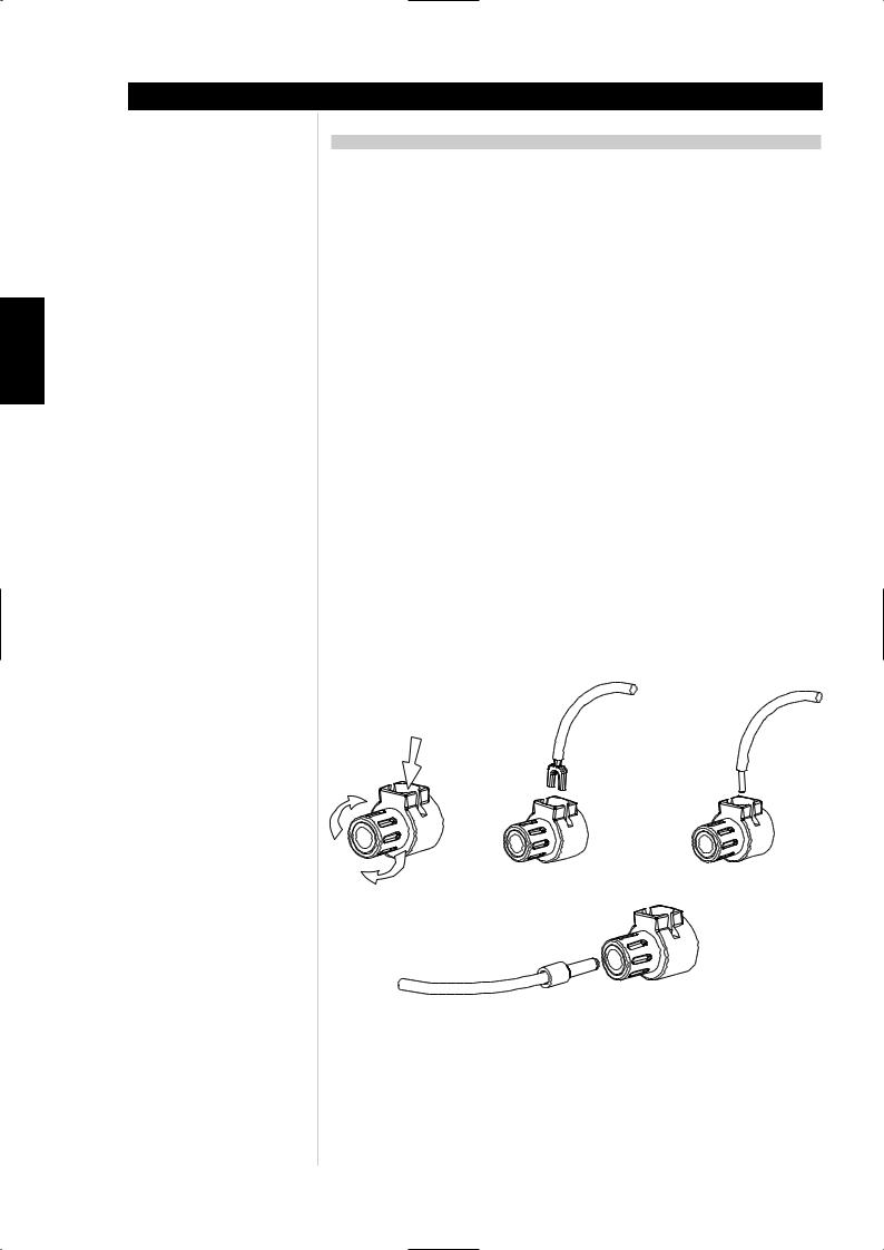
SVENSKA PORTUGUÊS ITALIANO ESPAÑOL NEDERLANDS DEUTSCH FRANÇAIS ENGLISH
Installation
BRANCHEMENT DES HAUT-PARLEURS
Cet amplificateur est équipé de bornes de haut-parleurs haute intensité spécialement conçues pour accepter les niveaux de puissance crête les plus élevés que peuvent atteindre les signaux pilotant des haut-parleurs de faible impédance. Lorsque l’amplificateur génère le plus de puissance, les tensions présentes sur les bornes des haut-parleurs peuvent atteindre presque 100 V ; pour cette raison, les bornes sont protégées par des couvercles en plastique. Pour brancher les haut-parleurs, commencez par couper l’alimentation électrique de l’amplificateur en débranchant le cordon d’alimentation secteur de la prise murale.
Branchez les câbles de l’un de vos haut-parleurs aux bornes “+” et “-” du panneau arrière de l’amplificateur NAD série CI. Pour chaque voie, la borne rouge est la sortie positive “+” et la borne noire est la sortie négative “-” ou “masse” (Cf. Figure 2).
Utilisez des câbles gros calibre (section 2 mm_ ou plus), surtout pour les haut-parleurs de 4 Ohms. Vous pouvez connecter les fils nus directement aux bornes. Pour une connexion plus durable et plus résistante à la corrosion, vous pouvez utiliser des câbles de haut-parleurs dotés de connecteurs plaqués or (connecteurs à broche ronde ou cosses plates), ou vous pouvez monter ces types de connecteurs vousmême sur les câbles. Le branchement sur chaque borne peut être réalisé de trois façons différentes, conformément à la description donnée ci-dessous.
1Connecteurs à broche : Un connecteur à broche est un cylindre métallique fin, serti ou soudé à l’extrémité d’un câble. La tige filetée de chaque borne comporte une ouverture acceptant les connecteurs à broche d’un diamètre inférieur ou égal à 3 mm. Dévissez la bague en plastique de chaque borne pour exposer le trou dans l’axe métallique. Insérez le connecteur à broche dans le trou, puis tournez la bague dans le sens des aiguilles d’une montre pour la serrer contre le connecteur à broche (Cf. Figure 2).
2Cosses plates : Dévissez la bague en plastique, insérez la cosse plate en forme de “U” dans l’ouverture oblongue, puis serrez la bague sur la cosse (Cf. Figure 2).
3Fils nus : Séparez les deux conducteurs du câble (s’ils sont fournis sous forme de paire), puis dénudez l’extrémité de chaque conducteur sur 1 centimètre. Sur chaque conducteur, torsadez les brins de fil exposés pour les solidariser. Dévissez les bagues en plastique des bornes “+” et “-”, insérez le fil nu dans le trou de l’axe métallique, puis revissez la bague en plastique jusqu’à ce qu’elle retienne solidement le fil (Cf. Figure 2). Vérifiez qu’aucun brin de fil libre ne touche le châssis ou une autre borne.
Après environ une semaine, resserrez la bague pour rattraper le jeu éventuel.
Spade |
Wire |
Pin
Figure 2
12
 Loading...