


 ® C 320BEE
Stereo Integrated Amplifier
Owner’s Manual
Manuel d’Installation
Bedienungsanleitung
Gebruikershandleiding
Manual del Usuario
Manuale delle Istruzioni
Manual do Proprietário
Bruksanvisning
SVENSKA PORTUGUÊS ITALIANO ESPAÑOL NEDERLANDS DEUTSCH FRANÇAIS ENGLISH
SVENSKA PORTUGUÊS ITALIANO ESPAÑOL NEDERLANDS DEUTSCH FRANÇAIS ENGLISH
IMPORTANT SAFETY INSTRUCTIONS
IMPORTANT SAFETY INSTRUCTIONS
•Save these instructions for later use.
•Follow all warnings and instructions marked on the audio equipment.
1 Read instructions - All the safety and operating instructions should be read before the product is operated.
2 Retain instructions - The safety and operating instructions should be retained for future reference.
3 Heed Warnings - All warnings on the product and in the operating instructions should be adhered to.
4 Follow Instructions - All operating and use instructions should be followed.
5 Cleaning - Unplug this product from the wall outlet before cleaning. Do not use liquid cleaners or aerosol cleaners. Use a damp cloth for cleaning.
6 Attachments - Do not use attachments not recommended by the product manufacturer as they may cause hazards.
7 Water and Moisture - Do not use this product near water-for example, near a bath tub, wash bowl, kitchen sink, or laundry tub; in a wet basement; or near a swimming pool; and the like.
8 Accessories - Do not place this product on an unstable cart, stand, tripod, bracket, or table. The product may fall, causing serious injury to a child or adult, and serious damage to the product. Use only with a cart, stand, tripod, bracket, or table recommended by the manufacturer, or sold with the product. Any mounting of the product should follow the manufacturer’s instructions, and should use a mounting accessory recommended by the manufacturer.
9 A product and cart combination should be moved with care. Quick stops, excessive force, and uneven surfaces may cause the product and cart combination to overturn.
10 Ventilation - Slots and openings in the cabinet are provided for ventilation and to ensure reliable operation of the product and to protect it from overheating, and these openings must not be blocked or covered. The openings should never be blocked by placing the product on a bed, sofa, rug, or other similar surface. This product should not be placed in a built-in installation such as a bookcase or rack unless proper ventilation is provided or the manufacturer’s instructions have been adhered to.
11 Power Sources - This product should be operated only from the type of power source indicated on the marking label. If you are not sure of the type of power supply to your home, consult your product dealer or local power company. The primary method of isolating the turntable from the mains supply is to disconnect the mains plug. Ensure that the mains plug remains accessible at all times. Unplug the AC power cord from the AC outlet if the unit will not be used for several months or more.
12 Grounding or Polarization - This product may be equipped with a polarized alternating-current line plug (a plug having one blade wider than the other). This plug will fit into the power outlet only one way. This is a safety feature. If you are unable to insert the plug fully into the outlet, try reversing the plug. If the plug should still fail to fit, contact your electrician to replace your obsolete outlet. Do not defeat the safety purpose of the polarized plug.
13 Power-Cord Protection - Power-supply cords should be routed so that they are not likely to be walked on or pinched by items placed upon or against them, paying particular attention to cords at plugs, convenience receptacles, and the point where they exit from the product.
14 Outdoor Antenna Grounding - If an outside antenna or cable system is connected to the product, be sure the antenna or cable system is grounded so as to provide some protection against voltage surges and built-up static charges. Article 810 of the National Electrical Code, ANSI/NFPA 70, provides information with regard to proper grounding of the mast and supporting structure, grounding of the lead-in wire to an antenna discharge unit, size of grounding conductors, location of antenna discharge unit, connection to grounding electrodes, and requirements for the grounding electrode.
NOTE TO CATV SYSTEM INSTALLER
•This reminder is provided to call the CATV system installer’s attention to Section 820-40 of the NEC which provides
guidelines for proper grounding and, in particular, specifies that the cable ground shall be connected to the grounding system of the building, as close to the point of cable entry as practical.
15 Lightning - For added protection for this product during a lightning storm, or when it is left unattended and unused for long periods of time, unplug it from the wall outlet and disconnect the antenna or cable system. This will prevent damage to the product due to lightning and power-line surges.
16 Power Lines - An outside antenna system should not be located in the vicinity of overhead power lines or other electric light or power circuits, or where it can fall into such power lines or circuits. When installing an outside antenna system, extreme care should be taken to keep from touching such power lines or circuits as contact with them might be fatal.
17 Overloading - Do not overload wall outlets, extension cords, or integral convenience receptacles as this can result in a risk of fire or electric shock.
18 Object and Liquid Entry - Never push objects of any kind into this product through openings as they may touch dangerous voltage points or short-out parts that could result in a fire or electric shock. Never spill liquid of any kind on the product.
2
INPORTANT SAFETY INSTRUCTIONS
19 Damage Requiring Service - Unplug this product from the wall outlet and refer servicing to qualified service personnel under the following conditions:
a)When the power-supply cord or plug is damaged.
b)If liquid has been spilled, or objects have fallen into the product.
c)If the product has been exposed to rain or water.
d)If the product does not operate normally by following the operating instructions. Adjust only those controls that are covered by the operating instructions as an improper adjustment of other controls may result in damage and will often require extensive work by a qualified technician to restore the product to its normal operation.
e)If the product has been dropped or damaged in any way.
f)when the product exhibits a distinct change in performance-this indicates a need for service.
20 Replacement Parts - When replacement parts are required, be sure the service technician has used replacement parts specified by the manufacturer or have the same characteristics as the original part. Unauthorized substitutions may result in fire, electric shock, or other hazards.
21 Safety Check - Upon completion of any service or repairs to this product, ask the service technician to perform safety checks to determine that the product is in proper operating condition.
22 Wall or Ceiling Mounting - The product should be mounted to a wall or ceiling only as recommended by the manufacturer.
WARNING
TO PREVENT FIRE OR SHOCK HAZARD, DO NOT EXPOSE THIS APPLIANCE TO RAIN OR MOISTURE. THE LIGHTNING
FLASH WITH ARROWHEAD SYMBOL, WITHIN AN EQUILATERAL TRIANGLE, IS INTENDED TO ALERT THE USER TO THE
PRESENCE OF UNINSULATED “DANGEROUS VOLTAGE” WITHIN THE PRODUCT’S ENCLOSURE THAT MAY BE OF
SUFFICIENT MAGNITUDE TO CONSTITUTE A RISK OF ELECTRIC SHOCK TO PERSONS.
THE EXCLAMATION POINT WITHIN AN EQUILATERAL TRIANGLE IS INTENDED TO ALERT THE USER TO THE PRESENCE OF
IMPORTANT OPERATING AND MAINTENANCE (SERVICING) INSTRUCTIONS IN THE LITERATURE ACCOMPANYING THE
APPLIANCE
CAUTION
Changes or modifications to this equipment not expressly approved by NAD Electronics for compliance could void the user’s authority to operate this equipment.
CAUTION REGARDING PLACEMENT
To maintain proper ventilation, be sure to leave a space around the unit (from the largest outer dimensions including projections) equal to, or greater than, shown below.
Left and Right Panels : 10 cm
Rear Panel : 10 cm
Top Panel : 50 cm
IMPORTANT INFORMATION FOR UK CUSTOMERS
DO NOT cut off the mains plug from this equipment. If the plug fitted is not suitable for the power points in your home or the cable is too short to reach a power point, then obtain an appropriate safety approved extension lead or consult your dealer. If, nonetheless, the mains plug is cut off, REMOVE THE FUSE and dispose of the PLUG immediately, to avoid possible shock hazard by inadvertent connection to the mains supply. If this product is not provided with a mains plug, or one has to be fitted, then follow the instructions given below:
IMPORTANT
DO NOT make any connection to the larger terminal which is marked with the letter ‘E’ or by the safety earth symbol or coloured GREEN or GREEN AND YELLOW.
The wires in the mains lead on this product are coloured in accordance with the following code:
BLUE - NEUTRAL
BROWN - LIVE
As these colours may not correspond with the coloured markings identifiying the terminals in your plug, proceed as follows:
The BLUE wire must be connected to the terminal marked with the letter ‘N’ or coloured BLACK.
The BROWN wire must be connected to the terminal marked with the letter ‘L’ or coloured RED When replacing the fuse, only a correctly rated and approved type should be used, and be sure to re-fit the fuse cover.
IF IN DOUBT CONSULT A COMPETENT ELECTRICIAN
This product is manufactured to comply with the radio interference requirements of EEC DIRECTIVE 89/68/EEC and 73/23/EEC
NOTES ON ENVIRONMENTAL PROTECTION
At the end of its useful life, this product must not be disposed of with regular household waste but must be returned to a collection point for the recycling of electrical and electronic equipment. The symbol on the product, user's manual and packaging, point this out. The materials can be reused in accordance with their markings. Through re-use, recycling of raw materials, or other forms of recycling of old products, you are making an important contribution to the protection of our environment.
Your local administrative office can advise you of the responsible waste disposal point.
Model No. :________________________Serial No. :_________________
SVENSKA PORTUGUÊS ITALIANO ESPAÑOL NEDERLANDS DEUTSCH FRANÇAIS ENGLISH
3
SVENSKA PORTUGUÊS ITALIANO ESPAÑOL NEDERLANDS DEUTSCH FRANÇAIS ENGLISH
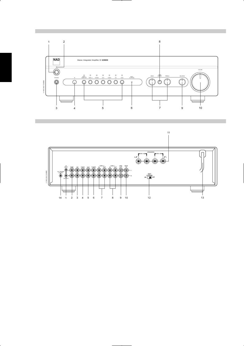
FRONT PANEL CONTROLS
REAR PANEL CONNECTIONS
NAD is a trademark of NAD Electronics International, a division of Lenbrook Industries Limited Copyright 2002, NAD Electronics International, a division of Lenbrook Industries Limited
4

NOTES ON INSTALLATION
Your NAD C320BEE should be placed on a firm, level surface. Avoid placing the unit in direct sunlight or near sources of heat and damp. Allow adequate ventilation. Do not place the unit on a soft surface like a carpet. Do not place it in an enclosed position such a bookcase or cabinet that may impede the air-flow through the ventilation slots. Make sure the unit is switched off before making any connections.
The RCA sockets on your NAD C320BEE are colour coded for convenience. Red and white are Right and Left audio respectively, and yellow for NAD Link.
Use high quality leads and sockets for optimum performance and reliability. Ensure that leads and sockets are not damaged in any way and all sockets are firmly pushed home.
For best performance, use quality speaker leads of 16 gauge (1.5mm) thickness or more. If the unit is not going to be used for some time, disconnect the plug from the AC socket.
Should water get into your NAD C320BEE, shut off the power to the unit and remove the plug from the AC socket. Have the unit inspected by a qualified service technician before attempting to use it again.
DO NOT REMOVE THE COVER, THERE ARE NO USERSERVICEABLE PARTS INSIDE.
Use a dry soft cloth to clean the unit. If necessary, lightly dampen the cloth with soapy water. Do not use solutions containing benzol or other volatile agents.
QUICK START
1Connect the speakers to the rear Speaker terminals and sources to the relevant rear input sockets.
2Plug in the AC power cord.
3Press the POWER button to turn the NAD C320BEE on.
4Press the required input selector.
FRONT PANEL CONTROLS
1Power - Pressing the Power switch turns the unit to standby state. Upon selecting any input at the front panel or the ON button at the remote, the C320BEE will choose the last selected as the active input. The LED over the power switch will change form amber, indicating standby state, to green when any input is selected. Pressing the POWER switch again will turn the amplifier off.
NOTE
The remote control handset supplied with the C320BEE is of a universal NAD type, designed to operate several NAD models. Some buttons on this handset are inoperative, as the functions aren’t supported by the C320BEE.
2Power/Standby/Protection LED - Upon switching the power on, the LED will light up red for a few seconds before the protection circuit is deactivated. The LED will then turn amber, and the amplifier is ready for normal operation. In cases of serious abuse of the amplifier, such as overheating, excessively low loudspeaker impedance, short circuit etc. the amplifier will engage its Protection circuitry, indicated by the LED turning from green to red, and the sound being muted. In such a case, turn the amplifier off, wait for it to cool down and/or check the speaker connections, making sure the overall loudspeaker impedance doesn’t go below 4 ohms. Once the cause for the protection circuitry to engage has been removed, press Power again to resume normal operation.
3Headphone socket - A 1/4” stereo jack socket is supplied for headphone listening and will work with conventional headphones of any impedance. Inserting a headphone jack into this socket automatically switches off the loudspeakers. The volume, tone and balance controls are operative for headphone listening. Use a suitable adapter to connect headphones with other types of sockets, such as 3.5mm stereo ‘personal stereo’ jack plugs.
NOTE
Make certain that the volume control is turned to minimum (fully anti-clockwise) before connecting or disconnecting headphones. Listening at high levels can damage your hearing.
4Infra-red remote control command receiver - The infrared sensor, located behind this circular window, receives commands from the remote control. There must be a clear line-of-sight path from the remote control to this window; if that path is obstructed, the remote control may not work.
NOTE
Direct sunlight or very bright ambient lighting may affect the operating range and angle for the remote control handset.
5Input selectors These buttons select the active input to the NAD C320BEE and the signal sent to the loudspeakers, the Tape outputs and the PRE OUT sockets. The buttons on the remote control handset duplicate these buttons, with the exception of the tuner input; see below. Green LEDs just above each button will indicate which input is currently selected.
DISC Selects a line-level source connected to the DISC sockets as the active input.
CD Selects the CD (or other line-level source) connected to the CD sockets as the active input.
VIDEO Selects the VCR (or stereo TV/Satellite/Cable receiver) connected to the VIDEO sockets as the active input.
AUX Selects a line-level source connected to the AUX sockets as the active input.
TUNER Selects the tuner (or other line-level source) connected to the Tuner sockets as the active input. The remote control handset has separate buttons for AM and FM; pressing either one will select the C320BEE’s tuner input.
TAPE 2 Selects Tape 2 as the active input.
TAPE 1 Monitor Selects the output from a tape recorder when playing back tapes or monitoring recordings being made through the Tape 1 sockets. Press the Tape 1 button once to select it and again to return to the normal input selection.
SVENSKA PORTUGUÊS ITALIANO ESPAÑOL NEDERLANDS DEUTSCH FRANÇAIS ENGLISH
5

SVENSKA PORTUGUÊS ITALIANO ESPAÑOL NEDERLANDS DEUTSCH FRANÇAIS ENGLISH
Tape 1 is a tape Monitor function which does not override the current input selection. For example, if the CD is the active input when TAPE 1 is selected, then the CD signal will continue to be selected and sent to both the TAPE 2, and TAPE 1 OUTPUT sockets, but it is the sound from recorder connected to Tape 1 that will be heard on the loudspeakers. Apart from the amber LED to indicate Tape 1 is engaged, the green LED for the active input will also stay lit.
NOTE
The remote control handset with the C320BEE supplied is of a universal NAD type, designed to operate several NAD models. Some buttons on this handset are inoperative as the functions aren’t supported by the C320BEE. The Video 2 and Video 3 input selector buttons on the remote control handset are inoperative in the case of the C320BEE.
6Soft clipping indicator - The green Soft Clipping LED shows that the Soft Clipping mode is engaged. Refer also to “Rear Panel Connections, Section 12 Soft Clipping” for more information.
7Tone controls - The NAD C320BEE is fitted with BASS and TREBLE tone controls to adjust the tonal balance of your system.
The 12 o’clock position is ‘flat’ with no boost or cut, and an indent indicates this position. Rotate the control clockwise to increase the amount of Bass or Treble. Rotate the control anti-clockwise to decrease the amount of Bass or Treble. The Tone controls do not affect recordings made using the Tape outputs but will affect the signal going to the Pre-amp output (Pre Out).
8Tone defeat - The TONE DEFEAT switch by-passes the tone control section of the NAD C320BEE. If the Tone Controls are not normally used and left in the 12 o’clock position, then it is advisable to switch out the Tone Control section altogether by using this switch. In the ‘out’ position, the Tone Control circuits are active, pushing the TONE DEFEAT switch ‘in’ bypasses the Tone Control section.
9Balance - The BALANCE control adjusts the relative levels of the left and right speakers. The 12 o’clock position provides equal level to the left and right channels. A detent indicates this position.
Rotating the control clockwise moves the balance towards the right. Rotating the control anti-clockwise moves the balance to the left. The BALANCE control does not affect recordings made using the Tape outputs but will affect the signal going to the Pre-amp output (Pre Out).
10Volume - The VOLUME control adjusts the overall loudness of the signals being fed to the loudspeakers. It is motor driven and can be adjusted from the remote control handset. The VOLUME control does not affect recordings made using the Tape outputs but will affect the signal going to the Pre-amp output (Pre Out).
On the remote control handset, press the MUTE button to temporarily switch off the sound to the speakers and headphones. Mute mode is indicated by the active input LED flashing. Press the MUTE button again to restore sound. Mute does not affect recordings made using the Tape outputs but will affect the signal going to the Pre-amp output (Pre Out).
REAR PANEL CONNECTIONS
1IR Input / output - This input is connected to the output of an IR (infrared) repeater (Xantech or similar), or the IR output of another component to allow control of the C320BEE from a remote location. Ask your dealer or custom installer for further details.
2Disc input - Input for additional line level input signals such as CD, Mini Disc player or the output signal from a step-up amplifier for a turntable. Use a twin RCA-to-RCA lead to connect the auxiliary unit’s left and right ‘Audio Outputs’ to this input.
3CD input - Input for a CD or other line-level signal source. Use a twin RCA-to-RCA lead to connect the CD player’s left and right ‘Audio Outputs’ to this input. The NAD C320BEE only accepts analogue signals from your CD player.
4Video input - Input for the audio signal from a stereo VCR (or stereo TV/Satellite/Cable receiver) or other line-level audio source. Using twin RCA-to-RCA leads, connect to the left and right ‘Audio Outputs’ of the unit to these inputs. Note: These are audio inputs only.
5AUX input - Input for additional line level input signals such as another CD player. Use a twin RCA-to-RCA lead to connect the auxiliary unit’s left and right ‘Audio Outputs’ to this input.
6Tuner input - Input for a tuner or other line-level signal source. Use a twin RCA-to-RCA lead to connect the tuner left and right ‘Audio Outputs’ to this input.
7Tape 2 In/Out - Connections for analogue recording and playback to an audio tape recorder of any type. Using twin RCA-to-RCA leads, connect to the left and right ‘Audio Output’ of the tape machine to the TAPE 2 IN sockets for playback and tape monitoring. Connect the left and right ‘Audio Input’ of the tape machine to the TAPE 2 OUT sockets for recording.
8Tape 1 In/Out - Connections for analogue recording and playback to an audio tape recorder of any type. Using twin RCA-to-RCA leads, connect to the left and right ‘Audio Output’ of the tape machine to the TAPE 1 IN sockets for playback and tape monitoring. Connect the left and right ‘Audio Input’ of the tape machine to the TAPE 1 OUT sockets for recording.
9Pre out - Connections to an external power amplifier or processor, such as a surround-sound decoder. In normal use these should be connected to the Main-In sockets (No. 10) with the links supplied. To connect your NAD C320BEE to external processor or amplifier sections first remove these links. Use a twin RCA-to-RCA lead to connect to the left and right ‘Audio Input’ of the Power amp or processor to the Pre Out sockets.
NOTE
The Pre-Out output signal will be affected by the NAD C320BEE’s volume and tone control settings, always turn the amplifier off before connecting or disconnecting anything from to Pre-Out and Main-In sockets.
6

10Main in - Connections to an external pre-amplifier or processor, such as a surround-sound decoder. In normal use these should be connected to the Pre-Out sockets (No. 9) with the links supplied. To connect your NAD C320BEE to external processor or pre-amplifier first remove these links. Use a twin RCA-to-RCA lead to connect to the left and right ‘Audio Output’ of the pre-amp or processor to the Main-In sockets.
NOTE
Always turn the amplifier off before connecting or disconnecting anything from to Pre-Out and Main-In sockets.
11 Speakers - Speaker terminals for speakers with an impedance of 4 ohms or more. Connect the right speaker to the terminals market ‘R +’ and ‘R-’ ensuring that the ‘R+’ is connected to the ‘+’ terminal on your loudspeaker and the ‘R-’ is connected to the loudspeaker’s ‘-’ terminal. Connect the terminals marked ‘L+’ and ‘L-’ to the left speaker in the same way.
Always use heavy duty (16 gauge; 1.5mm, or thicker) stranded wire to connect loudspeakers to your NAD C320BEE. The high-current binding post terminals can be used as a screw terminal for cables terminating in spade or pin sockets or for cables with bare wire ends.
BARE WIRES AND PIN CONNECTORS
Bare wires and pin sockets should be inserted into the hole in the shaft of the terminal. Unscrew the speaker terminal’s plastic bushing until the hole in the screw shaft is revealed. Insert the pin or bare cable end into the hole and secure the cable by tightening down the terminal’s bushing. Ensure bare wire from the speaker cables does not touch the back panel or another socket. Ensure that there is only 1/2” (1cm) of bare cable or pin and no loose strands of speakers wire.
12 Soft Clipping™ - When an amplifier is driven beyond its specified power output, a hard, distorted sound can be heard on very loud sounds. This is caused by the amplifier cutting off or ‘hard clipping’ the peaks of sound that was not designed to reproduce. The NAD Soft Clipping circuit gently limits the output of the system to minimise audible distortion if the amplifier is overdriven.
If your listening involves moderate power levels you may leave the Soft Clipping switch to Off. If you are likely to play at high levels, that could stretch the amplifier’s power capability, then switch Soft Clipping On.
The Soft Clipping™ LED on the front panel will illuminate when the amplifier is in Soft Clipping mode.
13 AC line cord - Plug the AC power cord into a live AC wall socket. Make sure all connections have been made before connecting to mains.
14 12V trigger output - The 12V TRIGGER OUTPUT is used for controlling external equipment that is equipped with a 12V trigger input. This output will be 12V when the C320BEE is on and 0V when the unit is either off or in standby. This output can drive a load up to 100ma at 12V.
TO MAKE A RECORDING
When any source is selected, its signal is also fed directly to any tape machine connected to the TAPE 2 or TAPE 1 OUTPUTS for recording.
TAPE TO TAPE COPYING
You can copy between two tape machines connected to your NAD C320BEE. Put the source tape in the recorder connected to Tape 2 and the blank tape into the recorder connected to Tape 1. By selecting TAPE 2 Input you can now record from Tape 2 to Tape 1 and monitor the signal coming from the original tape.
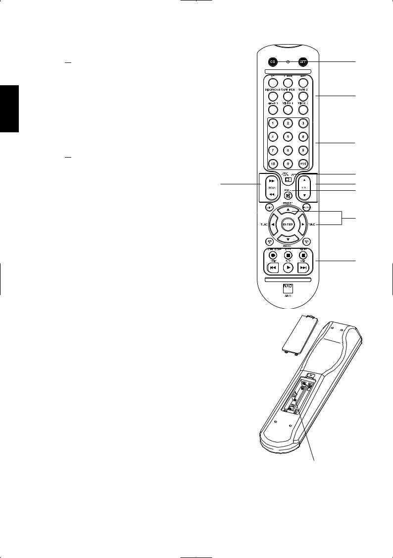
REMOTE CONTROL HANDSET
The Remote Control handset handles all the key functions of the NAD C720BEE and has additional controls to remotely operate NAD Cassette and CD machines. It will operate up to a distance of 16ft (5m). Alkaline batteries are recommended for maximum operating life. Two AAA (R 03) batteries should be fitted in the battery compartment at the back of the Remote Control handset. When replacing batteries, check that they have been put in the right way round, as indicated on the base of the battery compartment.
Please refer to previous sections of the manual for a full description of individual functions.
When a command from the remote control is received, the Standby/protection indicator will blink.
1 POWER ON & OFF - The NAD C320BEE remote has a separate On and Off button. This can be particularly useful to keep components within a system "insync": This way all components will switch to stand-by when Off is pressed or switch to operating mode when On is pressed, instead of some components switching On when the amplifier is switched to Stand-by. (Note that the other components have to be capable of responding to the separate On and Off commands as well). Press the ON button to switch the unit from Stand-by to the operating mode; The Stand-by indicator (Fig. 2; No. 2) will turn from amber, to red, then to green. Press the OFF button to switch the unit to the Stand-by mode: The Stand-by indicator will light up amber.
2 INPUTS - The input selector buttons perform the same functions as the buttons labelled the same on the front panel.
3 Numeric Keys - The numeric keys allow for direct input of tracks for CD-players, and direct channel/preset access for the tuner.
4 MASTER VOLUME - Press the MASTER VOLUME  or
or  buttons to respectively increase or decrease the loudness level. Release the button when the desired level is reached. The motorised Volume Control on the front panel will indicate the level set. The Master Volume buttons do not affect recordings made using the Tape outputs but will affect the signal going to the Pre-amp outputs.
5 MUTE - Press the MUTE Button to temporarily switch off the sound to the speakers and headphones. Mute mode is indicated by the MUTE icon in the VFD. Press MUTE again to restore sound. Mute does not affect recordings made using the Tape output but will affect the signal going to the Preamp outputs.
6 TUNER CONTROL - TUNE or
or  scans respectively higher or lower station frequencies for both AM and FM.
PRESET or
or  selects respectively higher or lower number station preset.
SVENSKA PORTUGUÊS ITALIANO ESPAÑOL NEDERLANDS DEUTSCH FRANÇAIS ENGLISH
7
SVENSKA PORTUGUÊS ITALIANO ESPAÑOL NEDERLANDS DEUTSCH FRANÇAIS ENGLISH
7 CD PLAYER CONTROL - (for use with NAD CD-Player) | | engages Pause
 engages Stop
 engages Play or toggles between Play and Pause or engages Track skip; Press once to respectively go to the next track or to return to start of current or previous track.

 engages reverse Scan and Skip


 engages forward Scan and Skip.
 engages CD drawer Open/Close; Press once to open the CD drawer then once again to close the CD drawer and start playback.
7 CASSETTE DECK CONTROL - (for use with single NAD Cassette Decks)
 engages Forward Play.
 Press to put cassette deck into record-pause, then press Play to start recording.
 Stops Play or Recording.

 engages Rewind.

 engages Fast Forward.
7
8 TAPE/TUNER-CD - The TAPE/TUNER - CD switch applies tape controls to the transport keys when in the TAPE/TUNER position, and applies CD controls to the transport keys when in the CD position.
9 DEV 1/DEV 2 - In some instances when one's audio system is without a tape deck, the CD transport keys may be set to operate in either position of the Tape/Tuner -CD switch (No.8).
The default setting for this remote control switch set to DEV 1. In this position, the Tape/Tuner -CD switch allows for both tape and CD control (No.7). If one sets this switch to DEV 2, then the transport keys will remain as CD control keys irregardless of the position of the Tap/Tuner -CD switch.
NOTES: The remote control handset supplied with the C320BEE is of a universal NAD type, designed to operate several NAD models. Some buttons on this handset are inoperative as the functions aren't supported by the C320BEE. The Video 2 and Video 3 input selector buttons (inside section No.2) on the remote control handset are inoperative in the case of the C320BEE.
Direct sunlight or very bright ambient lighting may affect the operating range and angle for the remote control handset.
1
2
3
8
4
5
6
7
DEV1
DEV2
9
8
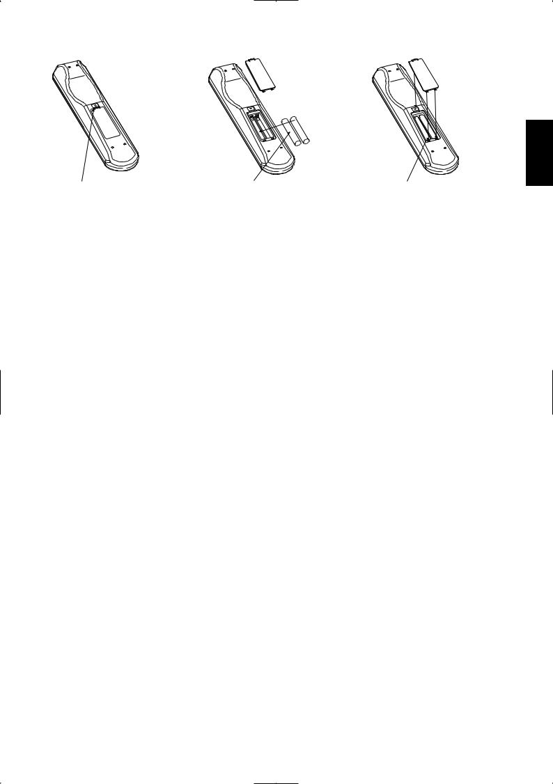
PRESS IN AND LIFT TAB TO REMOVE |
PLACE BATTERIES INTO OPENING. ENSURE |
REPLACE BATTERY COVER BY ALIGNING AND |
BATTERY COVER OUT FROM RECESS |
THE CORRECT POLARITY IS OBSERVED |
INSERTING THE TWO TABS INTO THE HOLES. |
|
|
PRESS BATTERY COVER INTO PLACE UNTIL IT |
|
|
'CLICKS' CLOSED |
|
TROUBLESHOOTING |
|
|
|
|
|
|
PROBLEM |
|
CAUSE |
|
SOLUTION |
|
|
|
|
|
|
|
|
NO SOUND |
• |
Power AC lead unplugged or power not |
• Check if AC lead is plugged in and power |
|||
|
|
|
switched on |
|
switched on |
|
|
|
|
|
|
||
|
|
• Tape 1 Monitor selected |
• De-select Tape 1 Monitor mode |
|||
|
|
|
|
|
|
|
|
|
• |
Mute on |
• |
Switch off Mute |
|
|
|
|
|
|
|
|
|
|
• Rear Pre-out/Main-in amp links not fitted |
• |
Fit links |
||
|
|
|
|
|
|
|
|
|
• |
Headphones inserted |
• |
Disconnect headphones |
|
|
|
|
|
|
|
|
NO SOUND ONE CHANNEL |
• |
Balance control not centered |
• |
Center Balance control |
||
|
|
|
|
|
||
|
|
• Speaker not properly connected or damaged |
• Check connections and speakers |
|||
|
|
|
|
|
||
|
|
• Input lead disconnected or damaged |
• Check leads and connections |
|||
|
|
|
|
|
|
|
WEAK BASS / DIFFUSE STEREO IMAGE |
• |
Speakers wired out of phase |
• Check connections to all speakers in the system |
|||
|
|
|
|
|
|
|
REMOTE CONTROL HANDSET |
• |
Batteries flat, or incorrectly inserted |
• Check or replace batteries |
|||
NOT WORKING |
|
|
|
|
|
|
|
|
|
|
|
|
|
|
|
• IR transmitter or receiver windows obstructed |
• |
Remove obstruction |
||
|
|
|
|
|
||
|
|
• IR receiver in direct sun or very bright ambient |
• Place unit away from direct sun, reduce amount |
|||
|
|
|
light |
|
of ambient light |
|
|
|
|
|
|
|
|
POWER/PROTECTION LED TURNS RED |
• |
Amplifier has overheated |
• Turn amplifier off, make sure ventilation slots on |
|||
DURING OPERATION |
|
|
|
top and bottom of amplifier are not blocked. |
||
|
|
|
|
|
After amplifier has cooled down, turn back on |
|
|
|
|
|
|
||
|
|
• Overall impedance of loudspeakers too low |
• Ensure the overall loudspeaker impedance is not |
|||
|
|
|
|
|
below 4 ohms |
|
|
|
|
|
|
|
|
SVENSKA PORTUGUÊS ITALIANO ESPAÑOL NEDERLANDS DEUTSCH FRANÇAIS ENGLISH
9

SVENSKA PORTUGUÊS ITALIANO ESPAÑOL NEDERLANDS DEUTSCH FRANÇAIS ENGLISH
SPECIFICATIONS |
|
|
|
|
|
|
|
PRE-AMP SECTION |
|
|
|
Line level inputs (Disc, CD, Video, Aux, Tuner, Tape1, Tape2) |
|
|
|
|
|
|
|
Input impedance (R and C) |
|
200kΩ + 320pF |
|
Input sensitivity (ref. rated power) |
|
|
220mV |
Maximum input signal |
|
|
6V |
Signal / Noise ratio A-weighted 1 |
|
|
93.0dB ref. 1W |
Signal / noise ratio pre-amp out, A-weighted |
|
|
106dB ref. 500mV |
Frequency response 20Hz - 20kHz |
|
|
<±0.1dB (Tone defeat on) |
|
|
|
<±0.5dB (Tone defeat off) |
THD + Noise, SMPTE IM |
|
|
< 0.01% at 5V out |
|
|
|
|
Line level outputs |
|
|
|
Output impedance |
|
Pre-out |
80Ω |
|
|
Tape |
Source Z + 1kΩ |
Maximum output level |
|
Pre-out |
>12V |
|
|
Tape |
>10V |
|
|
|
|
Tone controls |
|
|
|
Treble |
|
|
±5dB at 10kHz |
Bass |
|
|
±8dB at 100Hz |
|
|
|
|
Trigger out |
|
|
|
Input resistance |
|
|
>10kΩ |
Input voltage |
|
|
Minimum 5V |
Output resistance |
|
|
<30W |
Output current |
|
|
200mA |
Output voltage |
|
|
12V |
|
|
|
|
POWER AMP SECTION |
|
|
|
Continuous output power into 8Ω 2 |
|
|
50W (17dBW) |
Rated distortion (THD 20Hz - 20kHz) |
|
|
0.03% |
Clipping power (maximum continuous power per channel 4Ω and 8Ω) |
68W |
||
|
|
|
|
IHF Dynamic headroom |
8Ω |
+3.4dB |
|
|
|
4Ω |
+5.0dB |
IHF dynamic power (maximum short term power per |
channel) |
8Ω |
110W (20.4dBW) |
|
|
4Ω |
160W (22.0dBW) |
|
|
2Ω |
210W (23.2dBW) |
Damping factor (ref. 8Ω, 1kHz) |
|
|
>160 |
Input impedance (R & C) |
|
|
20kΩ + 470pF |
Input sensitivity (rated output into 8Ω) |
|
|
630mV |
Voltage gain |
|
|
29dB |
Frequency response 20Hz - 20kHz |
|
|
29dB |
Signal/noise ratio, A-weighted |
|
ref. 1W |
100dB |
|
|
ref. 50W |
117dB |
THD + Noise 3 |
|
|
<0.03% |
SMPTE IM 4 |
|
|
<0.01% |
IHF IM 5 |
|
|
<0.01% |
Headphone output impedance |
|
|
220Ω |
|
|
|
|
PHYSICAL SPECIFICATIONS |
|
|
|
Dimensions (W x H x D) |
|
|
435 x 100 x 290mm |
Net weight |
|
|
6.5kg (14.3lb) |
Shipping weight |
|
|
8kg (17.6lb) |
1 From CD input to speakers output, volume setting for 500mV in, 8Ω 1W out
2 Minimum power per chnnel, 20Hz - 20kHz, both channels driven with no more than rated distiortion.
3 Total harmonic distortion, 20Hz - 20kHz from 250mW to rated output
4 Intermodulation distortion, 60Hz - 7kHz, 4:1, from 250mW to rated output
5 CCIF IM distortion, 19 + 20kHz rated output
Dimensions are of unit’s cabinet without attached feet; add up to 18mm for total height.
Dimension depth excludes terminals, sockets, controls and buttons.
10
11
SVENSKA |
PORTUGUÊS |
ITALIANO |
ESPAÑOL |
NEDERLANDS |
DEUTSCH |
FRANÇAIS |
ENGLISH |
SVENSKA PORTUGUÊS ITALIANO ESPAÑOL NEDERLANDS DEUTSCH FRANÇAIS ENGLISH
CONSIGNES DE SÉCURITÉ IMPORTANTES
EXPLICATION DES SYMBOLES GRAPHIQUES
Le symbole de l'éclair avec une flèche à son extrémité, dans un triangle équilatéral, a pour but d'avertir l'utilisateur de la présence d'une "tension électrique dangereuse" à l'intérieur de l'enceinte de l'appareil, qui peut être suffisamment puissante pour constituer un risque de choc électrique pour les personnes.
Le point d'exclamation dans un triangle équilatéral a pour but d'avertir l'utilisateur que la documentation livrée avec l'appareil contient des instructions importantes concernant l'utilisation et l'entretien.
PRÉCAUTIONS
Lisez attentivement l'ensemble des Instructions d'Utilisation avant de faire fonctionner l'appareil. Conservez les Instructions d'Utilisation afin de pouvoir vous y référer à une date ultérieure. Tous les avertissements et toutes les mises en garde imprimés dans les Instructions d'Utilisation et sur l'appareil luimême doivent être respectés. Il en est de même pour les recommandations suivantes concernant la sécurité.
INSTALLATION
1Eau et Humidité - Cet appareil ne doit pas être utilisé à proximité de l'eau, par exemple près d'une baignoire, d'un lavabo, d'une piscine, etc ...
2Chaleur - N'utilisez pas cet appareil à proximité d'une source de chaleur comme une bouche de chauffage, une cuisinière ou tout autre appareil dégageant de la chaleur. L'appareil ne doit pas être mis en présence de températures inférieures à 5 °C ou supérieures à 35 °C.
3Support - Posez l'appareil sur une surface plane et horizontale.
4Aération - L'appareil doit être installé dans un endroit où l'air peut circuler librement autour, afin de bien évacuer la chaleur dégagée. Prévoyez un dégagement de 10 cm derrière et au dessus de l'appareil et de 5 cm de chaque côté. - Ne posez pas l'appareil sur un lit, un tapis ou une surface semblable, car
cela boucherait les ouvertures d'aération sur la face inférieure. - N'installez pas l'appareil dans une bibliothèque fermée ou dans un rack hermétique, car la ventilation de l'appareil ne serait pas assurée correctement.
5Pénétration de corps étrangers ou de liquides - Veillez à ce qu'aucun objet ni aucun liquide ne pénètre à l'intérieur de l'appareil à travers les ouvertures d'aération.
6Chariots et supports - Si vous placez ou installez l'appareil sur un support ou sur un chariot, les déplacements doivent être effectués en faisant très attention. Les arrêts brusques, les efforts excessifs ou les sols accidentés risqueraient de renverser le chariot et l'appareil.
7Condensation - De l'humidité peut se déposer sur la lentille de lecture des CD lorsque :
•Vous déplacez l'appareil d'un endroit frais à un endroit plus chaud.
•Vous venez d'allumer le chauffage.
•Vous utilisez l'appareil dans une pièce très humide.
•L'appareil est refroidi par un climatiseur.
Si de la condensation s'est formée à l'intérieur de cet appareil, cela peut en perturber le fonctionnement. Si cela arrive, attendez quelques heures puis essayez à nouveau.
8Fixation au mur ou au plafond - L'appareil ne doit pas être fixé au mur ou au plafond, à moins que cela ne soit prévu dans les Instructions de l'Utilisateur.
UN MOT SUR LA PROTECTION DE L'ENVIRONNEMENT
Au terme de sa durée de vie, ce produit ne doit pas être jeté avec les ordures ménagères ordinaires, mais retourné à un point de collecte pour recyclage des composants électriques et électroniques. Le symbole sur le produit, sur le manuel d'installation et sur l'emballage attire l'attention sur ce point.
Les matériaux peuvent être réutilisés en conformité avec leur marquage. A travers la réutilisation et le recyclage des matériaux bruts, ou toutes autres formes de recyclage des produits anciens, vous contribuez de manière importante à protéger notre environnement.
Votre municipalité peut vous indiquer où se trouve le point de collecte le plus proche.
ATTENTION DANGER. POUR ÉVITER TOUT RISQUE D'INCENDIE OU DE CHOC ÉLECTRIQUE, N'EXPOSEZ JAMAIS CET APPAREIL A LA PLUIE OU A L'HUMIDITÉ.
Ce produit a été fabriqué de manière à être conforme aux exigences concernant les interférence radio des
DIRECTIVES CEE 89/68/EEC et 73/23/EEC.
12
CONSIGNES DE SÉCURITÉ
ALIMENTATION ÉLECTRIQUE
1Sources d'alimentation - Ce produit doit obligatoirement être alimenté par une source du type indiqué dans les Instructions d'Utilisation et sur l'appareil lui-même.
2Polarité - Pour des raisons de sécurité, il se peut que cet appareil soit équipé d'une prise secteur alternatif avec système de détrompage interdisant tout branchement dans le "mauvais sens". Si la fiche n'entre pas (ou pas complètement) dans la prise murale, essayez de la brancher dans l'autre sens. Si elle n'entre toujours pas, appelez un électricien qualifié pour faire réparer ou remplacer votre prise murale. Afin de ne pas détériorer le dispositif de sécurité de la prise détrompée, n'essayez pas de la brancher de force dans la prise murale.
3Cordon d'alimentation secteur - Lorsque vous débranchez le cordon d'alimentation secteur, tirez sur la fiche secteur et non sur le cordon.
•Ne touchez jamais la fiche ou la prise secteur si vous avez les mains mouillées, car vous risqueriez de subir un choc électrique ou de provoquer un incendie.
•Les câbles d'alimentation ne doivent pas passer dans des endroits où ils risquent d'être piétinés ou pincés ou tordus excessivement. Faites particulièrement attention à ces détails pour ce qui concerne le câble entre l'appareil et la prise murale.
•Évitez de surcharger les prises de secteur murales et/ou les rallonges, car cela risquerait d'entraîner un incendie ou de provoquer un choc électrique.
4Rallonge électrique - Afin de contribuer à éviter les chocs électriques, ne branchez jamais une fiche secteur détrompée sur une rallonge électrique, une embase ou une quelconque autre source de courant si la fiche ne peut pas être complètement enfoncée dans la prise : les broches de la fiche doivent être inaccessibles.
5Lorsque l'appareil n'est pas utilisé - Débranchez le cordon secteur de la prise murale si l'appareil ne va pas être utilisé pendant plusieurs mois. Lorsque le cordon reste branché, un courant faible est débité par l'appareil, même s'il est hors tension.
ATTENTION
En cas de réglage ou de modification dont la conformité n'aura pas été expressément approuvée par le fabricant, le droit de l'utilisateur de faire fonctionner l'appareil risque d'être retiré.
ENTRETIEN
Nettoyez cet appareil conformément aux recommandations données dans les Instructions de l'Utilisateur.
DÉTÉRIORATIONS NÉCESSITANT UNE INTERVENTION
Dans les cas suivants, faites réparer l'appareil par un technicien de service après vente qualifié :
•Détérioration de la fiche d'alimentation secteur.
•Pénétration de corps étrangers ou de liquides à l'intérieur de l'appareil.
•L'appareil a été exposé à la pluie ou à l'humidité - L'appareil semble ne pas fonctionner correctement.
•Les performances de l'appareil se sont sensiblement détériorées.
•L'appareil a subi une chute, ou le boîtier a été endommagé.
NE TENTEZ AUCUNE RÉPARATION VOUS-MÊME.
INFORMATIONS PARTICULIÈRES
Pour simplifier vos démarches, notez ci-dessous le numéro de modèle et le numéro de série de votre appareil (vous les trouverez à l'arrière de l'appareil lui-même). Veuillez les rappeler lorsque vous contacterez votre revendeur, en cas de problème.
N° de Modèle :
N° de Série :
SVENSKA PORTUGUÊS ITALIANO ESPAÑOL NEDERLANDS DEUTSCH FRANÇAIS ENGLISH
13

SVENSKA PORTUGUÊS ITALIANO ESPAÑOL NEDERLANDS DEUTSCH FRANÇAIS ENGLISH
NOTES CONCERNANT L’INSTALLATION
Posez votre NAD C320BEE sur une surface, stable, plane et horizontale. Évitez les rayons directs du soleil et les sources de chaleur et d’humidité. Assurez une ventilation adéquate. Ne posez pas cet appareil sur une surface molle (moquette, par exemple). Ne le placez pas dans un endroit confiné (sur une étagère de bibliothèque ou derrière des portes vitrées), où le flux d’air à travers les ouïes de ventilation risque d’être entravé. Vérifiez que l’appareil est mis hors tension avant de réaliser des connexions quelconques.
Pour vous faciliter la tâche, les prises RCA de votre NAD C320BEE sont codées couleur. Rouge pour l’audio droite, blanc pour l’audio gauche. N’utilisez que des câbles et des connecteurs de très bonne qualité de manière à obtenir un branchement dont la fiabilité est parfaite et les performances optimales. Vérifiez que les câbles et les connecteurs ne présentent aucune détérioration, et que tous les connecteurs sont bien enfoncés jusqu’en butée.
Pour obtenir les meilleures performances, utilisez des câbles de hautparleurs d’une épaisseur égale ou supérieure au calibre 16 (1,5 mm) ou plus. Si l’appareil doit rester inutilisé pendant un certain temps, débranchez le cordon d’alimentation de la prise de secteur murale.
Si de l’eau pénètre à l’intérieur de votre NAD C320BEE, coupez l’alimentation de l’appareil et retirez la fiche de la prise secteur. Faites contrôler l’appareil par un technicien de service après-vente qualifié, avant toute tentative de remise en service.
NE RETIREZ PAS LE COUVERCLE, AUCUNE PIÈCE REPÉRABLE PAR L’UTILISATEUR NE SE TROUVE A L’INTÉRIEUR.
Utilisez un chiffon doux sec et propre pour nettoyer l’appareil. Si nécessaire, humectez le chiffon avec un peu d’eau savonneuse. N’utilisez jamais de solution contenant du benzol ou un quelconque autre agent volatile.
MISE EN MARCHE RAPIDE
1Branchez les haut-parleurs sur les prises “Haut-parleur” [Speaker] à l’arrière et brancher les sources aux prises d’entrée appropriées à l’arrière.
2Branchez le cordon d’alimentation secteur.
3Appuyez sur le bouton-poussoir marche/arrêt [POWER] pour mettre le NAD C320BEE sous tension.
4Appuyez sur le sélecteur d’entrée requis.
COMMANDES SUR LA FACE PARLANTE
1Alimentation [Power] - Appuyez sur le bouton d’Alimentation pour mettre l’appareil en mode veille (La LED au dessus du bouton d’Alimentation passe du vert à l’orange). L’appareil se remet en mode Marche lors de toute sélection d’une entrée quelconque sur la face parlante, ou de toute impulsion sur le bouton MARCHE [ON] de la télécommande ; dans ce dernier cas, le C320BEE choisira la dernière entrée sélectionnée comme entrée active. La LED au dessus du bouton d’Alimentation passe de l’orange (état de veille) au vert (état de marche) lorsque vous sélectionnez une entrée. Si vous appuyez à nouveau sur le bouton d’Alimentation [Power], l’amplificateur s’éteint.
NOTA
La télécommande livrée avec le C320BEE est de type universel NAD et est conçue pour commander plusieurs modèles NAD. Certains boutons de ce combiné ne fonctionnent pas car les fonctions concernées ne sont pas supportées par le C320BEE.
2LED Alimentation / Veille / Protection [Power / Standby / Protection] - Lorsque vous mettez l’appareil sous tension, la LED s’allume en orange (état de veille). Lorsque vous appuyez sur l’un des boutons de sélection d’entrée, la LED s’allume momentanément en rouge puis passe au vert (état de MARCHE). En cas d’importante surcharge de l’amplificateur, comme par exemple l’utilisation d’un haut-parleur d’impédance très faible, de court-circuit, etc ..., les circuits de protection de l’amplificateur entrent en jeu ; cet état est indiqué par le passage au rouge du LED, et par la coupure du son. Dans un cas comme celui-ci, mettez l’amplificateur hors tension, attendez qu’il refroidisse et vérifiez le branchement des hautparleurs, et vérifiez que l’impédance globale des haut-parleurs ne passe pas en dessous de 4 ohms. Une fois que vous aurez éliminé la cause du problème, appuyez à nouveau sur le bouton d’Alimentation [Power] pour reprendre le fonctionnement normal.
3Casque - Une prise stéréo pour fiche à jack de 1/4” est prévue pour l’écoute avec casque et convient aux casques conventionnels à impédance quelconque. Le fait de brancher la fiche jack d’un casque dans cette prise coupe automatiquement le son des haut-parleurs. Les commandes de volume sonore, de tonalité et de balance agissent aussi sur l’écoute sur casque. Utilisez un adaptateur approprié pour brancher des casques équipés d’un autre type de connecteur, tel qu’un jack stéréophonique de 3,5 mm de type “baladeur stéréo”.
NOTA
Vérifiez que la commande de volume sonore est au minimum (butée anti-horaire) avant de brancher ou de débrancher le casque. L’écoute à des niveaux sonores élevés peut entraîner des dommages auditifs permanents.
4 Récepteur infrarouge de télécommandes - Le capteur infrarouge, situé derrière cette fenêtre circulaire, reçoit les commandes de la télécommande. L’espace entre la télécommande et le récepteur doit être dégagé de tout obstacle, sinon la télécommande peut refuser de fonctionner.
NOTA
Les rayons de soleil directs ou un éclairage d’ambiance très lumineux peuvent avoir une incidence sur la plage et l’angle de fonctionnement de la télécommande.
5Selecteurs d’entree [Input Selectors] - Ces boutons permettent de sélectionner l’entrée active du NAD C320BEE ainsi que le signal envoyé aux haut-parleurs, aux sorties Magnétophone et aux prises PRE OUT. Les boutons sur la télécommande sont identiques à ces boutons, à l’exception de l’entrée tuner; voir ci-dessous. Une LED verte, à l’aplomb de chaque bouton, indique l’entrée active.
DISC [DISQUE] Sélectionne, comme entrée active, une source de niveau ligne branchée aux prises disque [DISC].
CD Sélectionne, comme entrée active, le lecteur CD (ou une source de niveau ligne) branchée aux prises CD.
VIDEO Sélectionne, comme entrée active, le magnétoscope (ou un téléviseur stéréo/décodeur satellite/récepteur de télédistribution) connecté aux prises VIDEO.
AUX Sélectionne, comme entrée active, une source de niveau ligne branchée aux prises AUX.
TUNER Sélectionne, comme entrée active, le tuner (ou une source de niveau ligne) branché aux prises Tuner. Le combiné de télécommande est pourvu de boutons distincts AM et FM ; une impulsion sur l’un ou l’autre sélectionnera l’entrée Tuner du C 320BEE.
MAGNÉTOPHONE 2 [TAPE 2] Sélectionne “Magnétophone 2” [Tape 2] comme l’entrée active.
14

TAPE 1 Monitor Sélectionne la sortie d’un magnétophone lors de la lecture de cassettes ou du suivi d’enregistrements à partir des prises “Magnétophone 1” [Tape 1]. Appuyez une fois sur le bouton “Magnétophone 1” [Tape 1] pour l’activer et une deuxième fois pour rétablir la sélection d’entrée normale.
“Magnétophone 1” [Tape 1] est une fonction de suivi magnétophone qui n’annule pas la sélection d’entrée en cours. Par exemple, si le CD est l’entrée active lorsque TAPE 1 est sélectionné, le signal CD continue d’être sélectionné et est envoyé aussi bien aux prises de sortie TAPE 2 et TAPE 1, mais c’est le son du magnétophone relié à TAPE 1 qui sera entendu sur les haut-parleurs. En plus du voyant orange indiquant le fonctionnement du Magnétophone 1, le voyant verte de l’entrée active restera allumé il aussi.
NOTA
La télécommande livrée avec le C320BEE est de type universel NAD et est conçue pour commander plusieurs modèles NAD. Certains boutons de ce combiné ne fonctionnent pas car les fonctions concernées ne sont pas supportées par le C320BEE. Les boutons de sélection d’entrée Vidéo 2 et Vidéo 3 sur la télécommande ne fonctionnent pas dans le cas du C 320BEE.
6Indicateur d’Écrêtage Doux - L’indicateur vert d’Écrêtage Doux indique que le mode d’Écrêtage Doux [Soft Clipping] est actif. Reportez-vous aussi au chapitre “Branchements sur le panneau arrière”, section 12 “Écrêtage Doux” pour de plus amples informations.
7Commandes de Tonalité - Le NAD C320BEE est équipé de commandes de GRAVES [BASS] ET d’AIGUS [TREBLE], qui permettent de régler la tonalité globale de votre chaîne. La position médiane (12 heures) correspond à une courbe plate, sans amplification ni atténuation; un léger déclic peut être ressenti dans le mouvement du bouton à cet endroit. Tournez le bouton en sens horaire pour amplifier les Graves ou les Aigus. Tournez le bouton en sens antihoraire pour atténuer les Graves ou les Aigus. Les commandes de Tonalité n’affectent pas les enregistrements faits au moyen des Sorties “Magnétophone” [TAPE] mais agissent toutefois sur le signal allant vers la “Sortie de Préamplification” [Pre Out].
8Tonalité Neutre [Tone defeat] - L’interrupteur de TONALITÉ NEUTRE [TONE DEFEAT] contourne la section de commande de la tonalité du NAD C320BEE. Si vous n’utilisez pas les commandes de tonalité, c’est à dire si elles restent toujours en position médiane (12 heures), il est conseillé de mettre les dispositifs de réglage de la tonalité complètement hors circuit grâce à ce bouton-interrupteur. Si le bouton n’est pas enfoncé, les circuits de tonalité sont actifs; le fait d’enfoncer le bouton “TONALITÉ NEUTRE” [TONE DEFEAT] contourne les circuits de réglage de la tonalité.
9Balance - La commande de BALANCE règle les niveaux relatifs des haut-parleurs gauche et droit. La position médiane (12 heures) assure un niveau égal pour les voies gauche et droite. Un léger déclic peut être ressenti dans le mouvement du bouton à cet endroit. En tournant le bouton en sens horaire, vous déportez l’équilibre vers la droite. En tournant le bouton en sens anti-horaire, vous déportez l’équilibre vers la gauche. La commande de BALANCE n’affecte pas les enregistrements faits au moyen des Sorties “Magnétophone” [TAPE] mais agit toutefois sur le signal allant vers la “Sortie de Préamplification” [Pre Out].
10Volume - La commande de VOLUME sonore règle le volume global des signaux envoyés aux haut-parleurs. Elle est motorisée et peut être réglée depuis la télécommande. La commande de VOLUME n’affecte pas les enregistrements faits au moyen des Sorties “Magnétophone” [TAPE] mais agit toutefois sur le signal allant vers la “Sortie de préamplification” [Pre Out]. Sur la télécommande, appuyez sur le bouton “Silencieux” [MUTE] pour couper provisoirement le son des haut-parleurs et du casque. Le mode Silencieux est indiqué par le clignotement du voyant de l’entrée active. Réappuyez sur le bouton Silencieux [MUTE] pour remettre le son. La commande Mute n’affecte pas les enregistrements faits au moyen des Sorties “Magnétophone” [TAPE] mais agit toutefois sur le signal allant vers la “Sortie de Préamplification” [Pre Out].
LIAISONS DE LA FACE ARRIÈRE
1Entrée / Sortie IR - Cette entrée est reliée à la sortie d’un relais IR (infrarouge) (Xantech ou similaire), ou à la sortie IR d’un autre élément permettant de commander le C320BEE depuis un endroit éloigné. Demandez à votre revendeur ou à votre installateur de vous fournir de plus amples informations.
2Entrée Disc - Entrée pour les signaux d’entrée supplémentaires de niveau ligne, tels qu’un lecteur CD, un lecteur Mini-Disc ou le signal de sortie provenant d’un amplificateur de rehausseur pour tournedisques. Utiliser un câble jumelé RCA vers RCA pour relier les connecteurs de “Sortie Audio” [Audio Outputs] gauche et droit de l’appareil audio auxiliaire à cette entrée.
3Entrée CD - Entrée pour un lecteur CD ou pour toute autre source de signal de niveau ligne. Utilisez un câble jumelé RCA vers RCA pour relier les connecteurs de sortie audio gauche et droit du lecteur CD à cette entrée. Le NAD C320BEE n’accepte que les signaux analogiques de votre lecteur CD.
4Entrée Vidéo input - Entrée pour le signal audio provenant d’un magnétoscope stéréo (ou TV stéréo / Satellite / Récepteur de télédistribution) ou d’une autre source audio de niveau ligne. En utilisant les câbles jumelés RCA vers RCA, reliez les connecteurs de “Sortie Audio” gauche et droit de l’appareil à ces entrées. Nota : Il s’agit d’entrées audio uniquement.
5Entrée AUX - Entrée pour d’autres signaux de niveau ligne, comme un deuxième lecteur CD par exemple. Utilisez un câble jumelé RCA vers RCA pour relier les connecteurs de “Sortie Audio” [Audio Outputs] gauche et droit de l’appareil audio auxiliaire à cette entrée.
6Entrée Tuner - Entrée pour un tuner ou pour toute autre source de signal de niveau ligne. Utilisez un câble jumelé RCA vers RCA pour relier les connecteurs de “Sortie Audio” gauche et droit de l’appareil à cette entrée.
7Entrée / Sortie Magnétophone 2 [Tape 2] - Branchements pour enregistrement et lecture analogiques sur un magnétophone audio de type quelconque. En utilisant les câbles jumelés RCA vers RCA, reliez les connecteurs de “Sortie Audio” gauche et droit du magnétophone aux prises d’ENTRÉE MAGNÉTOPHONE 2 [TAPE 1 IN] pour la lecture et le contrôle d’enregistrement des bandes. Reliez les connecteurs d’Entrée Audio gauche et droit du magnétophone aux prises de SORTIE MAGNÉTOPHONE 2 [TAPE 1 OUT] pour l’enregistrement des bandes.
SVENSKA PORTUGUÊS ITALIANO ESPAÑOL NEDERLANDS DEUTSCH FRANÇAIS ENGLISH
15

SVENSKA PORTUGUÊS ITALIANO ESPAÑOL NEDERLANDS DEUTSCH FRANÇAIS ENGLISH
8Entrée / Sortie Magnétophone 1 [Tape 1] - Branchements pour enregistrement et lecture analogiques sur un magnétophone audio de type quelconque. En utilisant les câbles jumelés RCA vers RCA, reliez les connecteurs de “Sortie Audio” gauche et droit du magnétophone aux prises d’ENTRÉE MAGNÉTOPHONE 1 [TAPE 1 IN] pour la lecture et le contrôle d’enregistrement des bandes. Reliez les connecteurs d’Entrée Audio gauche et droit du magnétophone aux prises de SORTIE MAGNÉTOPHONE 1 [TAPE 1 OUT] pour l’enregistrement des bandes.
9Sortie Préamplificateur [Pre out] - Branchements à un amplificateur de puissance externe ou à un processeur externe, tel qu’un décodeur de sonorisation enveloppante. Pour une utilisation normale, ceux-ci doivent être branchés sur les prises [Main-In] (N° 10) avec les liaisons prévues. Pour brancher votre NAD C320BEE à des modules processeurs ou d’amplificateur externes, il sera nécessaire d’enlever ces liaisons d’abord. Utilisez un câble jumelé RCA vers RCA pour brancher le connecteur d’Entrée Audio [Audio-Input] gauche et droit de l’amplificateur de puissance ou processeur aux prises de Sortie Préampli [Pre-Out].
NOTA
Le signal de sortie Préamplificateur [Pre-Out] sera affecté par les réglages de volume et de tonalité du NAD C320BEE ; mettez toujours l’amplificateur hors tension avant de brancher ou de débrancher quoique ce soit au niveau des prises sortie Préamplificateur [Pre-Out] ou d’Entrée Principale [Main-In].
10 Entrée Principale [Main in] - Branchements à un amplificateur de puissance externe ou un processeur externe, tel qu’un décodeur de sonorisation enveloppante. Pour une utilisation normale, ceux-ci doivent être branchés sur les prises [Pre-Out] (N° 9) avec les liaisons prévues. Pour brancher votre NAD C320BEE à une processeurs ou un préamplificateur externe, il sera nécessaire d’enlever ces liaisons d’abord. Utiliser un câble jumelé RCA vers RCA pour brancher le connecteur de Sortie Audio [Audio-Output] gauche et droit du préamplificateur ou processeur aux prises Main-In.
NOTA
Mettez toujours l’amplificateur hors tension avant de brancher ou de débrancher quelconque ce soit des prises Pre-Out et Main-In.
11 Haut-parleurs [Speakers] - Connecteurs de haut-parleurs, pour haut-parleurs ayant une impédance de 4 ohms ou plus. Branchez le haut-parleur droit sur les bornes repérées “R+” et “R-”, en vous assurant que le “R+” soit relié à la borne “+” de votre haut-parleur et que “R-” soit relié à la borne “-” de votre haut-parleur. Branchez les bornes repérées “L+” et “L-” au haut-parleur gauche en procédant de la même manière.
N’utilisez que du fil torsadé haute puissance (calibre 16 ; 1,5 mm ou plus) pour brancher les haut-parleurs à votre NAD C320BEE. Vous pouvez utiliser les bornes pour courants élevés comme bornes à visser pour les câbles comportant des cosses plates, des broches ou des fils nus.
FILS NUS ET BORNES A BROCHES
Les fils nus et les broches s’insèrent dans le trou diamétral percé dans la tige de la borne. Desserrez la bague en plastique de la borne de hautparleur jusqu’à ce que le trou axial dans la tige soit visible. Insérez la broche ou le fil nu dans le trou, puis fixez le câble en vissant la bague de la borne. Veillez à ce qu’aucun fil nu des câbles des haut-parleurs ne touche le panneau arrière ou une autre prise. Veillez à ce qu’il n’y ait que 1 cm (1/2”) de fil nu ou de broche et qu’il n’y ait aucun brin libre sur les fils des haut-parleurs.
12 ECRETAGE [SOFT CLIPPING] - Lorsqu’un amplificateur est poussé au-delà de sa puissance de sortie spécifiée, on entend un son dur et déformé lors des passages à sonorité forte. Cela provient du fait que l’amplificateur coupe ou “écrête de façon dure” les pointes sonores pour lesquelles sa conception ne permet pas la reproduction. Le circuit d’écrêtage doux, de NAD, limite en
douceur la forme d’onde à la sortie, pour minimiser la distorsion audible lorsque l’amplificateur est poussé au-delà de ses limites. Si votre écoute comporte des niveaux modérés de puissance, l’Écrêtage Doux peut être laissé sur ARRÊT [OFF]. Si, par contre, vous pensez passer de la musique à des niveaux très élevés, susceptibles de dépasser la capacité de puissance de l’amplificateur, nous préconisons de mettre l’Écrêtage Doux sur MARCHE [ON]. L’indicateur d’Écrêtage Doux sur la face parlante s’allume lorsque l’amplificateur est en mode Écrêtage Doux.
13 Câble d’alimentation secteur - Branchez ce cordon à une prise murale secteur. Veillez à ce que tous les branchements aient été faits avant de brancher le cordon au secteur.
14 Sortie Asservissement 12 V [12V trigger] - La SORTIE ASSERVISSEMENT 12 V [12V TRIGGER OUTPUT] permet de commander des appareils externes équipés d’une entrée d’asservissement 12 V. Cette sortie est au potentiel 12 V lorsque le C320BEE est en marche, ou au potentiel 0 V lorsque l’appareil est éteint ou en mode veille. Cette sortie est capable de piloter une charge pouvant atteindre 100 ma à 12V.
ENREGISTREMENT
Lorsqu’une source est sélectionnée, son signal est aussi envoyé directement à un quelconque magnétophone relié aux SORTIES “MAGNÉTOPHONE 2” ou “MAGNÉTOPHONE 1” [TAPE 2 ou TAPE 1] pour l’enregistrement.
“COPIER ENTRE CASSETTES” [TAPE TO TAPE]
Il est possible de réaliser des copies entre deux magnétophones connectés à votre NAD C320BEE. Mettez la bande source sur le magnétophone connecté à “Magnétophone 2” [Tape 2] et la bande vierge sur le magnétophone connecté à “Magnétophone 1” [Tape 1]. En sélectionnant l’Entrée “MAGNÉTOPHONE 2” [TAPE 2], il est possible d’enregistrer de “Magnétophone 2” à “Magnétophone 1”, et de contrôler le signal en provenance de la bande d’origine.
COMBINÉ DE TÉLÉCOMMANDE
La Télécommande reproduit toutes les fonctions clés du NAD C320BEE, et comporte aussi des commandes supplémentaires permettant de télécommander les Magnétophones à cassette et les Lecteurs de CD NAD. Elle fonctionne depuis une distance pouvant aller jusqu'à 5 mètres. Il est conseillé d'utiliser des piles alcalines pour une longévité maximale. Deux piles de type AAA (R 03) doivent être insérées dans le compartiment des piles à l'arrière du combiné Télécommande. Lors du remplacement des piles, assurez-vous de leur bonne orientation conformément au dessin dans le fond du compartiment des piles.
Reportez-vous aux sections précédentes du manuel pour des descriptions détaillées des différentes fonctions.
Lors de la réception d'une commande en provenance du combiné de télécommande, la lampe témoin "Veille / Protection" [Standby/Protection] clignote.
1 MARCHE / ARRÊT ALIMENTATION La télécommande du NAD C320BEE est dotée de touches Marche [On] et Arrêt [Off] distincts. Ceci est particulièrement utile pour maintenir la synchronisation des
16

appareils constituant la chaîne : De cette manière, tous les appareils passeront en mode Veille lorsque vous appuierez sur "Arrêt" [Off], ou passeront en mode Marche lorsque vous appuierez sur "On" [Marche], plutôt que de se mettre en Marche lorsque vous mettrez l'amplificateur en mode Veille. (A noter que les autres appareils doivent eux aussi être capables de répondre à des commandes de Marche / Arrêt distinctes). Appuyez sur la touche "Marche" [ON] pour faire passer l'appareil du mode Veille au mode de fonctionnement ; la lampe témoin Veille [Stand-by] (Fig. 2 ; N° 2) passera de l'orange au rouge, puis au vert. Appuyez sur la touche OFF pour mettre l'appareil en mode Veille : La lampe témoin de Veille passera à l'orange.
2 ENTRÉES Les touches de sélection des entrées ont les mêmes fonctions que les boutons repérés de façon identique sur la face parlante.
3 Touches numériquesLes touches numériques permettent d'entrer directement les numéros de piste pour les lecteurs de CD, et permettent d'accéder directement aux chaînes / stations présélectionnées (ou "presets") pour le tuner.
4 VOLUME GÉNÉRAL Appuyez sur les touches  ou
ou  du VOLUME GÉNÉRAL [MASTER VOLUME] pour augmenter ou diminuer le volume sonore, respectivement. Relâchez la touche dès que le niveau sonore souhaité a été atteint. La Commande de Volume motorisée sur la face parlante indiquera le niveau réglé. Les touches de Volume Global n'affectent pas les enregistrements faits au moyen des Sorties "Magnétophone" [Tape] mais agissent toutefois sur le signal allant vers les Sorties de préamplification [Preamp].
5 MUET [MUTE] Appuyez sur la touche MUET [MUTE] pour couper provisoirement l'émission du son vers les haut-parleurs et le casque. Le mode Muet est indiqué par l'icône MUET [MUTE] sur l'Affichage Vide-Fluorescent [VFD]. Réappuyez sur MUET [MUTE] pour rétablir le son. La commande Muet n'affecte pas les enregistrements faits au moyen de la Sortie "Magnétophone" [TAPE] mais agit toutefois sur le signal allant vers les sorties de Préamplification [Preamp].
6 COMMANDE DE TUNER Les touches d'ACCORDAGE  ou
ou  [TUNE
[TUNE  ou
ou  ] permettent de balayer les stations en remontant ou en descendant, respectivement, les bandes AM et FM. Les touches de PRÉSÉLECTION
  ou
ou  [PRESET
  or
or  ] sélectionnent le numéro de station présélectionnée (ou "preset") suivant ou précédent, respectivement.
7 COMMANDE LECTEUR CD [CD PLAYER] (à utiliser avec un lecteur de CD NAD)
La touche | | met l'appareil en mode Pause
La touche |
|
met l'appareil en mode Arrêt [Stop] |
||||
La touche |
active le mode Lecture [Play] ou permute entre les |
|||||
modes Lecture et Pause, ou active le mode Saut de Piste [Track Skip]; |
||||||
appuyez une fois sur cette touche soit pour sauter à la piste suivante, |
||||||
soit pour retourner au début de la piste en cours ou précédente. |
||||||
Les touches |
et |
|
|
activent les modes de balayage rapide en |
||
|
||||||
|
||||||
arrière et de saut en arrière. |
||||||
Les touches |
et |
|
activent les modes de balayage rapide en |
|||
|
||||||
|
||||||
avant et de saut en avant. |
|
|||||
La touche |
provoque l'Ouverture / Fermeture du plateau de CD ; |
|||||
appuyez une fois pour ouvrir le plateau de CD et une deuxième fois pour refermer le tiroir et commencer la lecture.
7 COMMANDES DE LA PLATINE A CASSETTES (à utiliser avec les platines à cassettes simples NAD)
La touche  active la Lecture en Avant.
 : Appuyez sur cette touche pour mettre la platine à cassettes en mode enregistrement-pause, puis appuyez sur Lecture [Play] pour
commencer l'enregistrement.
La touche  arrête la Lecture" ou l'Enregistrement.
Les touches 
 et
et  activent le Rembobinage Rapide [Rewind] Les touches
  et
et 
 activent l'Avance Rapide [Fast Forward].
8 MAGNÉTO/TUNER - CD [TAPE/TUNER - CD] Lorsque le sélecteur MAGNÉTO/TUNER - CD [TAPE/TUNER - CD] est en position MAGNÉTO/TUNER [TAPE/TUNER], les touches de défilement envoient des commandes de magnétophone ; lorsqu'il est en position CD, ces mêmes touches de défilement envoient des commandes de CD.
9 DEV 1 / DEV 2 Dans certains cas, si votre chaîne ne comporte pas de platine magnétophone, vous pourrez utiliser les touches de défilement de CD quelle que soit la position du sélecteur Magnéto/Tuner - CD [Tape/Tuner - CD] (N° 8).
La position par défaut de ce sélecteur de télécommande est DEV 1. Dans cette position, le sélecteur Magnéto/Tuner - CD [Tape/Tuner - CD] permet de commander aussi bien le magnétophone que le lecteur de CD (N° 7). Si vous mettez cet interrupteur en position DEV 2, les touches de défilement ne commanderont qu'un lecteur de CD, quelle que soit la position du sélecteur Magnéto/Tuner - CD [Tape/Tuner - CD].
NOTES : La télécommande livrée avec le C320BEE est de type universel NAD et est conçue pour commander plusieurs modèles NAD. Certaines touches de ce combiné ne fonctionnent pas car les fonctions concernées ne sont pas supportées par le C320BEE. Les touches de sélection d'entrée Vidéo 2 et Vidéo 3 (dans la section N° 2) de la télécommande ne fonctionnent pas dans le cas du C320BEE.
Les rayons de soleil directs ou un éclairage d'ambiance très lumineux peuvent avoir une incidence sur la distance et l'angle de fonctionnement de la télécommande.
SVENSKA PORTUGUÊS ITALIANO ESPAÑOL NEDERLANDS DEUTSCH FRANÇAIS ENGLISH
17

SVENSKA PORTUGUÊS ITALIANO ESPAÑOL NEDERLANDS DEUTSCH FRANÇAIS ENGLISH
7
ENFONCEZ ET RELEVEZ LA LANGUETTE POUR RETIRER LE COUVERCLE DU COMPARTIMENT DES PILES
18
1
2
DEV1
DEV2
3
8 |
|
4 |
|
5 |
9 |
6 |
|
7
INSÉREZ LES PILES DANS LE COMPARTIMENT. |
REMETTEZ EN PLACE LE COUVERCLE DU |
VÉRIFIEZ LA BONNE MISE EN PLACE |
COMPARTIMENT DES PILES EN ALIGNENT LES |
|
DEUX LANGUETTES AVEC LES TROUS, PUIS EN |
|
LES Y INSÉRANT. |
|
APPUYEZ SUR LE COUVERCLE DU |
|
COMPARTIMENT DES PILES POUR LE METTRE UN |
|
PLACE (VOUS RESSENTIREZ UN DÉCLIC. |

19
SVENSKA |
PORTUGUÊS |
ITALIANO |
ESPAÑOL |
NEDERLANDS |
DEUTSCH |
FRANÇAIS |
ENGLISH |

SVENSKA PORTUGUÊS ITALIANO ESPAÑOL NEDERLANDS DEUTSCH FRANÇAIS ENGLISH
|
DÉPANNAGE |
|
|
|
|
|
|
PROBLÈME |
|
CAUSE |
|
SOLUTION |
|
|
|
|
|
|
|
|
AUCUN SON |
• |
Cordon secteur débranché ou Chaîne |
• Vérifiez si le cordon d’alimentation est branché et |
|||
|
|
|
désalimentée |
|
que la prise murale est sous tension |
|
|
|
|
|
|
||
|
|
• Tape 1 Monitor est sélectionné |
• Désélectionnez le Mode Tape 1 Monitor. |
|||
|
|
|
|
|
||
|
|
• Fonction “Silencieux” [Mute] actif |
• Désactivez la fonction “Muet” [Mute]. |
|||
|
|
|
|
|
|
|
|
|
• Les liaisons d’amplificateur Pre-out/Main-in ne |
• |
Assurez les liaisons |
||
|
|
|
sont pas présentes à l’arrière |
|
|
|
|
|
|
|
|
|
|
|
|
• |
Casque branché |
• |
Débranchez le casque |
|
|
|
|
|
|
|
|
PAS DE SON SUR UNE VOIE |
• |
Commande de balance non centrée. |
• Centrez la commande de balance. |
|||
|
|
|
|
|
||
|
|
• Haut-parleurs incorrectement branchés ou |
• Vérifiez les branchements et les haut-parleurs. |
|||
|
|
|
détériorés. |
|
|
|
|
|
|
|
|
||
|
|
• Câble d’entrée débranché ou endommagé |
• Vérifiez les câbles et les branchements. |
|||
|
|
|
|
|
|
|
GRAVES FAIBLES / IMAGE STÉRÉO |
• |
Haut-parleurs câblés en déphasé. |
• Vérifiez le branchement de tous les haut-parleurs |
|||
DIFFUSE |
|
|
|
de la chaîne |
||
|
|
|
|
|
|
|
LA TÉLÉCOMMANDE NE FONCTIONNE PAS |
• |
Piles usées ou incorrectement insérées. |
• Vérifiez ou remplacez les piles. |
|||
|
|
|
|
|
|
|
|
|
• Fenêtre d’émission ou de réception IR obstruée. |
• |
Déplacez les obstructions. |
||
|
|
|
|
|
||
|
|
• Le récepteur d’IR se trouve en plein soleil ou sous |
• Positionnez l’appareil à l’écart des rayons du |
|||
|
|
|
une lumière ambiante très puissante |
|
soleil, ou réduisez la puissance de l’éclairage |
|
|
|
|
|
|
ambiant |
|
|
|
|
|
|
|
|
LA LED D’ALIMENTATION / PROTECTION |
• |
L’amplificateur se surchauffe |
• Mettez l’amplificateur hors tension, vérifier que le |
|||
PASSE AU ROUGE PENDANT |
|
|
|
fentes de ventilation en haut et an bas de |
||
L’UTILISATION |
|
|
|
l’amplificateur ne soient pas bloquées Une fois |
||
|
|
|
|
|
que l’amplificateur aura refroidi, remettez-le sous |
|
|
|
|
|
|
tension. |
|
|
|
• L’impédance globale des haut-parleurs est trop |
• Vérifiez que l’impédance globale des haut- |
|||
|
|
|
faible |
|
parleurs n’est pas inférieure à 4 ohms. |
|
20
Impédance de sortie |
Sortie préampli |
80Ω |
|
|
Magnétophone |
Source Z + 1kΩ |
|
Niveau de sortie maximum |
Sortie préampli |
> 12 V |
|
|
Magnétophone |
> 10 V |
|
Commandes de tonalité |
|
|
|
Aigus |
|
|
±5dB à 10 kHz |
Graves |
|
|
±8dB à 100 Hz |
Sortie Asservissement |
|
|
|
Résistance d’entrée |
|
|
>10k kΩ |
Tension d’entrée |
|
|
Minimum 5V |
Résistance de sortie |
|
|
<30Ω |
Intensité de sortie |
|
|
200mA |
Tension de sortie |
|
|
12V |
SECTION AMPLI DE PUISSANCE |
|
|
|
Puissance de sortie en continu, sur 8Ω 2 |
|
|
50 W (17 dBW) |
Distorsion nominale (Distorsion Harmonique Totale 20 Hz - 20 kHz) |
0,03 % |
||
Puissance d’écrêtage (puissance maximum continue par voie 4Ω et 8Ω) |
68W |
||
Plage dynamique IHF |
|
8Ω |
+3,4 dB |
|
|
4Ω |
+5,0 dB |
Puissance dynamique IHF (puissance maxi. instantanée par voie) |
8Ω |
110 W (20,4 dBW) |
|
|
|
4Ω |
160 W (22,0 dBW) |
|
|
2Ω |
210 W (23,2 dBW) |
Facteur d’amortissement (réf. 8Ω, 1 kHz) |
|
|
> 160 |
Impédance d’entrée (R & C) |
|
|
20 kΩ + 470 pF |
Sensibilité d’entrée (sortie nominale sur 8Ω) |
|
|
630 mV |
Gain de tension |
|
|
29 dB |
Réponse de fréquence 20 Hz - 20 kHz |
|
|
29 dB |
Rapport Signal / Bruit avec pondération-A |
|
réf. 1 W |
100 dB |
|
|
réf. 50 W |
117 dB |
Distorsion Harmonique Totale + Bruit 3 |
|
|
< 0,03 % |
SMPTE IM 4 |
|
|
< 0,01 % |
IHF IM 5 |
|
|
< 0,01 % |
Impédance de sortie casque |
|
|
220Ω |
CARACTÉRISTIQUES PHYSIQUES |
|
|
|
Dimensions (L x H x P) |
|
|
435 x 100 x 290mm |
Masse nette |
|
|
6.5kg (14.3lb) |
Masse en condition d’expédition |
|
|
8kg (17.6lb) |
1 De l’entrée CD à la sortie des HP, réglage de volume sonore pour 500 mV en entrée, 8Ω 1 W en sortie
2 Puissance minimum par voie, 20 Hz - 20 kHz, les deux voies étant pilotées avec une distorsion inférieure oui égale à la valeur nominale.
3 Distorsion harmonique totale , 20 Hz - 20 kHz, depuis 250 mW jusqu’à la puissance de sortie nominale
4 Distorsion d’intermodulation, 60 Hz - 7 kHz, 4:1, depuis 250 mW jusqu’à la puissance de sortie nominale
5 Distorsion CCIF IM, 19 + 20 kHz sortie nominale
L’encombrement est celui du boîtier de l’appareil sans les pieds; ajoutez jusqu’à 18 mm pour la hauteur totale. La cote de profondeur ne comprend pas les bornes, les prises, les commandes et les boutons.
SVENSKA PORTUGUÊS ITALIANO ESPAÑOL NEDERLANDS DEUTSCH FRANÇAIS ENGLISH
21
SVENSKA PORTUGUÊS ITALIANO ESPAÑOL NEDERLANDS DEUTSCH FRANÇAIS ENGLISH
WICHTIGE SICHERHEITSHINWEISE
ERLÄUTERUNG DER GRAFISCHEN SYMBOLE
Das Blitzsymbol mit Pfeil in einem gleichseitigen Dreieck soll den Benutzer vor einer nicht isolierten, für das Risiko eines elektrischen Schlages für Personen ausreichend hohen gefährlichen Spannung im Innern des Gerätegehäuses warnen.
Das Ausrufezeichen in einem gleichseitigen Dreieck soll den Benutzer darauf aufmerksam machen, dass die mit dem Gerät gelieferte Dokumentation wichtige Betriebsund Wartungshinweise enthält.
ZUR BEACHTUNG
Vor der Benutzung des Gerätes die Bedienungsanleitung aufmerksam und ganz durchlesen. Die Bedienungsanleitung zum späteren Nachschlagen unbedingt aufbewahren. Alle Warnhinweise in der Bedienungsanleitung und am Gerät strengstens befolgen sowie die nachfolgenden Sicherheitsregeln unbedingt einhalten.
AUFSTELLUNG
1Wasser und Feuchtigkeit - Das Gerät nicht in der Nähe von Wasser wie z. B. einer Badewanne, einem Waschkessel, Schwimmbad o. ä. benutzen.
2Hitze - Dieses Gerät nicht in der Nähe von Hitzequellen wie Heizlüftern, Öfen oder anderen wärmeerzeugenden Geräten benutzen. Es darf auch nicht niedrigeren Temperaturen als 5 °C oder höheren als 35 °C ausgesetzt werden.
3Aufstellfläche - Das Gerät auf eine flache, ebene Fläche stellen.
4Luftzirkulation - Damit eine ausreichende Wärmeabfuhr gewährleistet ist, muss das Gerät mit ausreichend freiem Platz aufgestellt werden (mindestens 10 cm hinten und oben, und 5 cm auf jeder Seite). - Nicht auf ein Bett, einen Teppich oder ähnliche Oberflächen stellen, die die Lüftungsöffnungen blockieren können. - Das Gerät nicht in einen Bücherschrank oder in ein abgeschlossenes Rack stellen, wo die Luftzirkulation verhindert wird.
5 Eindringen von Fremdkörpern und Flüssigkeit - Achten Sie darauf, dass keine Fremdkörper oder Flüssigkeiten durch die Lüftungsöffnungen in das Innere des Gerätes gelangen.
6 Handwagen und Ständer - Steht das Gerät auf einem Ständer oder Handwagen, muss das Gerät vorsichtig bewegt werden. Schnelles Anhalten, zu hohe Kraftanwendung und unebene Bodenflächen können dazu führen, dass der Handwagen mit dem Gerät umkippt.
7Kondensation - Auf der Linse des CD-Abtastlasers kann sich Feuchtigkeit bilden, wenn:
•das Gerät aus einem kalten in einen warmen Raum gebracht wird.
•die Heizung gerade erst eingeschaltet worden ist.
•das Gerät in einem sehr feuchten Raum verwendet wird.
•das Gerät mit einem Klimagerät gekühlt wird.
Wenn sich in diesem Gerät Feuchtigkeit gebildet hat, kann der normale Betrieb gestört sein. Lassen Sie das Gerät in diesem Fall für ein paar Stunden außer Betrieb und versuchen Sie es dann noch einmal.
8Wandoder Deckenmontage - Das Gerät darf nicht an einer Wand oder Decke montiert werden, es sei denn, dies wird in der Bedienungsanleitung angegeben.
ANMERKUNGEN ZUM UMWELTSCHUTZ
Am Ende seiner Lebensdauer darf dieses Produkt nicht zusammen mit gewöhnlichem Haushaltsmüll entsorgt werden, sondern muss an einer Sammelstelle für die Wiederverwertung elektrischer und elektronischer Geräte abgegeben werden. Hierauf wird auch durch das Symbol auf dem Produkt, im Benutzerhandbuch und auf der Verpackung hingewiesen.
Die Materialien, aus denen das Produkt besteht, können gemäß ihrer Kennzeichnung wiederverwendet werden. Durch Wiederverwendung von Teilen oder Rohmaterialien leisten Sie einen wichtigen Beitrag zum Umweltschutz.
Die Adresse der Sammelstelle erfahren Sie von Ihrer örtlichen Behörde.
WARNUNG! UM DIE GEFAHR VON FEUER ODER STROMSCHLAG ZU VERHINDERN,
DIESES GERÄT NICHT REGEN ODER FEUCHTIGKEIT AUSSETZEN.
Dieses Gerät wurde in Übereinstimmung mit den Anforderungen gegen Hochfrequenzstörungen der EEC
RICHTLINIE 89/68/EEC und 73/23/EEC hergestellt.
22
WICHTIGE SICHERHEITSHINWEISE
ELEKTRISCHE VERSORGUNG
1Stromversorgungen - Dieses Gerät darf nur an solche Stromquellen angeschlossen werden, wie sie in der Bedienungsanleitung beschrieben und am Gerät angegeben sind.
2Polarität - Zur Sicherheit sind manche Geräte mit einem gepolten Wechselstromstecker ausgestattet, der nur auf eine bestimmte Art in eine Steckdose paßt. Wenn ein Stecker schwer oder gar nicht in eine Steckdose gesteckt werden kann, den Stecker umdrehen und noch einmal einstecken. Falls er sich immer noch nicht leicht in eine Steckdose einstecken läßt, wenden Sie sich an einen Servicetechniker oder ersetzen die Steckdose. Versuchen Sie auf keinen Fall, die Sicherheitsvorkehrung des gepolten Steckers durch Gewaltanwendung zu umgehen.
3Netzkabel - Ziehen Sie beim Ausstecken des Netzkabels nur am Netzstecker. Nicht am Kabel ziehen!
•Den Netzstecker niemals mit feuchten Händen anfassen. Stromschlagund Brandgefahr!
•Zur Vermeidung von Knicken, Quetschen oder Darauftreten das Netzkabel sicher verlegen. Achten Sie besonders auf das Kabel vom Gerät zur Steckdose.
•Steckdosen und Verlängerungskabel nicht überlasten. Stromschlagund Brandgefahr!
4Verlängerungskabel - Zur Vermeidung von elektrischem Schlag durch freiliegende Steckerstifte, mit Verlängerungskabeln, Gerätebuchsen oder anderen Netzausgängen keine gepolten Stecker verwenden, wenn diese nicht vollständig eingesteckt werden können.
5Wenn das Gerät nicht verwendet wird - Wird das Gerät für mehrere Monate nicht verwendet, das Netzkabel aus der Steckdose ausstecken. Bei eingestecktem Netzkabel fließt ständig ein geringer Strom in das Gerät, auch wenn der Netzschalter ausgeschaltet ist.
ACHTUNG
Durch Änderungen oder Einstellungen an diesem Gerät, die vom Hersteller nicht ausdrücklich genehmigt sind, kann der Benutzer die Befugnis oder das Recht verlieren, das Gerät zu betreiben.
WARTUNG
Reinigen Sie das Gerät nur entsprechend den Hinweisen in der Bedienungsanleitung.
REPARATURSCHÄDEN
Lassen Sie das Gerät von einem qualifizierten Servicetechniker reparieren, wenn:
•Der Netzstecker beschädigt ist.
•Fremdkörper oder Flüssigkeit in das Gerät eingedrungen ist.
•Das Gerät Regen oder Wasser ausgesetzt war - Anscheinend nicht mehr normal funktioniert.
•Das Gerät eine deutliche Leistungsänderung erkennen läßt.
•Das Gerät hinuntergefallen ist, oder das Gehäuse beschädigt worden ist.
VERSUCHEN SIE NICHT, DAS GERÄT SELBST ZU REPARIEREN.
GERÄTEPASS
Schreiben Sie die Modellnummer und Seriennummer des Gerätes (auf der Geräte-Rückwand angegeben) in den unten dafür vorgesehenen Bereich. Halten Sie diese Daten bereit, wenn Sie sich bei Problemen mit dem Händler in Verbindung setzen.
Modell:
Seriennr.:
SVENSKA PORTUGUÊS ITALIANO ESPAÑOL NEDERLANDS DEUTSCH FRANÇAIS ENGLISH
23

SVENSKA PORTUGUÊS ITALIANO ESPAÑOL NEDERLANDS DEUTSCH FRANÇAIS ENGLISH
HINWEISE ZUR AUFSTELLUNG
Der NAD C320BEE sollte auf einer festen und ebenen Oberfläche aufgestellt werden. Vermeiden Sie es, das Gerät direktem Sonnenlicht oder Hitze und Feuchtigkeit auszusetzen. Achten Sie auf ausreichende Luftzirkulation. Stellen Sie das Gerät nicht auf weiche Oberflächen wie z. B. Teppiche, und nicht in abgeschlossene Bereiche wie Bücherregale oder -schränke, wenn diese keine ausreichende Luftzirkulation gewährleisten. Schalten Sie das Gerät aus, bevor Sie irgendwelche Verbindungen herstellen.
Zur besseren Übersicht sind die gummiisolierten Anschlußbuchsen am NAD C320BEE farblich gekennzeichnet. Rot ist der rechte und weiß der linke Audiokanal. Verwenden Sie für den Anschluß nur hochwertige Leitungen und Buchsen, damit der NAD C320BEE immer optimal und zuverlässig arbeitet. Achten Sie außerdem darauf, daß Anschlußleitungen und Buchsen frei von Beschädigungen sind und alle Steckverbindungen fest sitzen.
Verwenden Sie für beste Leistung nur hochwertige Lautsprecherkabel mit einem Querschnitt von mindestens 1,5 mm_ oder höher. Ziehen Sie den Netzstecker aus der Steckdose, wenn das Gerät längere Zeit nicht benutzt wird.
Sollte Wasser in den NAD C320BEE eindringen, schalten Sie das Gerät aus und ziehen den Netzstecker aus der Steckdose. Lassen Sie das Gerät von einem qualifizierten Servicetechniker untersuchen, bevor Sie es wieder verwenden.
NEHMEN SIE DEN GEHÄUSEDECKEL NICHT AB. IM GERÄTEINNERN BEFINDEN SICH KEINE VOM BENUTZER REPARIERBAREN TEILE.
Säubern Sie das Gerät mit einem trockenen weichen Tuch. Befeuchten Sie das Tuch bei Bedarf leicht mit etwas Seifenwasser. Verwenden Sie keine Lösungsmittel, die Benzol oder andere Verdunstungsmittel enthalten.
SCHNELLSTART
1Schließen Sie die Lautsprecher an den hinteren Buchsen SPEAKERS und die Tonquellen an den jeweiligen Eingangsbuchsen auf der Rückwand an.
2Stecken Sie das Netzkabel ein.
3Drücken Sie zum Einschalten des NAD C320BEE die Taste POWER.
4Drücken Sie die erforderliche Eingangswahltaste.
FRONTPLATTENELEMENTE
1Power - Durch Drücken der Taste POWER wird das Gerät in den Bereitschaftsmodus geschaltet. Nach der Auswahl eines Eingangs auf der Frontplatte oder Drücken der Taste ON auf der Fernbedienung ist im C320BEE der zuletzt eingestellte Eingang aktiv. Die LED über der Taste POWER von gelb (Bereitschaftsmodus) nach grün, wenn ein beliebiger Eingang gewählt wird. Wenn Sie die Taste POWER erneut drücken, schaltet das Gerät aus
HINWEIS
Die mit dem C320BEE mitgelieferte NAD-Universal-Fernbedienung ist für mehrere NAD-Modelle geeignet. Einige Tasten auf dieser Fernbedienung werden vom C320BEE nicht unterstützt und sind daher ohne Funktion.
2LED Power / Standby / Protection (Netz / Bereitschaft / Schutzschaltung) - Nach dem Einschalten leuchtet diese LED gelb und signalisiert damit den Bereitschaftsmodus. Wird eine der Eingangswahltasten gedrückt, leuchtet die LED kurz rot und danach grün für Betrieb. In Fällen von zu hoher Beanspruchung mit Überhitzung, bei extrem niedriger Lautsprecher-Impedanz, Kurzschluß usw. aktiviert der Verstärker die Schutzschaltung, die LED leuchtet rot und die Wiedergabe wird abgeschaltet. Schalten Sie in einem solchen Fall den Verstärker aus, warten bis er sich abgekühlt hat und/oder überprüfen die Lautsprecherverbindungen und stellen Sie sicher, daß die Lautsprecher-Gesamtimpedanz 4 Ohm nicht unterschreitet. Sobald die Ursache für die Aktivierung der Schutzschaltung beseitigt ist, schalten Sie den Verstärker wieder mit der Taste POWER ein.
3Kopfhörerbuchse - Musikhören über Kopfhörer ermöglicht eine 6,3-mm-Stereo-Klinkenbuchse, die für alle handelsübliche Kopfhörer mit beliebiger Impedanz geeignet ist. Wenn Sie einen KopfhörerStecker in diese Buchse einstecken, werden die Lautsprecher automatisch abgeschaltet. Lautstärke-, Klangund Balanceeinsteller arbeiten dann für den Kopfhörerbetrieb. Um Kopfhörer mit anderen Anschlußsteckern wie z. B. 3,5-mm-Klinkenstecker anzuschließen, können entsprechende Adapter verwendet werden.
HINWEIS
Stellen Sie vor dem Anschließen oder Entfernen von Kopfhörern sicher, daß der Lautstärkeeinsteller in Minimalstellung (ganz entgegen dem Uhrzeigersinn) eingestellt ist. Musikhören bei sehr hoher Lautstärke kann das Gehör schädigen.
4Infrarot-Fernbedienungs-Sensor - Der Infrarot-Sensor hinter diesem runden Fenster empfängt die von der Fernbedienung ausgesendeten Befehle. Es muß eine klare Sichtverbindung von der Fernbedienung zu diesem Anzeigefeldbereich bestehen. Ist diese Strecke blockiert, funktioniert die Fernbedienung wahrscheinlich nicht.
HINWEIS
Direkte Sonneneinstrahlung oder sehr helle Umgebungsbeleuchtung kann den Wirkungsbereich und Strahlungswinkel der Fernbedienung beeinträchtigen.
5Eingangswahlschalter - Diese Tasten steuern den aktiven Eingang für den NAD C320BEE und damit das an die Lautsprecher, die Tonbandausgänge und an den Vorverstärkerausgang PRE OUT gesendete Signal. Mit Ausnahme des Tunereingangs finden Sie dieselben Tasten auch auf der Fernbedienung (siehe unten). Grüne LEDs über den Tasten zeigen an, welcher Eingang gerade ausgewählt ist.
DISC Wählt die an den Buchsen DISC angeschlossene LinepegelSignalquelle als aktiven Eingang.
CD Wählt den an den Buchsen CD angeschlossenen CD-Player (oder eine andere Linepegel-Signalquelle) als aktiven Eingang.
VIDEO Wählt das Signal von einem an den Buchsen VIDEO angeschlossenen Videorekorder (oder Stereo-TV/Kabel- /Satellitenempfänger) als aktiven Eingang.
AUX Wählt die an den Buchsen AUX angeschlossene LinepegelSignalquelle als aktiven Eingang.
TUNER Wählt den an den Buchsen TUNER angeschlossenen Radioempfänger (oder eine andere Linepegel-Signalquelle) als aktiven Eingang. Auf der Fernbedienung befinden sich separate Taste für AM (Mittelwelle) und FM (UKW). Drücken Sie eine dieser beiden Tasten, wird der Tunereingang des C320BEE aktiviert.
24
 Loading...