


 C 272
C 272
Stereo Power Amplifier
GB |
Owner’s Manual |
F |
|
Manuel d’Installation |
|
D |
|
Bedienungsanleitung |
|
E |
|
Manual del Usuario |
|
I |
|
Manuale delle Istruzioni |
|
P |
|
Manual do Proprietário |
|
S |
|
Bruksanvisning |

IMPORTANT SAFETY INSTRUCTIONS
CAUTION |
|
ATTENTION: |
RISK OF ELECTRIC |
|
RISQUE DE CHOC ELECTRIQUE |
SHOCK DO NOT OPEN |
|
NE PAS OUVRIR |
|
|
|
CAUTION: TO REDUCE THE RISK OF ELECTRIC SHOCK, DO NOT REMOVE COVER (OR BACK). NO USER SERVICEABLE PARTS INSIDE. REFER SERVICING TO QUALIFIED SERVICE PERSONNEL.
Warning: To reduce the risk of fire or electric shock, do not expose this unit to rain or moisture.
The lightning flash with an arrowhead symbol within an equilateral triangle, is intended to alert the user to the presence of uninsulated “dangerous voltage” within the product’s enclosure that may be of sufficient magnitude to constitute a risk of electric shock to persons.
The exclamation point within an equilateral triangle is intended to alert the user to the presence of important operating and maintenance (servicing) instructions in the literature accompanying the product.
Do not place this unit on an unstable cart, stand or tripod, bracket or table. The unit may fall, causing serious injury to a child or adult and serious damage to the unit. Use only with a cart, stand, tripod, bracket or table recommended by the manufacturer or sold with the unit. Any mounting of the device on a wall or ceiling should follow the manufacturer’s instructions and should use a mounting accessory recommended by the manufacturer.
An appliance and cart combination should be moved with care. Quick stops, excessive force and uneven surfaces may cause the appliance and cart combination to overturn.
Read and follow all the safety and operating instructions before connecting or using this unit. Retain this notice and the owner’s manual for future reference.
All warnings on the unit and in its operating instructions should be adhered to.
Do not use this unit near water; for example, near a bath tub, washbowl, kitchen sink, laundry tub, in a wet basement or near a swimming pool.
The unit should be installed so that its location or position does not interfere with its proper ventilation. For example, it should not be situated on a bed, sofa, rug or similar surface that may block the ventilation openings; or placed in a built-in installation, such as a bookcase or cabinet, that may impede the flow of air through its ventilation openings.
The unit should be situated from heat sources such as radiators, heat registers, stoves or other devices (including amplifiers) that produce heat.
The unit should be connected to a power supply outlet only of the voltage and frequency marked on its rear panel.
The power supply cord should be routed so that it is not likely to be walked on or pinched, especially near the plug, convenience receptacles, or where the cord exits from the unit.
Unplug the unit from the wall outlet before cleaning. Never use benzine, thinner or other solvents for cleaning. Use only a soft damp cloth.
The power supply cord of the unit should be unplugged from the wall outlet when it is to be unused for a long period of time.
Care should be taken so that objects do not fall, and liquids are not spilled into the enclosure through any openings.
This unit should be serviced by qualified service personnel when:
A.The power cord or the plug has been damaged; or
B.Objects have fallen, or liquid has been spilled into the unit; or
C.The unit has been exposed to rain or liquids of any kind; or
D.The unit does not appear to operate normally or exhibits a marked change in performance; or
E.The device has been dropped or the enclosure damaged.
DO NOT ATTEMPT SERVICING OF THIS UNIT YOURSELF. REFER SERVICING TO QUALIFIED SERVICE PERSONNEL
ATTENTION
POUR ÉVITER LES CHOC ELECTRIQUES, INTRODUIRE LA LAME LA PLUS LARGE DE LA FICHE DANS LA BORNE CORRESPONDANTE DE LA PRISE ET POUSSER JUSQU’AU FOND.
CAUTION
TO PREVENT ELECTRIC SHOCK, MATCH WIDE BLADE OF PLUG TO WIDE SLOT FULLY INSERT.
If an indoor antenna is used (either built into the set or installed separately), never allow any part of the antenna to touch the metal parts of other electrical appliances such as a lamp, TV set etc.
CAUTION
POWER LINES
Any outdoor antenna must be located away from all power lines.
OUTDOOR ANTENNA GROUNDING
If an outside antenna is connected to your tuner or tunerpreamplifier, be sure the antenna system is grounded so as to provide some protection against voltage surges and built-up static charges. Article 810 of the National Electrical Code, ANSI/NFPA No. 70-1984, provides information with respect to proper grounding of the mast and supporting structure, grounding of the lead-in wire to an antenna discharge unit, size of grounding conductors, location of antenna discharge unit, connection to grounding electrodes and requirements for the grounding electrode.
a.Use No. 10 AWG (5.3mm2) copper, No. 8 AWG (8.4mm2) aluminium, No. 17 AWG (1.0mm2) copper-clad steel or bronze wire, or larger, as a ground wire.
b.Secure antenna lead-in and ground wires to house with stand-off insulators spaced from 4-6 feet (1.22 - 1.83 m) apart.
c.Mount antenna discharge unit as close as possible to where leadin enters house.
d.Use jumper wire not smaller than No.6 AWG (13.3mm2) copper, or the equivalent, when a separate antenna-grounding electrode is used. see NEC Section 810-21 (j).
EXAMPLE OF ANTENNA GROUNDING AS PER NATIONAL ELECTRICAL CODE INSTRUCTIONS CONTAINED IN ARTICLE 810 - RADIO AND TELEVISION EQUIPMENT.
NOTE TO CATV SYSTEM INSTALLER: This reminder is provided to call the CATV system installer’s attention to Article 820-40 of the National Electrical Code that provides guidelines for proper grounding and, in particular, specifies that the ground cable ground shall be connected to the grounding system of the building, as close to the point of cable entry as practical.
Upon completion of any servicing or repairs, request the service shop’s assurance that only Factory Authorized Replacement Parts with the same characteristics as the original parts have been used, and that the routine safety checks have been performed to guarantee that the equipment is in safe operating condition. REPLACEMENT WITH UNAUTHORIZED PARTS MAY RESULT IN FIRE, ELECTRIC SHOCK OR OTHER HAZARDS.
2
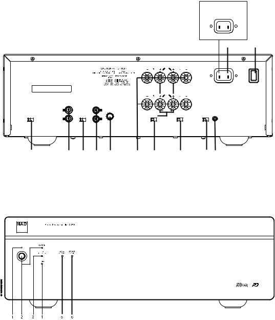
REAR PANEL CONNECTIONS (FIGURE 1)
© NAD 2003 C272
EUROPEAN
VERSION ONLY
AC IN ~
|
|
|
|
|
|
|
|
|
|
|
230V~50HZ |
|
|
|
|
|
|
|
|
|
|
|
|
10 |
11 |
|
|
|
|
|
|
|
SPEAKERS A |
|
|
|
|
VACATION |
|
|
|
|
|
|
|
|
|
|
AC IN ~ |
ON |
|
|
|
|
|
|
|
|
|
|
|
|
|
|
|
Serial No./No. De Series |
|
|
|
|
|
|
|
|
|
120V~60HZ |
OFF |
|
|
|
|
|
|
|
|
|
|
|
|
|
|
|
|
|
|
|
|
SPEAKERS B |
|
|
|
|
|
|
|
FIXED IN |
|
VARIABLE IN |
|
|
|
|
|
|
|
|
|
|
|
|
INPUT |
|
|
|
|
|
|
|
|
|
|
|
|
LEVEL |
|
|
|
|
|
|
|
|
|
|
L |
|
L |
(dB) |
|
MONO |
|
|
|
|
|
|
|
|
|
|
|
|
|
|
|
|
||
|
|
|
|
|
|
|
|
|
SOFT |
|
+12V TRIGGER |
|
|
|
|
INPUT |
|
|
|
BRIDGE |
|
|
IN |
|
|
|
|
|
SELECT |
|
|
|
MODE |
|
CLIPPING |
|
|
|
|
|
R |
|
R |
|
|
|
|
|
|
|
|
SENSE/ |
SLEEP/ |
FIX |
VAR |
MIN |
MAX |
ON |
OFF |
ON |
OFF |
AUTO |
OFF |
|
DEFEAT |
WAKE |
|
|
|
|
(MONO) |
(STEREO) |
|
|
|
100mA |
|
|
|
|
|
|
|
(LEFT CH.) |
|
|
|
|
|
|
12 |
1 |
2 |
3 |
4 |
5 |
6 |
7 |
8 |
9 |
FRONT PANEL CONTROLS (FIGURE 2)
3

NAD C 272 Stereo Power Amplifier
QUICK START
1. Connect the speakers to the Speaker A terminals and preamplifier to the “FIXED IN” inputs.
2. Plug in the AC power cord.
3. Press the POWER button to turn the NAD C 272 on. 4. Press the required input selector.
NOTES ON INSTALLATION
Your NAD C 272 should be placed on a firm, level surface. Avoid placing the unit in direct sunlight or near sources of heat and damp. Allow adequate ventilation. Do not place the unit on a soft surface like a carpet. Do not place it in an enclosed position, such a bookcase or cabinet, that may impede the airflow through the ventilation slots. Make sure the unit is switched off before making any connections.
The RCA sockets on your NAD C 272 are colour coded for convenience. Red and white are Right and Left audio respectively. Use high quality leads and sockets for optimum performance and reliability. Ensure that leads and sockets are not damaged in any way and all sockets are firmly pushed home.
For best performance, use quality speaker leads of 16 gauge (1.5mm) thickness or more. If the unit is not going to be used for some time, disconnect the plug from the AC socket.
Should water get into your NAD C 272, shut off the power to the unit and remove the plug from the AC socket. Have the unit inspected by a qualified service technician before attempting to use it again. DO NOT REMOVE THE COVER, THERE ARE NO
USER-SERVICEABLE PARTS INSIDE.
Use a dry soft cloth to clean the unit. If necessary, lightly dampen the cloth with soapy water. Do not use solutions containing benzol or other volatile agents.
REAR PANEL CONNECTIONS (FIGURE 1)
GB |
1. FIXED IN |
|
|
|
The Fixed Inputs take the input signal straight to the power |
|
amplifier’s circuitry. This set of inputs is normally used in a system |
|
with only one power amplifier or multiple but identical power |
|
amplifiers. Refer also to section “Variable In” in this chapter for |
|
more information. |
|
Connect the output from a pre-amplifier or processor, such as a |
|
surround-sound decoder, to this set of inputs. Use a twin RCA-to- |
|
RCA lead to connect to the left and right ‘Audio Output’ of the |
|
pre-amp or processor to the Fixed-In sockets. |
|
NOTES: Always turn the C 272 and other components in the |
|
system off before connecting or It is disconnecting anything to the |
|
“Fixed In” or Variable In” sockets. |
|
When using the Fixed In sockets, make sure the “Input Select” |
|
switch (No.2) is to the “Fix” position. |
|
2. INPUT SELECT |
|
The Input Select switch determines which input on the C 272 is |
|
active. Set to “FIX” for use with “Fixed In” and to “VAR” for use |
|
with “Variable In”. Refer also to section “Variable In” in this |
|
chapter for more information. |
3. VARIABLE IN
Using the Variable inputs, it is possible to adjust the volume level for both channels simultaneously, using the Input Level Control (No. 4). This can be useful for:
•Level matching
In a surround sound or system with more than one set of speakers, differences in levels can occur due to variances in efficiency between these speakers. In case your preamplifier or processor also has individual trims for each channel, set these to neutral or mid position (usually marked as 0dB). Adjust the Level Control so that the speakers driven by the C 272 have the correct volume level compared to the other speakers, judging from your listening position.
•Extended volume control range
Many systems have so much voltage gain that the speakers (or your ears) are overdriven at any volume control setting higher than 11 or 12 o’clock. As a result you are confined to using only the lower half of the volume control’s range, where adjustments are imprecise and where channel balance errors tend to be greater. If the input level is reduced, you can turn up your processor’s or preamplifier’s volume control, making more effective use of its range. (Suggestion: adjust the input level controls so that your preferred maximum sound levels usually occur at about 2 or 3 o’clock on the volume control.) As an added benefit, this procedure suppresses any noise produced by the preamp’s high level circuitry (e.g. any residual hum or hiss that does not go away when the Volume is turned down).
•Bi-Amping
Some loudspeakers have separate connection terminals for the LF (Low Frequency) and HF (High Frequency) sections of the speaker. This facility allows to “Bi-Amp” such speakers, where a separate power amplifier is used for the LF and HF section, which may improve overall sound quality. When Bi-Amping with different models of power amplifiers, it is likely to occur that one power amplifier has more “gain” than the other, resulting in a mis-match in level for the woofer and tweeter of the speaker. Adjust the level control so that woofer and tweeter are in perfect balance with each other (identical gain of power amplifiers).
Connect the output from a pre-amplifier or processor, such as a surround-sound decoder, to this set of inputs. Use a twin RCA-to- RCA lead to connect to the left and right ‘Audio Output’ of the pre-amp or processor to the Fixed-In sockets.
NOTES: Always turn the C 272 and other components in the system off before connecting or disconnecting anything to the “Fixed In” or Variable In” sockets.
When using the “Variable In” sockets, make sure the “input Select” switch (No.2) is to the “VAR” position.
4. INPUT LEVEL CONTROL
The Input Level control works in combination with “Variable In” (No. 3) only. With the control the volume to the power amplifier can be adjusted from zero (counter clock-wise) to maximum (turned up all the way clock-wise). Refer also to section “Variable In” in this chapter for more information.
NOTE: Always turn the C 272 and other components in the system off before connecting or disconnecting anything to the “Fixed In” or Variable In” sockets.
4

5. SPEAKERS A & SPEAKERS B
The NAD C 272 is equipped with two sets of speaker connectors wired in parallel to facilitate connection of multiple pairs of speakers or “Bi-Wiring”. Use the Speakers A connectors for the ‘main’ speakers and use the Speakers B connectors for a second pair, for example, extension speakers located in another room.
Under normal operation, connect the right speaker to the terminals market ‘R +’ and ‘R-’ ensuring that the ‘R+’ is connected to the ‘+’ terminal on your loudspeaker and the ‘R-’ is connected to the loudspeaker’s ‘-’ terminal. Connect the terminals marked ‘L+’ and ‘L-’ to the left speaker in the same way.
In Bridge Mode, connect the single speaker to the terminals marked ‘R +’ and ‘L+’ ensuring that the ‘L+’ is connected to the ‘+’ terminal on your loudspeaker and the R+ is connected to the loudspeaker’s ‘-’ terminal. Refer also to section “Bridge Mode” in this chapter (No. 6).
Always use heavy duty (16 gauge; 1.5mm, or thicker) stranded wire to connect loudspeakers to your NAD C 272. The high-current binding post terminals can be used as a screw terminal for cables terminating in spade or pin sockets or for cables with bare wire ends.
BARE WIRES AND PIN CONNECTORS
Bare wires and pin sockets should be inserted into the hole in the shaft of the terminal. Unscrew the speaker terminal’s plastic bushing until the hole in the screw shaft is revealed. Insert the pin or bare cable end into the hole and secure the cable by tightening down the terminal’s bushing. Ensure bare wire from the speaker cables does not touch the back panel or another socket . Ensure that there is only 1/2” (1cm) of bare cable or pin and no loose strands of speakers wire.
NOTE: Make sure the speaker impedance is 4 ohms or more when connecting only one pair of speakers; make sure the speaker impedance for all speakers is over 8 ohms when connecting two sets of speakers. In Bridge Mode, the impedance of the loudspeaker should also be 8 ohms or higher.
Always turn the C 272 and other components in the system off before connecting or disconnecting speakers.
6. BRIDGE MODE
The stereo NAD C 272 power amplifier can be configured to be mono (Bridge Mode), more than doubling its output power: 2 x 120 vs. 1 x 300 Watt. This way, the NAD C 272 can be used as part of a high power stereo or home-theatre system, by connecting adding additional power amplifiers.
Set the BRIDGE MODE switch to the “Bridge” position and connect the speaker to the terminals marked ‘L +’ and ‘R+’ ensuring that the ‘L+’ is connected to the ‘+’ terminal on your loudspeaker and the ‘R+’ is connected to the loudspeaker’s ‘-’ terminal. Connect the source to the Left FIXED, or VARIABLE input.
In Bridged Mode the NAD C 272 will produce approximately 300W into an 8 ohm loudspeaker. In this mode, the amplifier sections will react as though the speaker impedance has been halved. Low impedance speakers (under 8 ohms) are not recommended when using Bridge Mode, as these may cause the amplifier’s thermal cutout to operate if played at high levels.
The Bridge Mode indicator on the front panel (Fig. 2; No. 6) will illuminate when the amplifier is in Bridge mode.
NOTES: Do not connect anything to the Right “Fixed In” or Right “Variable In” sockets when Bridge Mode is selected.
Always turn the C 272 and other components in the system off before connecting or disconnecting anything to the “Fixed In” or Variable In” sockets.
7. SOFT CLIPPING™
When an amplifier is driven beyond its specified power output, a hard, distorted sound can be heard on very loud sounds. This is caused by the amplifier cutting off or ‘hard clipping’ the peaks of sound that it was not designed to reproduce. The NAD Soft Clipping™ circuit gently limits the output of the system to minimise audible distortion if the amplifier is overdriven.
If your listening involves moderate power levels you may leave the Soft Clipping™ switch to Off. If you are likely to play at high levels, that could stretch the amplifier’s power capability, then switch Soft Clipping™ On.
The Soft Clipping™ indicator on the front panel will illuminate when the amplifier is in Soft Clip mode.
8. 12V TRIGGER AUTO ON-OFF
The C 272’s 12V trigger input allows it to be switched to On and Stand-by remotely by an external component.
Set the 12V Trigger switch set to the “ON” position to activate the 12V Trigger input. When the switch is set to the Off position, the 12V trigger input is not active. Refer to section “12V Trigger In” below for more information.
9. 12V TRIGGER IN
This input allows the C 272 to be switched remotely to stand-by and on or by ancillary equipment such as a preamp, AV processor, etc. which are also equipped with a 12V trigger output.
For switching Stand-by/Power On of the C 272 by an external component, connect the12V-trigger input of the C 272 to the remote component’s DC output jack. The plug required is a standard 3.5mm Mini-Jack plug (“mono”): The tip is the live or +
connection, the shaft of the input jack is the 12V-trigger - or GB ground connection.
NOTES: The C 272’s 12V Trigger will work within a range of 6 to 15 V DC level and typically draws less than 10mA of current. Check the specifications of the Trigger output terminal on the remote component to ensure it is compatible with the C 272’s 12V-trigger input. NAD components equipped with 12V output triggers are fully compatible with the C 272’s 12V input trigger.
Before making any connections to any 12V trigger input or output, make sure all components are disconnected from the AC mains.
Failure to observe the above may result in damage to the C 272 or any ancillary components attached to it. If in doubt over the connections, installation and operation of the 12V trigger output consult your NAD dealer.
10. AC LINE CORD
Plug the AC power cord into a live AC wall socket. Make sure all connections have been made before connecting to mains.
11. VACATION ON/OFF
The VACATION switch is the master on/off control for the amplifier. When the switch is in the ON state the amplifier is in standby as shown
5

by the amber LED above the power switch on the front panel. If the amplifier will not be used for an extended period of time, switch the VACATION switch to the OFF position.
12. SLEEP/WAKE-SENSE/DEFEAT
The SLEEP/WAKE, SENSE/DEFEAT switch logic controls the standby/on-state of the amplifier via the presences or absence of audio signal at the amplifier channel inputs. The SLEEP/WAKE, SENSE/DEFEAT switch must be in the SLEEP/WAKE position in order to use this logic. When the SLEEP/WAKE, SENSE/DEFEAT switch is in the SENSE/DEFEAT position, this logic control is deactivated.
When the switch is in the SLEEP/WAKE position, the C 272 amplifier will instantaneously turn on from a standby state, sensing any input signal from any channel as seen by a lit green SENSE LED on the front panel of the amplifier (approximately above 20mV RMS input). If all of the audio signals are absent for approximately 5 minutes, the amplifier will switch automatically to standby condition, with the green SENSE LED off, and the amber LED over the front panel switch lit.
FRONT PANEL CONTROLS (FIGURE 2)
1. STAND-BY/PROTECTION INDICATOR
Upon switching Power on, the indicator will light up red and after a short pause turn to green to indicate the amplifier is ready for use.
In cases of serious abuse of the amplifier, such as overheating, excessively low loudspeaker impedance, short circuit, etc. the amplifier will engage its Protection circuitry. The indicator will light up red and the sound will be muted. In such a case, turn the amplifier off, wait for it to cool down and/or check the speaker connections, making sure the overall loudspeaker impedance doesn’t go below 4 ohms or 8 ohms in Bridge Mode. Once the cause for the protection circuitry to engage has been removed, switch the amplifier On again.
|
The diagram below shows the operation of the Stand- |
|||
|
by/protection indicator: |
|
|
|
|
|
|
|
|
|
|
Green |
Amber |
Red |
|
Normal Operation |
• |
|
|
GB |
Stand-by |
|
• |
|
Protection |
|
|
• |
|
|
|
|
||
|
|
|
|
|
2. POWER ON/OFF
Press this button to switch the amplifier on or off. The Power On/Standby (No. 1) indicator located just above the power button and Protection indicator will light up. After a few seconds, the Protection LED will turn off, indicating that the amplifier is ready for use.
3. TRIGGER INDICATOR
The 12V-TRIGGER LED illuminates green when the amplifier switches from standby to power on state via the 12V input (refer to “Rear-Panel Connections”: 12V-TRIGGER INPUT section). Once you turn on the amplifier via the 12V-IN TRIGGER, only the absence of the 12V can return the amplifier to standby state.
4. SENSE INDICATOR
The SENSE LED illuminates green when the amplifier senses a signal greater than 20mV RMS on any of the amplifier inputs refer to “RearPanel Controls and Connections”: SLEEP/WAKE, SENSE/DEFEAT section). Once you turn on the amplifier via the SLEEP/WAKE sense logic, only the absence of a signal to all the amplifier’s inputs can return the amplifier to standby state.
5. SOFT CLIPPING™ INDICATOR
The green SOFT CLIPPING™ indicator shows that the Soft Clipping™ mode is engaged. Refer also to chapter “Rear Panel Connections”, section 7; “Soft Clipping™” for more information.
6. BRIDGE MODE INDICATOR
The BRIDE MODE indicator lights up (amber) when the C 272 is switched to Bridge Mode. Refer also to chapter “Rear Panel Connections”, section 6, “Bridge Mode” for more information.
6

ATO LOGIC
The C 272 amplifier may be turned on in any one of three discrete ways for complete system flexibility: From the front-panel switch, the 12VTRIGGER circuit, or by a “SLEEP/WAKE” signal-sensing circuit. The ON/OFF power control is managed by the Automated Turn-On logic or ATO Logic circuit that requires the amplifier to be switched back to standby in the same manner by which it was activated. In other words, if the amplifier is switched on via a 12V-control signal, it cannot be switched to standby via the front-panel switch, it must wait for removal of the 12V-control signal. In practice, you probably would use only one of the methods once the NAD C 272 amplifier is installed.
ATO LOGIC CHART
SWITCH |
Amber LED over |
Green |
Green |
Green |
|
front power switch |
SWITCH LED |
12V-TRIGGER LED |
SENSE LED |
|
|
|
|
||||
VACATION switch set to OFF |
OFF |
OFF |
OFF |
OFF |
|
|
|
|
|
|
|
VACATION switch set to ON |
Amber |
OFF |
OFF |
OFF |
|
|
|
|
|
|
|
Press front power switch with |
Green |
ON |
OFF |
OFF |
|
VACATION switch set to ON |
|
||||
|
|
|
|
|
|
|
|
|
|
|
|
Press front power switch with |
Amber |
OFF |
OFF |
OFF |
|
VACATION switch set to ON |
|
||||
|
|
|
|
|
|
|
|
|
|
|
|
12V TRIGGER |
Amber LED over |
Green |
Green |
Green |
|
front power switch |
SWITCH LED |
12V-TRIGGER LED |
SENSE LED |
|
|
|
|
||||
VACATION switch set to OFF |
OFF |
OFF |
OFF |
OFF |
|
|
|
|
|
|
|
VACATION switch set to ON |
Amber |
OFF |
OFF |
OFF |
|
|
|
|
|
|
|
12 V INPUT TRIGGER = 0V with |
Amber |
OFF |
OFF |
OFF |
|
VACATION switch set to ON |
|
||||
|
|
|
|
|
|
|
|
|
|
|
|
12V INPUT TRIGGER = 12V with |
Green |
OFF |
ON |
OFF |
|
VACATION switch set to ON |
|
||||
|
|
|
|
|
|
|
|
|
|
|
|
SLEEP/WAKE |
Amber LED over |
Green |
Green |
Green |
|
front power switch |
SWITCH LED |
12V-TRIGGER LED |
SENSE LED |
|
|
|
|
||||
VACATION switch set to OFF |
OFF |
OFF |
OFF |
OFF |
|
|
|
|
|
|
|
VACATION switch set to ON |
Amber |
OFF |
OFF |
OFF |
|
|
|
|
|
|
|
SLEEP/WAKE SENSE DEFEAT switch |
|
|
|
|
|
set to SENSE DEFEAT with VACATION |
Amber |
OFF |
OFF |
OFF |
|
switch set to ON |
|
|
|
|
|
SLEEP/WAKE SENSE DEFEAT switch |
|
|
|
|
|
set to SLEEP/WAKE and any source |
Green |
OFF |
OFF |
ON |
|
input greater than 20mV with |
|
||||
|
|
|
|
|
|
VACATION switch set to ON |
|
|
|
|
|
|
|
|
|
|
|
GB
7

TROUBLESHOOTING
Problem |
Cause |
Solution |
|
|
|
NO SOUND |
• Power AC lead unplugged or power not |
• Check if AC lead is plugged in and |
|
switched on |
power switched on |
|
• Input Select switch not set to active input |
• Set switch to the active input |
|
• Input Level Control turned down |
• Turn control up to the correct level |
|
|
|
NO SOUND ONE CHANNEL |
• Balance control not centred |
• Centre Balance control |
|
• Speaker not properly connected or |
• Check connections and speakers |
|
damaged |
|
|
• Input lead disconnected or damaged |
• Check leads and connections |
|
|
|
WEAK BASS / DIFFUSE OR |
• Speakers wired out of phase |
• Check connections to all speakers in the |
NO STEREO IMAGE |
• Bridge Mode selected when speakers |
system |
|
are connected normally |
• Disengage Bridge Mode |
|
|
|
POWER/PROTECTION LED STAYS RED |
• Loudspeakers cabling has a short-circuit |
• Turn amplifier off and check |
UPON TURNING POWER ON |
|
loudspeaker cable connections for both |
|
|
speakers at amplifier’s back panel and |
|
|
loudspeakers. Turn amplifier on |
|
|
|
POWER/PROTECTION INDICATOR TURNS |
• Amplifier has over-heated |
• Turn amplifier off. Make sure ventilation |
RED DURING OPERATION |
• Overall impedance of loudspeakers |
slots on top and bottom of amplifier |
|
too low |
aren’t blocked. After amplifier has |
|
|
cooled down, turn back on |
|
|
• Ensure the overall loudspeaker |
|
|
impedance isn’t below 4 ohms |
|
|
• Check loudspeaker cables for |
|
|
short circuits |
|
|
|
GB
#

GB
9

Amplificateur de Puissance NAD C 272
MISE EN ROUTE RAPIDE
1.Connectez les haut-parleurs aux bornes Haut-Parleur A et branchez le préamplificateur aux entrées Entrée Fixe [FIXED IN].
2.Branchez le cordon d’alimentation secteur.
3.Appuyez sur le bouton-poussoir ALIMENTATION [POWER] pour mettre le NAD C 272 sous tension.
4.Appuyez sur le sélecteur d’entrée requis.
|
NOTES CONCERNANT L’INSTALLATION |
|
POSER LE NAD C 272 SUR UNE SURFACE STABLE, PLANE ET |
|
HORIZONTALE. EVITER LES RAYONS DIRECTS DU SOLEIL ET LES |
|
SOURCES DE CHALEUR ET D’HUMIDITÉ. ASSURER UNE |
|
VENTILATION ADÉQUATE. NE POSEZ PAS CET APPAREIL SUR |
|
UNE SURFACE MOLLE (MOQUETTE, PAR EXEMPLE). NE PAS LE |
|
PLACER DANS UN ENDROIT CONFINÉ (SUR UNE ÉTAGÈRE DE |
|
BIBLIOTHÈQUE OU DERRIÈRE DES PORTES VITRÉES), OÙ LE |
|
FLUX D’AIR À TRAVERS LES OUÏES DE VENTILATION RISQUE |
|
D’ÊTRE ENTRAVÉ. VÉRIFIER QUE L’APPAREIL EST MIS HORS |
|
TENSION AVANT DE RÉALISER DES CONNEXIONS |
|
QUELCONQUES. |
|
Pour vous faciliter la tâche, les bornes RCA de votre NAD C 272 |
|
sont codées couleur. Rouge pour l’audio droite, blanc pour l’audio |
|
gauche. N’utiliser que des câbles et des connecteurs de très bonne |
|
qualité de manière à obtenir un branchement dont la fiabilité est |
|
parfaite et les performances optimales. Vérifier que les câbles et les |
|
connecteurs ne présentent aucune détérioration, et que tous les |
|
connecteurs sont bien enfoncés jusqu’en butée. |
|
Pour obtenir les meilleures performances, utiliser des câbles de |
|
haut-parleurs d’une épaisseur égale ou supérieure au calibre 16 |
|
(1,5 mm) ou plus. Si l’appareil doit rester inutilisé pendant un |
|
certain temps, débrancher le cordon d’alimentation de la prise de |
|
secteur murale. |
|
Si de l’eau pénètre à l’intérieur de votre NAD C 272, couper |
|
l’alimentation de l’appareil et retirer la fiche de la prise secteur. |
|
Faire contrôler l’appareil par un technicien de service après-vente |
|
qualifié, avant toute tentative de remise en service. Ne pas retirer |
|
le couvercle. A l’intérieur, il n’y a aucun élément sur lequel |
F |
l’utilisateur peut intervenir. |
Utiliser un chiffon doux sec et propre pour nettoyer l’appareil. Si |
|
nécessaire, humecter le chiffon avec un peu d’eau savonneuse. Ne |
|
|
pas utiliser de solution contenant du benzol ou un quelconque |
|
autre agent volatile. |
|
BRANCHEMENTS SUR LE PANNEAU ARRIERE (FIGURE 1) |
|
1. ENTREE FIXE [FIXED IN] |
|
Les Entrées Fixes relient le signal d’entrée directement aux circuits |
|
de l’amplificateur de puissance. Ces entrées sont normalement |
|
utilisées sur une chaîne comportant un seul amplificateur de |
|
puissance, ou plusieurs amplificateurs de puissance identiques. |
|
Voir aussi la section “Entrée Variable” de ce même chapitre pour |
|
plus d’informations. |
|
Branchez la sortie d’un préamplificateur ou d’un processeur, |
|
comme par exemple un décodeur de sonorisation enveloppante, à |
|
cet ensemble d’entrées. Utilisez un câble jumelé RCA vers RCA |
|
pour brancher le connecteur de Sortie Audio [Audio-Output] |
|
gauche et droit du préamplificateur ou processeur aux prises |
d’Entrée Variable [Variable In].
NOTES: Vous devez toujours mettre le C 272 et les autres modules de la chaîne hors tension avant de brancher (ou de débrancher) un quelconque appareil aux (des) prises d’Entrée Fixe ou Variable [Fixed In ou Variable In]. Lorsque vous utilisez les prises d’Entrée Fixe [Fixed In], veillez à ce que le Sélecteur d’Entrées [Input Select] (N° 2) soit à la position FIX.
2. SELECTEUR D’ENTREES [INPUT SELECT]
Le Sélecteur d’Entrées [Input Select] détermine laquelle des entrées du C 272 est active. La régler sur FIXE [FIX] pour une utilisation avec l’Entrée Fixe [Fixed In] ou sur VARIABLE [VAR] pour une utilisation avec l’Entrée Variable [[Variable In].
Voir aussi la section “Entrée Variable” de ce même chapitre pour plus d’informations.
3. VARIABLE IN
Il est possible, en se servant des Entrées Variables, d’ajuster le niveau de volume sonore des deux voies en même temps, grâce à la Commande de Niveau d’Entrée [Input Level Control] (N° 4). Cela peut être utile pour :
•Equilibrage des niveaux d’entrée
Sur une chaîne à sonorisation enveloppante ou dotée de plus d’un ensemble de haut-parleurs, il peut exister des différences de niveau dues aux rendements variables des différents hautparleurs utilisés. Si votre préamplificateur ou votre processeur comporte ses propres réglages individuels pour chaque voie, réglez ces commandes à leur position neutre ou moyenne (généralement repérée “0 dB”). Réglez ensuite la Commande de Niveau de manière à ce que les haut-parleurs pilotés par le C 272 aient un niveau de volume correct comparé à celui des autres haut-parleurs, en écoutant depuis votre place habituelle.
•Augmentation de la plage de réglage du volume sonore
Nombreuses sont les chaînes stéréo dont le gain en tension est tellement important que les haut parleurs (et par conséquent les oreilles de l’auditeur) sont surchargés dès que l’on règle la commande de volume au delà de la position 11 heures ou 12 heures. Il s’en suit que la plage utile de la commande de volume sonore est limitée à sa moitié inférieure, plage dans laquelle les réglages sont imprécis et où les erreurs d’équilibrage des voies ont tendance à être plus importantes. En diminuant le réglage du niveau d’entrée, il devient possible d’augmenter le volume sonore de votre processeur ou de votre préamplificateur et d’utiliser la plupart de sa plage de réglage. (Suggestion : réglez les commandes de niveau d’entrée de manière à ce que les niveaux sonores maximum souhaitables se trouvent à environ 2 ou 3 heures sur la commande de volume sonore). Autre avantage : cette procédure élimine tout bruit généré par les circuits haut-niveau du préamplificateur (par exemple le bourdonnement ou le sifflement qui ne disparaît pas lorsque le Volume est au minimum).
10
•Bi-Amplificateurs
Certains haut-parleurs comportent des branchements distincts pour les sections BF (Basses Fréquences) et HF (Hautes Fréquences) de l’enceinte. Ce dispositif permet d’utiliser ces haut-parleurs en mode “Bi-Amplificateurs”, grâce auquel un amplificateur de puissance distinct est utilisé pour chaque section, BF et HF. Cela peut améliorer la qualité globale de la sonorité. Lorsque vous utilisez une configuration BiAmplificateurs comportant des modèles d’amplificateurs de puissance non identiques, il est probable que l’un des amplificateurs ait un “gain” plus important que celui de l’autre, ce qui entraîne un déséquilibrage au niveau du woofer et du tweeter du haut-parleur. Réglez la commande de niveau de manière à ce que l’équilibre entre le woofer et le tweeter soit parfait (gain identique pour les deux amplificateurs).
Branchez la sortie d’un préamplificateur ou d’un processeur, comme par exemple un décodeur de sonorisation enveloppante, à cet ensemble d’entrées. Utilisez un câble jumelé RCA vers RCA pour brancher le connecteur de Sortie Audio [Audio-Output] gauche et droit du préamplificateur ou processeur aux prises d’Entrée Variable [Variable In].
NOTES: Vous devez toujours mettre le C 272 et les autres modules de la chaîne hors tension avant de brancher (ou de débrancher) un quelconque appareil aux (des) prises d’Entrée Fixe ou Variable [Fixed In ou Variable In].
Lorsque vous utilisez les prises d’Entrée Variable [Variable In], veillez à ce que le Sélecteur d’Entrées [Input Select] (N° 2) soit à la position VAR.
4. COMMANDE DE NIVEAU D’ENTREE [INPUT LEVEL]
La commande de Niveau d’Entrée [Input Level] n’a d’effet que sur l’Entrée Variable [Variable In] (N° 3). Grâce à cette commande, le volume sonore de l’amplificateur est réglable de zéro (butée antihoraire) à maximum (butée horaire). Voir aussi la section “Entrée Variable” de ce même chapitre pour plus d’informations.
NOTA: Vous devez toujours mettre le C 272 et les autres modules de la chaîne hors tension avant de brancher (ou de débrancher) un quelconque appareil aux (des) prises d’Entrée Fixe ou Variable [Fixed In ou Variable In].
5. HAUT-PARLEURS A & HAUT-PARLEURS B
Le NAD C 272 est équipé de deux jeux de connecteurs pour hautparleurs, câblés en parallèle, afin de faciliter le branchement de plusieurs paires de haut-parleurs (“Bi-Câblage”). Utilisez les connecteurs Haut-Parleurs A [Speakers A] pour connecter les hautparleurs “principaux” et utilisez les connecteurs Haut-Parleurs B [Speakers B] pour connecter (par exemple) une deuxième paire de haut-parleurs située dans une autre pièce.
En fonctionnement normal, connectez le haut-parleur droit aux bornes repérées “R+” et “R-”, en vous assurant que la borne “R+” est reliée à la borne “+” du haut-parleur et que la borne “R-” est reliée à la borne “-” du haut-parleur. Branchez les bornes repérées “L+” et “L-” au haut-parleur gauche en procédant de la même manière.
En Mode Ponté [Bridge], branchez le haut-parleur unique aux bornes repérées “R+” et “L+” en vous assurant que la borne “L+” est reliée à la borne “+” de votre haut-parleur et que la borne “R+” est reliée à la borne “-” du haut-parleur. Reportez-vous aussi à la section “Mode Ponté” de ce même chapitre (N° 6).
N’utilisez que du fil torsadé haute puissance (calibre 16 ; 1,5 mm ou plus) pour brancher les haut-parleurs à votre NAD C 272.
On peut utiliser les bornes pour courants élevés comme bornes à visser pour les câbles comportant des cosses plates, des broches ou des fils nus.
FILS NUS ET BORNES A BROCHES
Les fils nus et les broches s’insèrent dans le trou diamétral percé dans la tige de la borne. Desserrez la bague en plastique de la borne de haut-parleur jusqu’à ce que le trou axial dans la tige soit visible. Insérez la broche ou le fil nu dans le trou, puis fixez le câble en vissant la bague de la borne. Veillez à ce qu’aucun fil nu des câbles des haut-parleurs ne touche le panneau arrière ou une autre prise. Veillez à ce qu’il n’y ait que 1 cm (1/2”) de fil nu ou de broche et qu’il n’y ait aucun brin libre sur les fils des haut-parleurs.
NOTA: Assurez-vous que l’impédance des haut-parleurs est d’au moins 4 ohms si vous ne connectez qu’une paire de haut-parleurs ; assurez-vous que l’impédance de tous les haut-parleurs est d’au moins 8 ohms si vous connectez deux paires de haut-parleurs.
En Mode Ponté, l’impédance du haut-parleur unique doit aussi être d’au moins 8 ohms. Vous devez toujours mettre le C 272 et les autres modules de la chaîne hors tension avant de brancher ou de débrancher les haut-parleurs.
6. MODE PONTE
L’amplificateur de puissance stéréophonique NAD C 272 peut être configuré en mode monophonique (Mode Ponté [Bridge Mode]), pour obtenir une puissance de sortie plus que doublée : 2 x 120 Watts en mode stéréo pour 1 x 300 Watts en mode mono. Le NAD C 272 peut donc être utilisé comme élément d’une chaîne stéréophonique haute puissance ou d’une chaîne de Cinéma à Domicile ; il suffit de connecter d’autres amplificateurs à la chaîne.
Mettez le sélecteur de MODE PONTE [BRIDGE MODE] à la position Ponté [Bridge] et branchez le haut-parleur aux bornes repérées “L+” et “R+”, en vous assurant que la borne “L+” est reliée à la borne “+” du haut-parleur et que la borne “R+” est reliée à la borne “-” du haut-parleur. Connectez la source à l’Entrée Fixe [FIXED IN] Gauche ou à l’Entrée Variable [VARIABLE IN] Gauche.
En Mode Ponté, le NAD C 272 aura une puissance de sortie d’environ 300 W avec un haut-parleur de 8 ohms. Dans ce mode, les sections d’amplificateur fonctionneront comme si l’impédance du haut-parleur avait été divisée par deux. Pour cette raison, il est
déconseillé d’utiliser des haut-parleurs de faible impédance (moins F de 8 ohms) en Mode Ponté, car cela risquerait de provoquer le
déclenchement du dispositif de coupure thermique lorsque l’amplificateur fonctionne à puissance élevée.
L’indicateur de Mode Ponté [Bridge] de la face parlante (Fig. 2 ; N° 6) s’allume lorsque l’amplificateur fonctionne en mode Ponté.
NOTES: Il ne faut rien connecter aux prises d’Entrée Fixe [FIXED IN] Droite ou d’Entrée Variable [VARIABLE IN] Droite lorsque le Mode Ponté est sélectionné.
Vous devez toujours mettre le C 272 et les autres modules de la chaîne hors tension avant de brancher (ou de débrancher) un quelconque appareil aux (des) prises d’Entrée Fixe ou Variable [Fixed In ou Variable In].
11

|
7. ECRETAGE DOUX [SOFT CLIPPING™] |
|
Lorsqu’un amplificateur est poussé au-delà de sa puissance de |
|
sortie spécifiée, on entend un son dur et déformé lors des passages |
|
à sonorité forte. Cela provient du fait que l’amplificateur coupe ou |
|
“écrête de façon dure” les pointes sonores pour lesquelles sa |
|
conception ne permet pas la reproduction. Le circuit d’Ecrêtage |
|
Doux™, de NAD, limite en douceur la forme d’onde à la sortie, |
|
pour minimiser la distorsion audible lorsque l’amplificateur est |
|
poussé au-delà de ses limites. |
|
Si votre écoute comporte des niveaux modérés de puissance, vous |
|
pouvez laisser l’Ecrêtage Doux sur ARRET [OFF]. Si, par contre, vous |
|
pensez passer de la musique à des niveaux très élevés, susceptibles |
|
de dépasser la capacité de puissance de l’amplificateur, nous |
|
préconisons de mettre l’Ecrêtage Doux sur “MARCHE” [ON]. |
|
L’indicateur d’Ecrêtage Doux [Soft Clipping™] sur la face parlante |
|
s’allume lorsque l’amplificateur est en mode Ecrêtage Doux. |
|
8. MARCHE-ARRET AUTO ASSERVISSEMENT 12 V [12V |
|
TRIGGER] |
|
L’entrée Asservissement 12 V du C 272 permet d’assurer la mise en |
|
Marche ou en Veille de l’appareil à distance, à partir d’un module |
|
externe. |
|
Mettez l’interrupteur Asservissement 12 V [12V Trigger] à la |
|
position MARCHE [ON] pour activer l’entrée Asservissement 12 V. |
|
Lorsque cet interrupteur est en position Arrêt [Off], l’entrée |
|
d’asservissement 12 V n’est pas active. Voir la section “Entrée |
|
Asservissement 12 V” ci-dessous, pour plus d’informations. |
|
9. ENTREE ASSERVISSEMENT 12 V |
|
[12 V TRIGGER IN] |
|
Cette entrée permet d’assurer la mise en Veille ou en Marche du C |
|
272 à partir d’un appareil externe, comme par exemple un |
|
préamplificateur, un processeur AV, etc ..., dans la mesure où cet |
|
appareil est doté d’une sortie d’asservissement 12 V. |
|
Pour permettre la mise en Veille ou en Marche du C 272 à partir d’un |
|
module externe, connectez l’entrée d’asservissement 12 V du C 272 |
|
au jack de sortie CC du module externe. Le connecteur requis est |
|
une fiche Mini-Jack standard de 3,5 mm (“mono”) : L’extrémité de |
|
la fiche jack correspond au “+” et la tige correspond à |
F |
l’asservissement 12 V, c’est à dire au “-” ou à la masse. |
NOTES: L’Asservissement 12 V du C 272 fonctionne dans une |
|
plage de tension de 6 à 15 V CC, et sa consommation de courant |
|
|
est typiquement inférieure à 10 mA. Vérifiez les caractéristiques de |
|
la borne de sortie d’Asservissement du module externe pour vous |
|
assurer qu’elles sont compatibles avec l’entrée d’Asservissement |
|
12 V du C 272. Tous les appareils NAD équipés d’un |
|
Asservissement 12 V sont entièrement compatibles avec la sortie |
|
Asservissement 12 V du C 272. |
|
Avant de réaliser un quelconque branchement à une entrée ou à |
|
une sortie d’Asservissement 12 V, assurez-vous que tous les |
|
appareils sont débranchés du secteur. |
|
Tout non respect de la consigne ci-dessus pourrait provoquer la |
|
détérioration du C 272 ou de tout appareil auxiliaire qui lui est |
|
connecté. En cas de doute concernant les branchements, |
|
l’installation et l’utilisation de la sortie d’Asservissement 12 V, |
|
consultez votre revendeur NAD. |
10. CORDON ALIMENTATION SECTEUR
Branchez le cordon secteur à une prise de courant murale en état de marche. Veillez à ce que tous les branchements aient été faits avant de brancher le cordon au secteur.
11. SÉLECTEUR VACATION ON/OFF
Le sélecteur VACANCES [VACATION] est la principale commande marche/arrêt de l’amplificateur. Lorsque l’interrupteur est en position Marche, l’amplificateur est en veille et la LED orange au dessus du bouton Marche/Arrêt de la face parlante s’allume. Si l’amplificateur doit rester inutilisé pendant une longue période, mettez le sélecteur VACANCES en position VACANCES [VACATION].
12. SÉLECTEUR SLEEP/WAKE, SENSE/DEFEAT
La logique du sélecteur VEILLE/ÉVEIL - CAPTEUR INHIBÉ [SLEEP/WAKE, SENSE/DEFEAT] gère l’état de veille/marche de l’amplificateur en fonction de l’absence ou de la présence d’un signal audio sur les entrées sur les voies d’entrée de l’amplificateur. Le sélecteur VEILLE/ÉVEIL - CAPTEUR INHIBÉ doit être en position VEILLE/ÉVEIL [SLEEP/WAKE] afin de pouvoir utiliser cette logique. Lorsque sélecteur VEILLE/ÉVEIL - CAPTEUR INHIBÉ est en position CAPTEUR INHIBÉ [SENSE/DEFEAT], cette commande logique est désactivée.
Lorsque le sélecteur est en position VEILLE/ÉVEIL [SLEEP/WAKE], l’amplificateur NAD série CI passe instantanément en mode marche, à partir du mode veille, dès qu’il détecte un signal sur une voie quelconque, ce qui est indiqué par l’allumage d’une LED verte CAPTEUR [SENSE] sur la face parlante (signal d’entrée supérieur à environ 20mV eff.). Si tous les signaux audio sont absents pendant environ 5 minutes, l’amplificateur repasse automatiquement en mode Veille, ce qui est indiqué par l’extinction de la LED CAPTEUR [SENSE] et l’allumage de la LED orange au dessus du bouton Marche/Arrêt de la face parlante.
COMMANDES SUR LA FACE PARLANTE (FIGURE 2)
1. LAMPE TÉMOIN DE VEILLE / PROTECTION [STANDBY/PROTECTION]
Après la mise sous tension, la lampe témoin s’allume en rouge puis, après une courte pause, passe au vert pour indiquer que l’amplificateur est prêt à fonctionner.
Dans le cas d’une très mauvaise utilisation de l’amplificateur, liée par exemple à une surchauffe, à des haut-parleurs d’impédance excessivement basse ou à un court-circuit, etc .., l’amplificateur activera ses circuits de Protection. La lampe témoin s’allumera en rouge et le son sera coupé. Dans un cas comme celui-ci, mettez l’amplificateur hors tension, attendez qu’il refroidisse et/ou vérifiez le branchement des haut-parleurs, et vérifiez que l’impédance globale des haut-parleurs ne passe pas en dessous de 4 ohms (ou 8 ohms en Mode Ponté). Après avoir éliminé la cause de l’activation des circuits de protection, remettez l’amplificateur sous tension.
Le schéma ci-dessous montre le fonctionnement de la lampe témoin de Veille / Protection :
|
Vert |
Orange |
Rouge |
Fonctionnement normal |
• |
|
|
Veille |
|
• |
|
Protection |
|
|
• |
|
|
|
|
2. MARCHE / ARRET [POWER ON/OFF]
Appuyez sur ce bouton pour mettre l’amplificateur sous tension ou hors tension. La lampe témoin Marche/Veille [Power On/Standby] (N° 1), située juste au dessus du bouton de mise sous tension et de l’indicateur de Protection s’allume. Après quelques secondes, la LED de Protection s’éteindra et l’amplificateur sera prêt à fonctionner.
12

3. INDICATEUR d’ASSERVISSEMENT [TRIGGER]
La LED d’ASSERVISSEMENT 12 V [12V-TRIGGER] s’allume en vert lorsque l’amplificateur passe du mode veille en mode marche suite à la présence d’un signal sur l’entrée 12 V (reportez-vous à la rubrique “Commandes et branchements sur le panneau arrière” : section ASSERVISSEMENT 12 V [12V-TRIGGER INPUT]). Après avoir mis l’amplificateur sous tension via l’ENTRÉE ASSERVISSEMENT 12 V [12V-IN TRIGGER], vous ne pourrez le remettre en état de veille qu’en faisant disparaître le signal 12 V.
4. INDICATEUR CAPTEUR [SENSE]
La LED CAPTEUR [SENSE] s’allume lorsque l’amplificateur reçoit un signal supérieur à 20mV eff. sur l’une de ses entrées (reportez-vous à la rubrique “Commandes et branchements sur le panneau arrière” : section VEILLE/ÉVEIL - CAPTEUR INHIBÉ [SLEEP/WAKE, SENSE/DEFEAT]). Après avoir mis l’amplificateur sous tension via la logique de détection VEILLE/ÉVEIL [SLEEP/WAKE], vous ne pourrez le remettre en état de veille qu’en faisant disparaître les signaux sur toutes les entrées de l’amplificateur.
5.INDICATEUR D’ECRETAGE DOUX [SOFT CLIPPING™]
L’indicateur vert d’ECRETAGE DOUX indique que le mode d’Ecrêtage [Doux Soft Clipping™] est actif. Reportez-vous aussi au chapitre “Branchements sur le panneau arrière”, section 7 “Ecrêtage Doux”, pour de plus amples informations.
6.INDICATEUR DE MODE PONTE
[BRIDGE MODE]
L’indicateur de MODE PONTE s’allume (orange) lorsque le C 272 est en Mode Ponté. Voir aussi le chapitre “Branchements sur le panneau arrière”, section 6 “Ecrêtage Doux” pour plus d’informations.
F
13

ATO LOGIC DE NAD
La mise en marche de l’amplificateur série CI peut être effectuée de trois façons distinctes, pour une flexibilité totale de la chaîne : 1) à l’aide de l’interrupteur de la face parlante, 2) via le circuit d’ASSERVISSEMENT 12 V [12V-TRIGGER], ou 3) via un circuit de détection de signal VEILLE/ÉVEIL [SLEEP/WAKE]. La commande MARCHE/ARRÊT [ON/OFF] est gérée par le circuit Logique de Mise en Marche Automatique [Automated TurnOn logic - ATO Logic], qui nécessite que l’on remette l’amplificateur en mode veille en utilisant la même commande que pour sa mise en marche. Autrement dit, si vous mettez l’amplificateur en marche grâce à un signal de commande 12 V, il est impossible de le remettre en veille à l’aide de l’interrupteur sur la face parlante ; l’amplificateur doit obligatoirement attendre la disparition du signal de commande 12 V. Dans la pratique, vous n’utiliserez qu’une seule de ces trois méthodes une fois l’installation de votre amplificateur NAD série CI terminée.
TABLEAU DE LOGIQUE DE MISE EN MARCHE AUTOMATIQUE [ATO LOGIC]
F
|
LED orange au |
|
|
|
|
INTERRUPTEUR [“SWITCH”] |
dessus de |
LED verte |
LED verte |
|
|
l’interrupteur de la |
INTERRUPTEUR |
d’ASSERVISSEMENT |
LED verte CAPTEUR |
||
|
|||||
|
face parlante |
[“SWITCH”] |
12 V [12V-TRIGGER] |
[SENSE] |
|
Interrupteur VACANCES [VACATION] |
ÉTEINTE |
ÉTEINTE |
ÉTEINTE |
ÉTEINTE |
|
en position [“OFF”] |
|||||
|
|
|
|
||
|
|
|
|
|
|
Interrupteur VACANCES [VACATION] |
ORANGE |
ÉTEINTE |
ARRÊT |
ÉTEINTE |
|
en position MARCHE [ON] |
|||||
|
|
|
|
||
|
|
|
|
|
|
Impulsion sur le bouton interrupteur |
|
|
|
|
|
d’alimentation sur la face parlante, |
|
|
|
|
|
alors que l’interrupteur VACANCES |
VERTE |
ALLUMÉE |
ÉTEINTE |
ÉTEINTE |
|
[VACATION] est en position MARCHE |
|
|
|
|
|
[ON] |
|
|
|
|
|
Nouvelle impulsion sur le bouton |
|
|
|
|
|
interrupteur d’alimentation sur la face |
|
|
|
|
|
parlante, alors que l’interrupteur |
ORANGE |
ÉTEINTE |
ÉTEINTE |
ÉTEINTE |
|
VACANCES [VACATION] est en |
|
|
|
|
|
position MARCHE [ON] |
|
|
|
|
|
d’ASSERVISSEMENT 12V |
LED orange au |
|
|
|
|
dessus de |
LED verte |
LED verte |
|
||
[12V-TRIGGER] |
l’interrupteur de la |
INTERRUPTEUR |
d’ASSERVISSEMENT |
LED verte CAPTEUR |
|
|
face parlante |
[“SWITCH”] |
12 V [12V-TRIGGER] |
[SENSE] |
|
Interrupteur VACANCES [VACATION] |
ÉTEINTE |
ÉTEINTE |
ÉTEINTE |
ÉTEINTE |
|
en position [“OFF”] |
|||||
|
|
|
|
||
|
|
|
|
|
|
Interrupteur VACANCES [VACATION] |
ORANGE |
ÉTEINTE |
ÉTEINTE |
ÉTEINTE |
|
en position MARCHE [“ON”] |
|||||
|
|
|
|
||
|
|
|
|
|
|
ENTRÉE ASSERVISSEMENT 12 V = 0 V |
|
|
|
|
|
avec Interrupteur VACANCES |
ORANGE |
ÉTEINTE |
ÉTEINTE |
ÉTEINTE |
|
[VACATION] en position MARCHE |
|||||
|
|
|
|
||
[“ON”] |
|
|
|
|
|
ENTRÉE ASSERVISSEMENT 12 V = 12 |
|
|
|
|
|
V avec Interrupteur VACANCES |
VERTE |
ÉTEINTE |
ALLUMÉE |
ÉTEINTE |
|
[VACATION] en position MARCHE |
|||||
|
|
|
|
||
[“ON”] |
|
|
|
|
|
|
LED orange au |
|
|
|
|
VEILLE/ÉVEIL [SLEEP/WAKE] |
dessus de |
LED verte |
LED verte |
|
|
l’interrupteur de la |
INTERRUPTEUR |
d’ASSERVISSEMENT |
LED verte CAPTEUR |
||
|
|||||
|
face parlante |
[“SWITCH”] |
12 V [12V-TRIGGER] |
[SENSE] |
|
Interrupteur VACANCES [VACATION] |
ÉTEINTE |
ÉTEINTE |
ÉTEINTE |
ÉTEINTE |
|
en position [“OFF”] |
|||||
|
|
|
|
||
|
|
|
|
|
|
Interrupteur VACANCES [VACATION] |
ORANGE |
ÉTEINTE |
ÉTEINTE |
ÉTEINTE |
|
en position “MARCHE” [“ON”] |
|||||
|
|
|
|
||
|
|
|
|
|
|
Sélecteur VEILLE/ÉVEIL - CAPTEUR |
|
|
|
|
|
INHIBÉ [SLEEP/WAKE - SENSE |
|
|
|
|
|
DEFEAT] en position CAPTEUR INHIBÉ |
ORANGE |
ÉTEINTE |
ÉTEINTE |
ÉTEINTE |
|
[SENSE DEFEAT) avec interrupteur |
|||||
|
|
|
|
||
VACANCES [VACATION] en position |
|
|
|
|
|
“MARCHE” [“ON”] |
|
|
|
|
|
Sélecteur VEILLE/ÉVEIL - CAPTEUR |
|
|
|
|
|
INHIBÉ [SLEEP/WAKE - SENSE |
|
|
|
|
|
DEFEAT] en position VEILLE/ÉVEIL |
|
|
|
|
|
[SLEEP/WAKE] et n’importe quelle |
VERTE |
ÉTEINTE |
ÉTEINTE |
ALLUMÉE |
|
entrée source est à plus de 20mV, |
|||||
|
|
|
|
||
avec interrupteur VACANCES |
|
|
|
|
|
[VACATION] en position “MARCHE” |
|
|
|
|
|
[“ON”] |
|
|
|
|
|
|
|
|
|
|
14
 Loading...