


Integrating the Cisco Catalyst Blade
Switch 3020 for the HP c-Class
BladeSystem into the Cisco Data
Center Network Architecture
Design Guide
© 2008 Cisco Systems, Inc. All rights reserved. This document is Cisco Public Information.

Design Guide
Contents |
|
Introduction ..................................................................................................................................... |
3 |
HP c-Class BladeSystem Enclosure Overview............................................................................. |
3 |
Cisco Catalyst Blade Switch 3020 for HP...................................................................................... |
5 |
Cisco Catalyst Blade Switch 3020 Features ................................................................................. |
6 |
Spanning Tree.............................................................................................................................. |
6 |
Traffic Monitoring.......................................................................................................................... |
8 |
Link Aggregation Protocols........................................................................................................... |
9 |
Data Center Network Architecture............................................................................................... |
10 |
Data Center Network Components............................................................................................. |
10 |
Aggregation Layer ...................................................................................................................... |
11 |
Access Layer.............................................................................................................................. |
11 |
High Availability .......................................................................................................................... |
12 |
Design Goals.............................................................................................................................. |
12 |
High Availability .......................................................................................................................... |
12 |
High Availability for the BladeSystem Switching Infrastructure .............................................. |
13 |
High Availability for the Blade Servers................................................................................... |
13 |
Scalability ................................................................................................................................... |
14 |
Physical Port Count ............................................................................................................... |
14 |
Slot Count .............................................................................................................................. |
15 |
Management .............................................................................................................................. |
16 |
Out-of-Band Management ..................................................................................................... |
16 |
In-Band Management ............................................................................................................ |
17 |
Serial Console Port................................................................................................................ |
17 |
Management Options............................................................................................................. |
18 |
HP c-Class BladeSystem iLO Connectivity............................................................................ |
18 |
Design and Implementation Details............................................................................................. |
18 |
Network Management Recommendations.................................................................................. |
18 |
Network Topologies Using the Cisco Catalyst Blade Switch 3020 ............................................. |
19 |
Recommended Topology....................................................................................................... |
19 |
Alternative Topology .............................................................................................................. |
22 |
Configuration Details .................................................................................................................. |
23 |
VLAN Configuration ............................................................................................................... |
24 |
RPVST+ Configuration .......................................................................................................... |
24 |
Inter-Switch Link Configuration .............................................................................................. |
24 |
Server-Port Configuration ...................................................................................................... |
26 |
Server Default Gateway Configuration................................................................................... |
27 |
RSPAN Configuration ............................................................................................................ |
28 |
© 2008 Cisco Systems, Inc. All rights reserved. This document is Cisco Public Information. |
Page 2 of 28 |
Design Guide
Introduction
This guide provides best design practices for deploying the Cisco® Catalyst® Blade Switch 3020 for the HP c-Class BladeSystem enclosure within the Cisco Data Center Networking Architecture. It describes the internal components of the blade-server enclosure and Cisco Catalyst Blade Switch 3020 and explores different methods of deployment.
HP c-Class BladeSystem Enclosure Overview
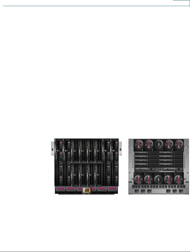
The HP c-Class BladeSystem enclosure represents the next generation of blade-server and bladeswitch integration. Figure 1 shows both a front and back side view of the cabinet. The c-Class enclosure can hold up to 16 half-height servers and up to 8 switch modules. The servers are available with either Intel or AMD processors. HP also offers full-height servers with two Intel processors. Both support dual-core processors. The first two switch bays must contain Ethernet switches because the onboard LAN adapters are routed to those bays. The additional six bays are available for additional Ethernet switches, Fibre Channel switches, InfiniBand switches, or copper or fiber pass-through modules. Each full-height server contains four Gigabit Ethernet interfaces, two running each module in module slots 1 and 2. Full-height servers also have three mezzanine slots for additional I/O connections such as Fibre Channel, InfiniBand, or even more Ethernet switches.
Figure 1. Front and Back Views of HP c-Class BladeSystem Enclosure
The HP c-Class BladeSystem backplane provides power and network connectivity to the blades. The base I/O module slots house a pair of Cisco Catalyst Blade Switch 3020s, which provide a highly available and multihomed environment wherein each server blade is attached through a Gigabit Ethernet port to each Cisco Catalyst Blade Switch 3020. Two Cisco Catalyst Blade Switch 3020s within the blade enclosure connect the blade-server modules to external network devices such as aggregation layer switches. Figures 2 and 3 show the logical connections between the servers, the two internal blade switches, and the outside network.
© 2008 Cisco Systems, Inc. All rights reserved. This document is Cisco Public Information. |
Page 3 of 28 |

Design Guide
Figure 2. Enclosure Interconnections Using Full-Height Servers
Figure 3. Enclosure Interconnections Using Half-Height Servers
© 2008 Cisco Systems, Inc. All rights reserved. This document is Cisco Public Information. |
Page 4 of 28 |

Design Guide
Cisco Catalyst Blade Switch 3020 for HP
This section briefly describes the Cisco Catalyst Blade Switch 3020 for HP and explains how the blade servers within the HP c-Class BladeSystem are physically connected to the switching modules.
The Cisco Catalyst Blade Switch 3020 provides enhanced Layer 2 services (known as Layer 2+ or Intelligent Ethernet switching) to the HP c-Class BladeSystem. The Cisco Catalyst Blade Switch 3020 enhances basic Layer 2 switching by including Cisco proprietary protocols, access control lists (ACLs), and quality of service (QoS) based on Layer 3 information. With Simple Network Management Protocol (SNMP), command-line interface (CLI), or HTTP management options available and a robust set of Cisco IOS® Software switching features, the Cisco Catalyst Blade Switch 3020 naturally integrates into the data center environment. The following features highlight this capacity:
●Loop protection and rapid convergence with support for Per VLAN Spanning Tree Plus (PVST+), IEEE 802.1w, IEEE 802.1s, Bridge Protocol Data Unit (BDPU) Guard, Loop Guard, PortFast, UplinkFast, and Unidirectional Link Detection (UDLD)
●Advanced management protocols, including Cisco Discovery Protocol, VLAN Trunking Protocol (VTP), and Dynamic Trunking Protocol (DTP)
●Port Aggregation Protocol (PAgP) and Link Aggregation Control Protocol (LACP) for link load balancing and high availability
●Support for authentication services, including RADIUS and TACACS+ client support
●Support for protection mechanisms, such as limiting the number of MAC addresses allowed or shutting down the port in response to security violations
Each Ethernet switch provides eight external Ethernet ports for connecting the blade enclosure to the external network. Four Small Form-Factor Pluggable (SFP) ports provide 1000BASE-SX interfaces and are shared with four of the copper Gigabit Ethernet links. Two additional copper Gigabit Ethernet ports are shared with two internal crossover interfaces connecting the pair of switches (labeled X-Crossovers in Figures 2 and 3). All of these ports can be grouped to support the IEEE 802.3ad LACP. Each blade server is connected to the backplane using the available Gigabit Ethernet network interface cards (NICs). The number of NICs on each blade server varies. Each server, whether it is fullor half-height, supports an additional Ethernet interface providing Integrated Lights Out (iLO) support.
Note: The iLO interface supports a management interface that resides on each server blade. For more information about the iLO system, refer to the “Management” section of this guide.
© 2008 Cisco Systems, Inc. All rights reserved. This document is Cisco Public Information. |
Page 5 of 28 |

Design Guide
Cisco Catalyst Blade Switch 3020 Features
This section highlights information about the protocols and features provided by the Cisco Catalyst Blade Switch 3020 that help integrate the HP c-Class BladeSystem enclosure into the Cisco Data Center Network Architecture.
Spanning Tree
The Cisco Catalyst Blade Switch 3020 supports different versions of the Spanning Tree Protocol and associated features, including the following:
●Rapid Spanning Tree Protocol (RSTP), based on IEEE 802.1w
●Multiple Spanning Tree (MST), based on IEEE 802.1s (and includes IEEE 802.1w support)
●PVST+
●Rapid PVST+ (RPVST+)
●Loop Guard
●UDLD
●BPDU Guard
●PortFast
●UplinkFast (Cisco proprietary enhancement for IEEE 802.1d deployments)
●BackboneFast (Cisco proprietary enhancement for IEEE 802.1d deployments)
The IEEE 802.1w protocol is the standard for rapid spanning tree convergence, whereas IEEE 802.1s is the standard for multiple spanning-tree instances. Support for these protocols is essential in a server-farm environment for allowing rapid Layer 2 convergence after a failure occurs in the primary path. The primary benefits of IEEE 802.1w include the following:
●The spanning-tree topology converges quickly after a switch or link failure.
●Convergence is accelerated by a handshake, known as the proposal agreement mechanism.
Note: The user need not enable PortFast, BackboneFast, or UplinkFast if running RSTP.
In terms of convergence, Spanning Tree Protocol algorithms based on IEEE 802.1w are much faster than the traditional Spanning Tree Protocol IEEE 802.1d algorithms. The proposal agreement mechanism allows the Cisco Catalyst Blade Switch 3020 to decide new port roles by exchanging proposals with its neighbors.
With IEEE 802.1w, as with other versions of the Spanning Tree Protocol, BPDUs are sent by default every 2 seconds (called the hello time). If three BPDUs are missed, Spanning Tree Protocol recalculates the topology, a process that takes less than 1 second for IEEE 802.1w.
Because the data center is made of point-to-point links, the only failures are physical failures of the networking devices or links. The IEEE 802.1w protocol can actively confirm that a port can safely transition to forwarding without relying on any timer configuration, meaning that the actual convergence time is less than 1 second.
© 2008 Cisco Systems, Inc. All rights reserved. This document is Cisco Public Information. |
Page 6 of 28 |
Design Guide
A scenario wherein BPDUs are lost may be caused by unidirectional links, which can cause Layer 2 loops. To prevent this problem, use Loop Guard and UDLD. Loop Guard prevents a port from forwarding as a result of missed BPDUs, which might cause a Layer 2 loop that could bring down the network.
UDLD allows devices to monitor the physical configuration of fiberoptic or copper Ethernet cables and detect when a unidirectional link exists. When a unidirectional link is detected, UDLD shuts down the affected port and generates an alert. BPDU Guard prevents a port from being active in a spanning-tree topology as a result of an attack or a misconfigured device connected to the switch port. The port that sees unexpected BPDUs is automatically disabled and must then be manually enabled, giving the network administrator full control over port and switch behavior.
The Cisco Catalyst Blade Switch 3020 supports Per VLAN Spanning Tree (PVST) and a maximum of 128 spanningtree instances. RPVST+ is a combination of Cisco PVST Plus (PVST+) and RSTP, provides the flexibility of one spanning-tree instance per VLAN and the fast convergence benefits of IEEE 802.1w. MST allows the switch to map several VLANs to one spanning-tree instance, reducing the total number of spanning-tree topologies the switch processor must manage. A maximum of 16 MST instances is supported. In addition, MST uses IEEE 802.1w for rapid convergence. MST and RPVST+ create a more predictable and resilient spanning-tree topology, while providing downward compatibility for integration with devices that use IEEE 802.1d and PVST+ protocols.
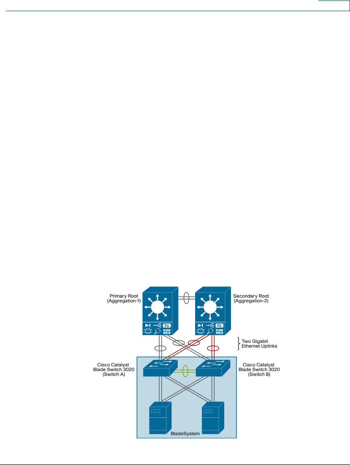
Figure 4 illustrates an example of Spanning Tree Protocol when using two switches in the crossover configuration. Each blade switch is dual homed to each aggregation switch through a 2- port Cisco EtherChannel interface. In this figure the blocked links are indicated in red. In this example, only four of the eight uplinks from each blade switch are used. The network designer can make those EtherChannel uplinks more robust (up to four 4 ports each), or use them to connect other devices such as intrusion detection systems (IDSs) or standalone servers.
Figure 4. Spanning-Tree Example with the HP c-Class Enclosure and Cisco Catalyst Blade Switch 3020s
© 2008 Cisco Systems, Inc. All rights reserved. This document is Cisco Public Information. |
Page 7 of 28 |

Design Guide
Note: The IEEE 802.1w protocol is enabled by default when running spanning tree in RPVST+ or MST mode on the Cisco Catalyst Blade Switch 3020. The Cisco Catalyst Blade Switch 3020 enables PVST+ for VLAN 1 by default.
The Spanning Tree Protocol uses the path cost value to determine the shortest distance to the root bridge. The port path cost value represents the media speed of the link and is configurable on a per-interface basis, including Cisco EtherChannel interfaces. To allow for more granular Spanning Tree Protocol calculations, enable the use of a 32-bit value instead of the default 16-bit value. The longer path cost better reflects changes in the speed of channels and allows the Spanning Tree Protocol to optimize the network in the presence of loops.
Note: The Cisco Catalyst Blade Switch 3020 supports IEEE 802.1t, which allows for spanningtree calculations based on a 32-bit path cost value instead of the default 16 bits. For more information about the standards supported by the Cisco Catalyst Blade Switch 3020, refer to the Cisco Catalyst Blade Switch 3020 Overview document: http://www.cisco.com/go/bladeswitch.
For more information regarding spanning tree and Layer 2 design in the data center, visit: http://www.cisco.com/en/US/solutions/ns340/ns517/ns224/ns304/net_design_guidance0900aecd80 0e4d2e.pdf.
Traffic Monitoring
The Cisco Catalyst Blade Switch 3020 supports the following traffic-monitoring features, which are useful for monitoring blade-enclosure traffic in data center environments:
●Switched Port Analyzer (SPAN)
●Remote SPAN (RSPAN)
SPAN mirrors traffic transmitted or received on source ports or source VLANs to another local switch port. This traffic can be analyzed by connecting a switch or Remote Monitoring (RMON) probe to the destination port of the mirrored traffic. Only traffic that enters or leaves source ports or source VLANs can be monitored using SPAN.
RSPAN facilitates remote monitoring of multiple switches across your network. The traffic for each RSPAN session is carried over a user-specified VLAN that is dedicated to that RSPAN session for all participating switches. The SPAN traffic from the source ports or source VLANs is copied to the RSPAN VLAN. This mirrored traffic is then forwarded over trunk ports to any destination session that is monitoring the RSPAN VLAN.
Figure 5 illustrates the use of RSPAN in a dual-blade switch environment. Here the internal crossconnects can allow the RSPAN traffic to traverse the backplane from one switch to the other. The second switch can either send the SPAN traffic out an uplink port to a local IDS device or pass it up the EtherChannel uplink to the aggregation switch above. Because RSPAN uses its own unique VLAN, it can use ports that may be blocked by other data VLANs.
© 2008 Cisco Systems, Inc. All rights reserved. This document is Cisco Public Information. |
Page 8 of 28 |
Design Guide
Figure 5. RSPAN Example
Link Aggregation Protocols
Cisco Fast EtherChannel interfaces and Gigabit EtherChannel interfaces are logically bundled, and they provide link redundancy and scalable bandwidth between network devices. PAgP and LACP help automatically create these channels by exchanging packets between Ethernet interfaces and negotiating a logical connection. PAgP is a Cisco proprietary protocol that can be run only on Cisco switches or on switches manufactured by vendors that are licensed to support PAgP. LACP is a standard protocol that allows Cisco switches to manage Ethernet channels between any switches that conform to the IEEE 802.3ad protocol. Because the Cisco Catalyst Blade Switch 3020 supports both protocols, you can use either IEEE 802.3ad or PAgP to form port channels between Cisco switches.
For both of these protocols, a switch learns the identity of partners capable of supporting either PAgP or LACP and identifies the capabilities of each interface. The switch dynamically groups similarly configured interfaces into a single, logical link, called a channel or aggregate port. The interface grouping is based on hardware, administrative, and port parameter attributes. For example, PAgP groups interface with the same speed, duplex mode, native VLAN, VLAN range, trunking status, and trunking type. After grouping the links into a port channel, PAgP adds the group to the spanning tree as a single switch port.
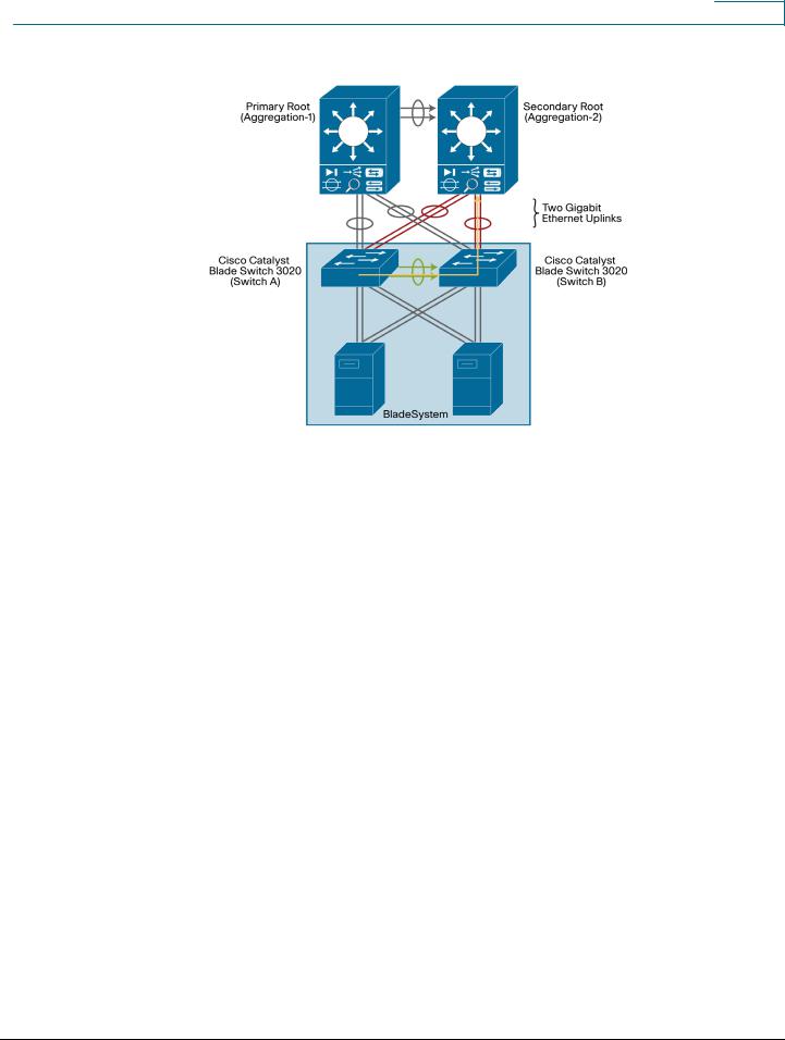
In Figure 6, each blade switch uses an alternative configuration. The switch is no longer dual homed; instead all the ports are put into a single Cisco EtherChannel uplink to the aggregation switch above. This single EtherChannel uplink can use up to the full 8 ports, providing a 2-to-1 cable reduction from the servers. In this configuration, the Spanning Tree Protocol may not be needed because there is no loop in the network if the interconnect ports between the two blade switches are disabled.
© 2008 Cisco Systems, Inc. All rights reserved. This document is Cisco Public Information. |
Page 9 of 28 |
 Loading...