


Digital Tach/Hourmeter with Overspeed Trip Point Installation Instructions for SHD30 and SHD30-45 Models
SHD3-97051N
Revised 05-03 Replaces SHD-96113N Section 20
(00-02-0288)
Please read the following information before installing. A visual inspection for any damage which may have occurred during shipping is recommended. It is your responsibility to have a qualified person install the unit, and make sure it conforms with NEC and local codes.
GENERAL INFORMATION
WARNING
BEFORE BEGINNING INSTALLATION OF THIS MURPHY PRODUCT
Disconnect all electrical power to the machine.
Make sure the machine cannot operate during installation.
Follow all safety warnings of the machine manufacturer.
Read and follow all installation instructions.
C US
Approved for Class I, Division 2, Groups C & D Hazardous Areas
When installed per Murphy Drawing 20-08-0258
Description
The SHD30 and SHD30-45 models are microprocessor-based digital tachometers with hourmeter and overspeed trip point. The overspeed trip point can be connected as either a form “C” relay output or as a normally open SCR output.
In Class I, Div. 2, hazardous locations the SHD30 form “C” relay contact is restricted for use with Murphy non-incendive or intrinsically-safe instruments. In non-hazardous locations the relay contact may be used to switch resistive loads not exceeding 0.5 A @ 30 VDC or 125 VAC.
When connected as a normally open SCR, the output is rated 0.5 A, 350 VDC continuous and can switch up to 3 A @ 350 VDC momentary. The SCR output may be used to switch designated normally open sensor inputs.
Specifications
Power input:
CD ignition: 90 to 350 VDC. 150 µA typical @ 90 VDC; 300 µA @ 350 VDC.
Magnetic Pickup: 5 to 120 Vrms.
325 µA typical @ 5 Vrms, 100 Hz; 450 µA typical @ 5 Vrms, 1 kHz; 1 mA typical @ 5 Vrms, 5 kHz; 2 mA typical @ 5 Vrms, 10 kHz;
15 mW max. @ 5 Vrms, 10 kHz; 2.8 W max. @ 120 Vrms, 10 kHz.
Backup Battery: 2 replaceable, long life Lithium batteries, Panasonic CR2032 or equivalent, 3 V, 220 mAh power.
Operating Temperature: -4° to 158°F (-20° to 70°C). Storage Temperature: -40° to 300°F (-40° to 150°C).
Ignition Frequency Range: 3 to 666 Hz. Magnetic Pickup Frequency Range: 1 to 10 kHz.
Overspeed Output:
Connected to S.C.R. (Silicon Controlled Rectifier) terminals:
0.5 A, 350 VDC continuous.
Connected to Form “C” Relay terminals:
Relay Contact, 0.5 A, 30 VDC, 125 VAC resistive.
Tachometer Accuracy: ±0.5% of the display reading or ±1 RPM whichever is greater.
Hourmeter Range: 0 to 65535 hrs. Hourmeter Accuracy: ±15 minutes per year.
Approvals: CSA approved for Cl. I, Div. 2, Grps. C & D hazardous areas.
Mounting
The SHD30 is designed for installation in panels from 0.032 to 0.125 in. (1 to 3 mm) thick. A round hole, 3-1/8 in. (79 mm) in diameter is needed for mounting. Install the unit within a weatherproof enclosure to protect it from the elements. Keep the unit away from ignition coils and coil leads; a mini-
mum of 12 in. (305 mm) is recommended.
SHD3-97051N 1 of 4
SHD30 Dimensions
5-1/16 in. |
1-9/32 in. |
gasket |
(129 mm) |
(33 mm) |
|
|
4-1/4 in. |
|
|
(108 mm) |
|
|
|
panel |
|
|
Terminal |
|
Mounting Hole |
Blocks |
|
|
|
|
|
2 in. |
|
|
2 in. |
||||||||
|
|
(51 mm) |
|
|
|
|
(51 mm) |
|
|
|
|
|
||
|
|
|
||||||||||||
3-1/8 in. |
|
|
|
|
|
|
|
|
|
|||||
|
|
|
|
|
2 in. |
|||||||||
(79 mm) |
|
|
|
|
|
|||||||||
|
|
|
|
(51 mm) |
||||||||||
diameter |
|
|
|
|
||||||||||
|
|
|
|
|
|
|
|
|
||||||
|
|
|
|
|
|
|
|
|
|
|
|
|
|
|
|
|
|
|
|
|
|
|
|
|
|
|
|||
|
|
|
|
|
|
|
|
|
|
|
|
|||
3/16 in |
|
|
|
|
1-1/2 in. |
|||||||||
|
|
|
|
(38 mm) |
||||||||||
(5 mm) |
|
|
|
|
||||||||||
|
|
|
|
|
|
|
|
|
||||||
diameter, |
|
|
|
|
|
|
|
|
|
|||||
4 places |
|
|
|
|
|
|
|
|
|
|||||
SHD30-45 Dimensions/Mounting
5-13/16 in.
(148 mm )
5-1/16 in.
(129 mm)
4-1/4 in.
5-13/16 in. 
 (108 mm) (148 mm )
Ø6-1/2 in.
Front View
1-5/16 in.
(33 mm )
KEPS Nuts
(3 Supplied)
CD IGN 90-300Vdc TYP:150uA @ 90Vdc; 600uA @ 300Vdc |
MPU 5Vac-120Vac TYP: 325uA @ 5Vac,100Hz; 450uA@ 5Vac 1kHz; 1mA @ 5Vac,5kHz; 2mA @ 5Vac,10kHz; 15mw MAX @ 5Vac,10kHz; 2.8W MAX @ 120Vac, 10kHz |
OUTPUT RELAY = 0.5A, 30Vdc, 125Vdc res SCR = 0.5A, 300Vdc |
MUST BE INSTALLED PER MURPHY DWG. 20-08-0258 INSTALLE CONFORMEMENT MURPHY 20-08-0258 |
|
1/4 in. (6 mm ) dia. holes |
1/2 in. |
|
Ø5-13/64 in. |
(3 places) |
||
(12 mm ) |
|||
|
Rear View |
|
|
|
|
Side View |
TYPICAL WIRING
WARNING: PERFORM THE WIRING INSTALLATION WITH THE POWER SOURCE OFF.
NEVER ROUTE THE SHD30 MODELS OVERSPEED OUTPUT LEADS WITH PRIMARY IGNITION WIRING.
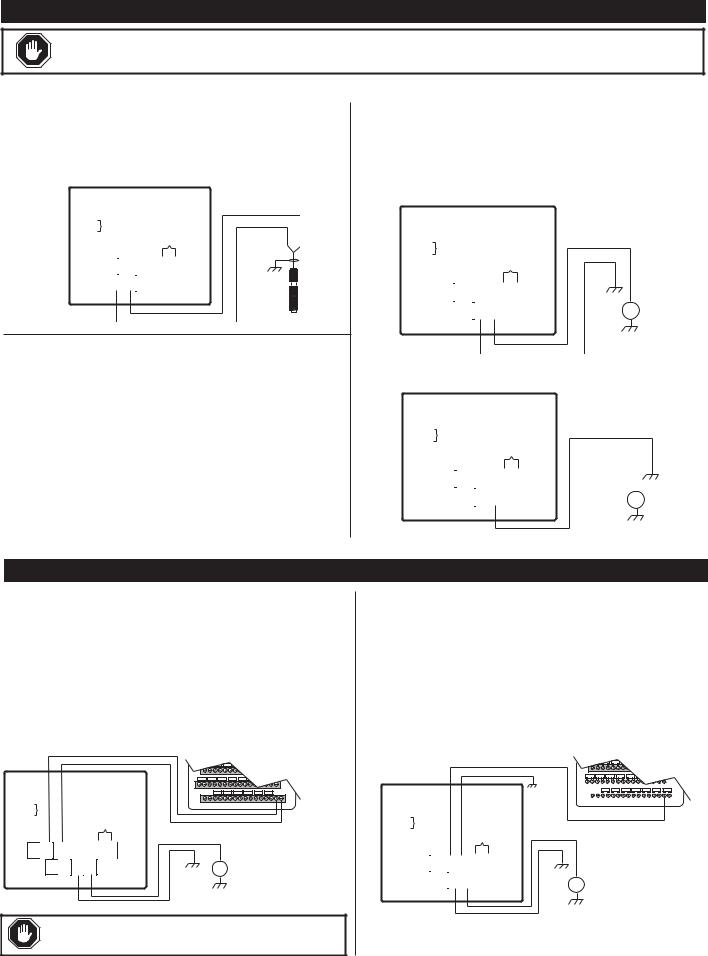
Connecting the Magnetic Pickup
Connect the magnetic pickup cable conductors to the 4-connector terminal strip as shown in Figure 2. Use a two conductor shielded cable between the SHD30 models and the magnetic pickup.
Figure 2: SHD30 models to magnetic pickup typical wiring
|
|
|
|
|
|
|
|
|
TB2 |
|
|
|
SHD30 |
|
||
|
|
|
|
|
|
|
|
|
|
|
|
|
|
|||
|
|
|
|
|
|
|
|
|
1 NO |
|
|
|
|
|
||
TB1 |
|
|
|
|
|
|
|
|
2 C |
|
|
|
|
|
||
|
|
|
|
|
|
|
|
3 NC |
|
|
|
|
|
|||
1 MPU + 5-120Vrms |
|
|
4 +Overspeed SCR |
|
|
|||||||||||
2 MPU – |
|
|
|
|
|
|
5 –Overspeed SCR |
|
|
|||||||
3 NEG 90-300vdc |
|
|
|
|
6 |
|
|
|
|
|
|
|||||
4 POS 90-300vdc |
|
|
|
|
7 Reset Hourmeter |
5-120Vrms |
|
|||||||||
|
N.O. |
C. |
N.C. |
+ |
– |
|
|
|
Shield |
|
||||||
TB2 |
1 |
|
2 |
3 |
4 |
5 |
|
6 |
7 |
|
ground |
|
||||
|
|
|
|
|
||||||||||||
|
|
|
|
|
|
|
|
|
|
|
|
|
|
|
|
|
|
TB1 |
|
1 |
|
2 |
|
3 |
|
4 |
|
|
|
|
|
||
|
|
|
|
|
|
|||||||||||
|
|
|
|
|
|
|||||||||||
|
|
|
+ |
|
– |
|
|
|
|
|
|
|
|
Magnetic Pickup |
|
|
|
|
|
|
|
|
|
|
|
|
|
|
|
|
|
|
|
5 - 120Vrms
Table 1: Output Voltage & Polarity of Common CD Ignitions
Ignition |
Ground |
Peak Output |
Use Figure |
|
MFG & Series |
Polarity |
Voltage |
||
|
||||
Altronic I & V |
Negative |
120 |
3 |
|
|
|
|
|
|
Altronic III |
Negative |
225 |
3 |
|
|
|
|
|
|
Altronic II |
Positive |
350 |
4 |
|
|
|
|
|
|
Bendix S-1800, BLAR |
Negative |
250 |
3 |
|
|
|
|
|
|
Bendix Side-winder |
Positive |
300 |
4 |
|
|
|
|
|
|
Fairbanks Morse SCSA |
Positive |
180 |
4 |
|
|
|
|
|
|
Fairbanks Morse |
Negative |
225 |
3 |
|
3000 & 9000 |
||||
|
|
|
||
American Bosch Magtronic |
Negative |
165 |
3 |
|
|
|
|
|
Connecting to CD Ignition
Before wiring the SHD30 models, determine the output voltage and ground polarity of the ignition. Table 1 (below, left) lists the Peak Output Voltage and Ground Polarity of some common ignitions.
Connect the SHD30 models to a positive or a negative ground CD ignition as shown in Figures 3 or 4.
Figure 3: SHD30 models typical wiring for NEGATIVE ground ignition
|
|
|
|
|
|
|
|
|
TB2 |
|
|
|
SHD30 |
||
|
|
|
|
|
|
|
|
|
|
|
|
|
|||
|
|
|
|
|
|
|
|
|
1 NO |
|
|
|
|
||
TB1 |
|
|
|
|
|
|
|
|
2 C |
|
|
|
|
||
|
|
|
|
|
|
|
|
3 NC |
|
|
|
|
|||
1 MPU + |
|
|
|
|
|
|
4 +Overspeed SCR |
|
|||||||
2 MPU – 5-120Vrms |
|
|
5 –Overspeed SCR |
|
|||||||||||
3 NEG 90-300vdc |
|
|
6 |
|
|
|
|
|
|||||||
4 POS 90-300vdc |
|
|
|
|
7 Reset Hourmeter |
|
|||||||||
|
N.O. |
C. |
N.C. |
+ |
– |
|
|
|
CD Ignition |
||||||
TB2 |
1 |
|
2 |
3 |
4 |
5 |
|
6 |
7 |
|
90-350VDC |
||||
|
|
|
+ |
||||||||||||
|
|
|
|
|
|
|
|
|
|
|
|
|
|
|
|
|
TB1 |
|
1 |
|
2 |
|
3 |
|
4 |
|
|
|
IGN |
||
|
|
|
|
|
|
|
|
|
|
|
|
|
|
|
— |
|
|
|
|
|
|
|
|
|
|
|
|
|
|
|
|
Figure 4: SHD30 models typical wiring for POSITIVE ground ignition
|
|
|
|
|
|
|
|
|
TB2 |
|
|
SHD30 |
|
|
|||
|
|
|
|
|
|
|
|
|
|
|
|
|
|
|
|||
|
|
|
|
|
|
|
|
|
1 NO |
|
|
|
|
|
|
||
TB1 |
|
|
|
|
|
|
|
|
2 C |
|
|
|
|
|
|
||
|
|
|
|
|
|
|
|
3 NC |
|
|
|
|
|
|
|||
1 MPU + 5-120Vrms |
|
|
4 +Overspeed SCR |
|
|
||||||||||||
2 MPU – |
|
|
|
|
|
|
5 –Overspeed SCR |
|
|
||||||||
3 NEG 90-300vdc |
|
|
6 |
|
|
|
|
|
|
|
|||||||
4 POS 90-300vdc |
|
|
+ |
7 Reset Hourmeter |
|
|
|
||||||||||
|
|
|
|
|
|||||||||||||
|
N.O. |
C. |
N.C. |
– |
|
|
|
|
|
|
|||||||
TB2 |
1 |
|
2 |
3 |
4 |
5 |
|
6 |
7 |
|
|
|
— |
||||
|
TB1 |
|
1 |
|
2 |
|
3 |
|
4 |
|
|
|
CD Ignition |
IGN |
|||
|
|
|
|
|
|
|
|
90-350VDC |
|||||||||
|
|
|
|
|
|
|
|
|
|
|
|
|
|
|
|
+ |
|
|
|
|
|
|
|
|
|
|
|
|
|
|
|
|
|
|
|
OVERSPEED OUTPUT WIRING
Connecting the Overspeed Output
A 7-connector terminal strip, on the back of the SHD30 models, is provided for connection of the overspeed output. Terminals C., and N.C. are used for connecting the output as a normally closed relay contact. Terminals (+) and (–) are used for connecting the output as a normally open SCR. Shown in Figure 5 is a typical wiring installation of the SHD30 models normally closed relay output connected to a Murphy MARK III digital annunciator. Figure 6 shows a typical wiring of the
Figure 5: SHD30 models Normally Closed Relay output to MARK III
TB2
|
|
|
1 NO |
|
TB1 |
|
|
2 C |
|
|
|
3 NC |
||
1 MPU + |
5-120Vrms |
|
4 |
+Overspeed SCR |
2 MPU – |
|
|
5 |
–Overspeed SCR |
3 NEG 90-300vdc |
|
6 |
|
|
4 POS 90-300vdc |
|
7 Reset Hourmeter |
||
N O |
C NC |
+ |
– |
|
TB2 1  2 3
2 3  4 5
4 5  6 7
6 7
TB1 1  2 3 4
2 3 4
Back of MARK III
Remove
Jumper
SHD30 To be installed in accor-
+dance with NEC
CD Ignition
IGN 90-350VDC code for Class I,
—Div. 2 Grps. C & D hazardous locations.
WARNING: Overspeed relay contact for use with FWMurphy nonincendive or intrinsically safe products only.
SHD30 models normally open SCR output connected to a Murphy MARK III digital fault annunciator. Figure 7 displays a typical wiring of the SHD30 models normally open SCR output to a Murphy MARK IV annunciator. Figure 8 displays a typical wiring of the SHD30 models normally closed relay output to a Murphy LCDT-NC annunciator. Figure 9 displays a typical wiring of the SHD30 models normally open SCR output to a Murphy LCDT-NO annunciator.
Figure 6: SHD30 models Normally Open SCR output to MARK III
Back of MARK III
 Leave Jumper
in place
|
|
|
|
|
|
|
|
|
|
|
|
|
|
|
|
|
|
|
|
|
|
|
|
|
|
|
|
|
|
|
|
|
|
|
|
|
TB2 |
|
|
||||
|
|
|
|
|
|
|
|
|
|
|
|
|
|
|
|||||||
|
|
|
|
|
|
|
|
|
|
|
|
|
|
|
1 NO |
|
|
||||
TB1 |
|
|
|
|
|
|
|
|
|
|
|
|
|
|
2 C |
|
|||||
|
|
|
|
|
|
|
|
|
|
|
|
|
|
3 NC |
|
||||||
1 MPU + 5-120Vrms |
|
|
|
|
|
4 |
+Overspeed SCR |
|
|||||||||||||
2 MPU – |
|
|
|
|
|
|
|
|
|
|
5 |
–Overspeed SCR |
|
||||||||
3 NEG 90-300vdc |
|
|
|
|
|
|
|
|
|
6 Reset Hourmeter |
|
||||||||||
4 POS 90-300vdc |
|
|
|
|
|
|
|
7 |
|
|
|
|
|
|
|||||||
|
NO |
|
C |
NC |
+ |
|
– |
|
|
|
|
|
|
|
|
|
|||||
TB2 |
1 |
|
2 |
|
3 |
4 |
|
5 |
|
6 |
|
7 |
+ |
|
|
||||||
|
TB1 |
|
1 |
|
|
2 |
|
|
3 |
|
4 |
|
|
|
|
CD Ignition |
|
||||
|
|
|
|
|
|
|
|
|
|
|
|
|
|
|
|
|
|
IGN 90-350VDC |
|
||
—
SHD30 models To be installed in accordance with NEC code for Class I, Div. 2 Grps. C & D hazardous locations.
SHD3-97051N 2 of 4
 Loading...