


OPERATION AND PARTS MANUAL
© COPYRIGHT 2004, MULTIQUIP INC.
MULTIQUIP
MODEL QP-301TH GASOLINE POWERED TRASH PUMP
Revision #4 (10/05/05)
MULTIQUIP INC. |
PARTS DEPARTMENT: |
18910 WILMINGTON AVE. |
800-427-1244 |
CARSON, CALIFORNIA 90746 |
FAX: 800-672-7877 |
310-537-3700 |
SERVICE DEPARTMENT/TECHNICAL ASSISTANCE: |
800-421-1244 |
800-478-1244 |
FAX:310-537-3927 |
FAX:310-631-5032 |
E-mail:mq@multiquip.com • www:multiquip.com
Atlanta • Boise • Dallas • Houston • Newark Montreal, Canada • Manchester, UK
Rio De Janiero, Brazil • Guadalajara, Mexico
PAGE 2 — QP-301TH TRASH PUMP — PARTS MANUAL — REV. #4 (10/05/05)

HERE'S HOW TO GET HELP
PLEASE HAVE THE MODEL AND SERIAL NUMBER ON-HAND WHEN CALLING
PARTS DEPARTMENT
800-427-1244 or 310-537-3700 FAX: 800-672-7877 or 310-637-3284
SERVICE DEPARTMENT
800-421-1244 FAX: 310- 537-4259
TECHNICAL ASSISTANCE
800-478-1244 FAX: 310- 631-5032
WARRANTY DEPARTMENT
888-661-4279, or 310-661-4279 FAX: 310- 537-1173
QP-301TH TRASH PUMP — PARTS MANUAL— REV. 4 (10/05/05 ) — PAGE 3

QP-301TH — TABLE OF CONTENTS
QP-301TH Gasoline
Powered Trash Pump
Here’s How To Get Help ............................................ |
2 |
Table of Contents ...................................................... |
3 |
Parts Ordering Procedures .................................... |
4-5 |
Safety Message Alert Symbols .............................. |
6-7 |
Rules For Safe Operation ...................................... |
8-9 |
Pump Specifications/Dimensions ............................. |
10 |
Engine Specifications ............................................... |
11 |
General Information ................................................. |
12 |
Pump Components .................................................. |
13 |
Basic Engine ............................................................ |
14 |
Pre-Inspection (Engine) ........................................... |
15 |
Pre-Set-up (Pump)................................................... |
16 |
Initial Start-up (Engine) ...................................... |
17-18 |
Maintenance (Pump) ......................................... |
20-21 |
Maintenance (Engine)........................................ |
22-23 |
Preparation for Long-Term Storage ......................... |
24 |
Troubleshooting (Pump)........................................... |
26 |
Troubleshooting (Pump/Engine) .............................. |
27 |
Explanation Of Code In Remarks Column ............... |
28 |
Suggested Spare Parts ............................................ |
29 |
Pump Assy. ........................................................ |
30-33 |
HondaGX240K1PA2Engine
Air Cleaner (Dual) Assembly.............................. |
34-35 |
Camshaft Assembly ........................................... |
36-37 |
Carburetor Assembly ......................................... |
38-39 |
Control Assembly ............................................... |
40-41 |
Crankcase Cover Assembly............................... |
42-43 |
Crankshaft/Balancer Assembly .......................... |
44-45 |
Cylinder Barrel Assembly ................................... |
46-47 |
Cylinder Head Assembly .................................... |
48-49 |
Fan Cover Assembly .......................................... |
50-51 |
Flywheel Assembly ............................................ |
52-53 |
Fuel Tank Assembly ........................................... |
54-55 |
Ignition Coil Assembly ........................................ |
56-57 |
Muffler Assembly ............................................... |
58-59 |
Piston Assembly ................................................. |
60-61 |
Recoil Starter Assembly..................................... |
62-63 |
Gasket Kit Assembly ............................................... |
65 |
Labels ................................................................ |
66-67 |
Terms and Condition Of Sale — Parts .................... |
68 |
Specification and part number are subject to change without notice.
PAGE 4 — QP-301TH TRASH PUMP — PARTS MANUAL — REV. #4 (10/05/05)
PARTS ORDERING PROCEDURES
When ordering parts,
please supply the following information:
Dealer account number
Dealer name and address
Shipping address (if different than billing address)Return fax number
Applicable model number
Quantity, part number and description of each part
Specify preferred method of shipment: |
Note:Unless otherwiseindicatedby customer,all |
||
|
FedEx or UPS Ground |
||
orders are treated as “Standard Orders”, and will |
|||
|
FedEx or UPS Second Day or Third Day |
||
ship within 24 hours.We will make every effort to |
|||
|
FedEx or UPS Next Day |
||
ship “Air Shipments” the same day that the order is |
|||
|
Federal Express Priority One |
received, if prior to 2PM west coast time. “Stock |
|
|
DHL |
Orders” must be so noted on fax or web forms. |
|
Truck
Here’s how to get help...
Please have the model and serial number on hand when calling.
Parts Department |
|
800-427-1244 |
Fax: 800-672-7877 |
310-537-3700 |
Fax: 310-637-3284 |
|
|
Mayco Parts |
|
800-306-2926 |
Fax: 800-672-7877 |
310-537-3700 |
Fax: 310-637-3284 |
|
|
Service Department |
|
800-478-1244 |
Fax: 310-537-4259 |
310-537-3700 |
|
MQ Power Service Department
800-835-2551 Fax: 310-638-8046
310-537-3700
Warranty Department |
|
800-421-1244, Ext. 279 |
Fax: 310-537-1173 |
310-537-3700, Ext. 279 |
|
|
|
Multiquip’s Main Phone Numbers |
|
800-421-1244 |
Fax: 310-537-3927 |
310-537-3700 |
|
Place Your Parts Order Via Web or Fax For Even More Savings!
Extra Discounts!
All parts orders which include complete part numbers and are received by our automated web parts order system, or by fax qualify for the following extra discounts:
Ordered |
Standard |
Stock orders |
via |
orders |
($750 list and above) |
|
|
|
Fax |
3% |
10% |
Web |
5% |
10% |
Special freight allowances when you order 10 or more line items via Web or Fax!**
FedEx Ground Service at no charge for freight
No other allowances on freight shipped by any other carrier.
NOTE:DISCOUNTSARESUBJECTTOCHANGE
MULTIQUIP INC.
18910 WILMINGTON AVENUE POST OFFICE BOX 6254 CARSON, CALIFORNIA 90749 310-537-3700 • 800-421-1244 FAX:310-537-3927
E-MAIL:mq@multiquip.com WWW:multiquip.com
Direct TOLL-FREE access to our Parts Department:
Toll-free nationwide — 800-427-1244
QP-301TH TRASH PUMP — PARTS MANUAL— REV. 4 (10/05/05 ) — PAGE 5

QP-202TH — SAFETY MESSAGE ALERT SYMBOLS
FORYOUR SAFETY AND THE SAFETY OF OTHERS! |
|
HAZARD SYMBOLS |
|
|
|
Safety precautions should be followed at all times when operating this equipment. Failure to read and understand the Safety Messages and Operating Instructions could result in injury to yourself and others.
This Owner's Manual has been developed to provide complete instructions for the safe and efficient operation of the Multiquip Model QP-301TH Trash Pump. Refer to the engine manufacturers instructions for data relative to its safe operation.
Before using these pumps, ensure that the operating individual has read and understands all instructions in this manual.
SAFETY MESSAGE ALERT SYMBOLS
The three (3) Safety Messages shown below will inform you about potential hazards that could injure you or others. The Safety Messages specifically address the level of exposure to the operator, and are preceded by one of three words: DANGER,
WARNING, or CAUTION.
DANGER: You WILL be KILLED or
SERIOUSLY injured if you do not follow
WARNING: You CAN be KILLED or SERIOUSLY injured if you do not follow directions.
CAUTION: You CAN be injured if you do not follow directions.
Potential hazards associated with the QP-301TH Trash Pump operation will be referenced with Hazard Symbols which appear throughout this manual, and will be referenced in conjunction with Safety Message Alert Symbols.
Lethal Exhaust Gases
Engine exhaust gases contain poisonous carbon monoxide. This gas is colorless and odorless, and can cause death if inhaled. NEVER operate this equipment in a confined area or enclosed structure that does not provide ample free flow air.
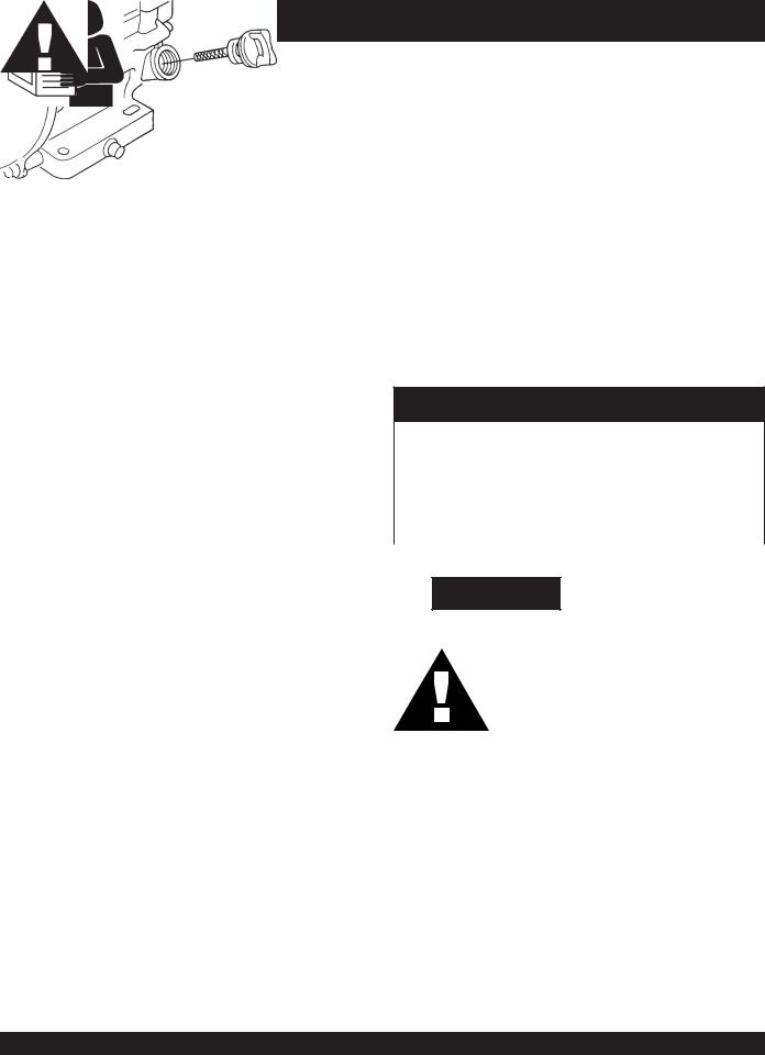
Explosive Fuel
GASOLINE is extremely flammable, and its vapors can cause an explosion if ignited. DO NOT start the engine near spilled fuel or combustible fluids. DO NOT fill the fuel tank while the engine is running or hot. DO NOT overfill tank, since spilled fuel could ignite if it comes into contact with hot engine parts or sparks from the ignition system. Store fuel in approved containers, in well-ventilated areas and away from sparks and flames. NEVER
Burn Hazards
Engine components can generate extreme heat. To prevent burns, DO NOT touch these areas while the engine is running or immediately after operations. Never operate the engine with heat shields or heat guards removed.
Rotating Parts
NEVER operate equipment with covers, or guards removed. Keep fingers, hands, hair and clothing away from all moving parts to prevent injury.
PAGE 6 — QP-301TH TRASH PUMP — PARTS MANUAL — REV. #4 (10/05/05)

QP-202TH — SAFETY MESSAGE ALERT SYMBOLS
Accidental Starting
ALWAYS place the engine ON/OFF switch in the OFF position when the pump is not in use.
Sight and Hearing hazard
Respiratory Hazard
ALWAYS wear approved respiratory protection.
Equipment Damage Messages
ALWAYS wear approved eye and hearing protection.
Other important messages are provided throughout this manual to help prevent damage to your pump, other property, or the surrounding environment.
This pump, other property, or the surrounding environment could be damaged if you do not follow instructions.
QP-301TH TRASH PUMP — PARTS MANUAL— REV. 4 (10/05/05 ) — PAGE 7

DANGER:
Failure to follow instructions in this manual may lead to serious injury or even death! This equipment is to be operated by trained and qualified personnel only! This equipment is for industrial use only.
The following safety guidelines should always be used when operating the trash pump:
GENERAL SAFETY
■DO NOT operate or service this equipment before readingthisentiremanual.
■This equipment should not be operated by persons under 18 years of age.
■NEVER operate this equipment without proper protective clothing, shatterproof glasses, steeltoed boots and other protective devices required by the job.
■NEVER operate this equipment when not feeling well due to fatigue, illness or taking medicine.
■NEVER operate this equipment under the influence or drugs or alcohol.
■Whenever necessary, replace nameplate, operation and safety decals when they become difficult read.
■ALWAYS check the machine for loosened threads or bolts before starting.
■ALWAYS wear proper respiratory (mask) hearing and eye protection equipment when operating the pump.
RULES FOR SAFE OPERATION
■NEVERtouchthehotexhaustmanifold, muffler or cylinder.Allowthese parts to cool before servicing engine or pump.
■HighTemperatures – Allow the engine to cool before adding fuel or performing service and maintenance functions. Contact with hot components can cause serious burns.
■The engine of this pump requires an adequate free flow of cooling air. NEVER! operate the roller in any enclosed or narrow area where free flow of the air is restricted. If the air
flow is restricted it will cause serious damage to the pump or engine and may cause injury to people and property. Remember the pump's engine gives off
DEADLY gases.
■ALWAYS refuel in a well-ventilated area, away from sparks and open flames.
■ALWAYS use extreme caution when working with flammable liquids. When refueling, stop the engine and allow it to cool. DO NOT smoke around or near the machine. Fire or explosion could result from fuel vapors, or if fuel is spilled on a hot engine.
■NEVER operate the pump in an explosive atmosphere or near combustible materials. An explosion or fire could result causing severe bodily harm or even death.
■Topping-off to filler port is dangerous, as it tends to spill fuel.
■Refer to the Engine Owner's Manual for engine technical questions or information.
■NEVER use accessories or attachments, which are not recommended by Multiquip for this equipment. Damage to the equipment and/or injury to user may result.
■Manufacturer does not assume responsibility for any accident due to equipment modifications.
PAGE 8 — QP-301TH TRASH PUMP — PARTS MANUAL — REV. #4 (10/05/05)

■NEVER Run engine without air cleaner. Severe engine damage may occur.
■ALWAYS read, understand, and follow procedures in Operator’s Manual before attempting to operate equipment.
■ALWAYS be sure the operator is familiar with proper safety precautions and operation techniques before using pump.
■ALWAYS store equipment properly when it is not being used. Equipment should be stored in a clean, dry location out of the reach of children.
■NEVER leave the pump unattended, turn off engine when unattended.
■Unauthorized equipment modifications will void all warranties.
■NEVER pump volatile, explosive, flammable or low flash point fluids.These fluids could ignite or explode.
■NEVER operate the pump in an explosive atmosphere.
■Before starting the pump, check that the clean-out cover is securely fasten.
■ALWAYS ensure pump is on level ground before use.
■Become familiar with the components of the pump before operating.
■ALWAYS replace any worn or damaged warning decals.
■NEVER pump corrosive chemicals or water containing toxic substances. These fluids could create serious health and environmental hazards. Contact local authorities for assistance.
■NEVER open the priming plug when pump is hot. Hot water inside could be pressurized much like the radiator of an automobile. Allow pump to cool to the touch before loosening plug.
■NEVER open the pump housing during operation or start the pump with the clean-out cover removed.The rotating impeller inside the pump can cut or sever objects caught in it.
■NEVER block or restrict flow from discharge hose. Remove kinks from discharge line before starting pump. Operation with a blocked discharge line can cause water inside pump to overheat.
■ALWAYS fill the pump casing with water before starting the engine. Failure to maintain water inside the pump housing will cause severe damage to the pump.
■In winter drain water from pump housing to prevent freezing.
RULES FOR SAFE OPERATION
■High Temperatures – Always stop engine and allow the engine to cool before adding fuel, oil or performing service and maintenance functions. Contact with hot components can cause serious burns.
■NEVER disconnect any "emergency or safety devices". These devices are intended for operator safety. Disconnection of these devices can cause severe injury, bodily harm or even death! Disconnection of any of these devices will void all warranties.
Maintenance Safety
■NEVER lubricate components or attempt service on a running machine.
■ALWAYS allow the machine a proper amount of time to cool before servicing.
■Keep the machinery in proper running condition.
■Fix damage to the machine immediately and always replace broken parts, or missing decals.
■Dispose of hazardous waste properly.Examples of potentially hazardous waste are used motor oil, fuel and fuel filters.
■DO NOT use food or plastic containers to dispose of hazardous waste.
■DO NOT pour waste, oil or fuel directly onto the ground, down a drain or into any water source.
Emergencies
■ALWAYS know the location of the nearest fire extinguisher.
■ALWAYS know the location of the nearest first aid kit.
■In emergencies always know the location of the nearest phone or keep a phone on the job site. Also know the phone numbers of the nearest ambulance, doctor and fire department. This information will be invaluable in the case of an emergency.
QP-301TH TRASH PUMP — PARTS MANUAL— REV. 4 (10/05/05 ) — PAGE 9
QP-301TH — SPECIFICATIONS/DIMENSIONS (PUMP)
Table 1. Specifications (Pump)
|
Model |
QP-301TH |
|
|
|
|
|
|
Type |
Trash Pump |
|
|
|
|
|
|
Suction & Discharge Size |
3.00 in. (76 mm.) |
|
|
|
|
|
Pump |
Maximum Pumping |
416 gallons/minute |
|
Capacity |
(1,575 liters/minute) |
||
|
|||
|
|
|
|
|
Max. Solids Diameter |
1.50 in. (38 mm.) |
|
|
|
|
|
|
Max. Lift |
25 ft. (7.62 meters) |
|
|
|
|
|
|
Max. Head |
90 ft. (27.43 meters) |
|
|
|
|
|
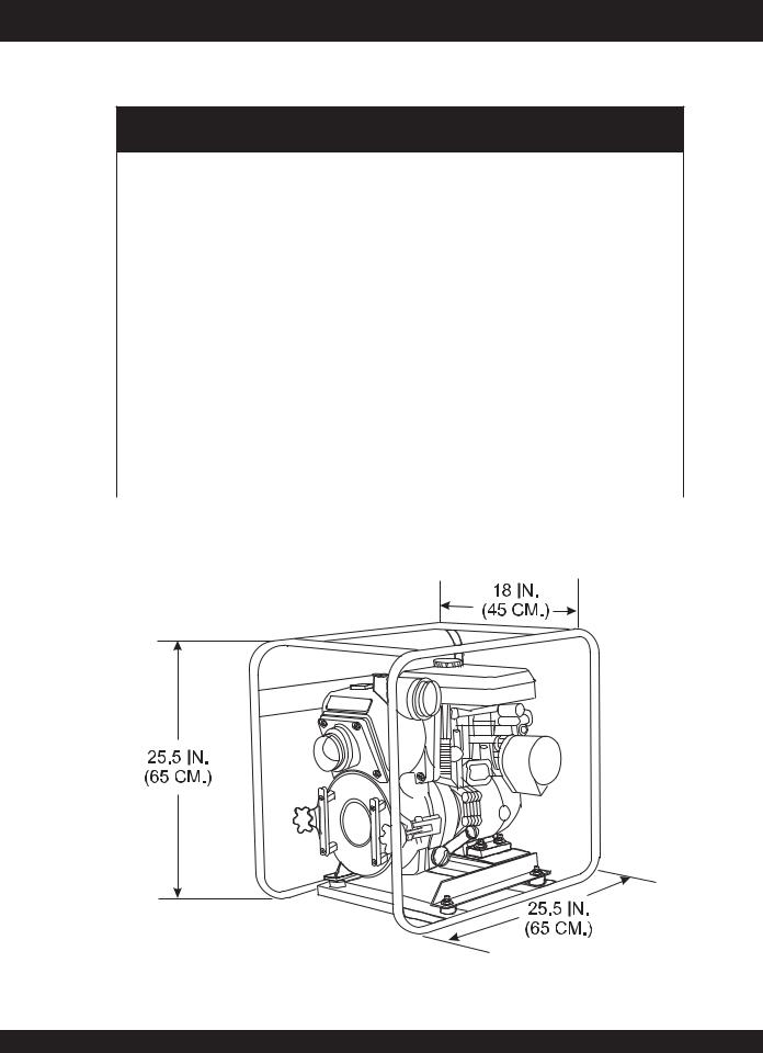
Dimension |
|
25.5 x 18.0 X 25.5 in. |
|
(L x W x H) |
|
(65 X 45 X 65 cm.) |
|
|
|
|
|
Dry Net Weight |
|
150 lbs. (68 Kg.) |
|
|
|
|
Figure 1. QP-202TH Dimensions
PAGE 10 — QP-301TH TRASH PUMP — PARTS MANUAL — REV. #4 (10/05/05)
QP-301TH — SPECIFICATIONS/DIMENSIONS (ENGINE)
Table 2. Specifications (Engine)
|
Model |
HONDA GX240K1PA2 |
|
|
|
|
|
|
|
Air-cooled 4 stroke, Single |
|
|
Type |
Cylinder, OHV, Horizontal |
|
|
|
Shaft Gasoline Engine |
|
|
|
|
|
|
Bore X Stroke |
2.90 in. x 2.30 in. |
|
|
(73 mm x 58 mm) |
||
|
|
||
|
|
|
|
|
Displacement |
14.81 cc. |
|
|
|
|
|
Engine |
Max Output |
8.0 H.P./3600 R.P.M. |
|
|
|
||
Fuel Tank Capacity |
Approx. 1.59 U.S. gallons |
||
|
|||
|
(6.0 liters) |
||
|
|
||
|
|
|
|
|
Fuel |
Unleaded Automobile |
|
|
Gasoline |
||
|
|
||
|
|
|
|
|
Lube Oil Capacity |
1.165 qts. (1.10 liters) |
|
|
|
|
|
|
Speed Control |
Centrifugal Fly-weight Type |
|
|
Method |
||
|
|
||
|
|
|
|
|
Starting Method |
Recoil Start |
|
|
|
|
|
Dimension |
14.0 x 16.9 x 16.1 in. |
||
(L x W x H) |
(355 x 430 x 410 mm) |
||
|
|
|
|
Dry |
55.1 lbs (25 Kg.) |
||
Net Weight |
|||
|
|||
|
|
|
|
QP-301TH TRASH PUMP — PARTS MANUAL— REV. 4 (10/05/05 ) — PAGE 11

QP-301TH — GENERAL INFORMATION
APPLICATION
The QP-301TH Trash Pump is designed to be used for dewatering applications. Both the suction and discharge ports on the QP-301TH trash pump use a 3-inch diameter opening, which allows the pump to pump at a rate of approximately 416 gallons/ minute (gpm) or 1,575 liters/minute (lpm).
Centrifugal or self priming pumps are designed to purge air from the suction line and create a partial vacuum in the pump body. The reduced atmospheric pressure inside the pump allows water to flow through the suction line and into the pump body. The centrifugal force created by the rotating impeller pressurizes the water and expels it from the pump.
Power Plant
This trash pump is powered by an 8.0 horsepower air cooled 4- stroke, single cylinder HONDA GX-240 gasoline engine that incorporates a low "Oil Alert Feature"
Oil Alert Feature
In the event of low oil or no oil, the HONDA GX-240 engine has a built-in oil alarm engine shut-down feature. In the event the oil level is low the engine will automatically shut-down.
Trash Pump
Trash pumps derive their name from their ability to handle a greater amount of debris and solids than standard centrifugal pumps.These pumps generally handle solids up to 1/2 the size of the discharge opening making them less likely to clog. Also trash pumps are capable of handling water with 25% solids by weight.
The advantage of using a trash pump is that it can be quickly and easily disassembled in the field "without tools" and easily cleaned when clogged.
Suction Lift
This pump is intended to be used for dewatering applications and is capable of suction lifts up to 25 feet at sea level. For optimal suction lift performance keep the suction hose or line as short as possible. In general always place the pump as close to the water as possible.
Pump Support
The pump should always be placed on solid stationary ground in a level position.
NEVER place the pump on soft soil. The suction hose or pipe connection should always be checked for tightness and leaks. A small suction leak in the hose or fittings could prevent the pump from priming.
Elevation
Higher elevations will effect the performance of the pump. Due to less atmospheric pressure at higher altitudes, pumps DO NOT have the priming ability that they have at sea level. This is due to the “thinner air” or lack of oxygen at higher altitudes.
A general rule of thumb is that for every 1,000 feet of elevation above sea level a pump will lose one foot of priming ability.
For example, in Flagstaff, Arizona where the elevation is approximately 7,000 feet, the pump would have a suction lift of only 18 feet rather than the 25 feet at sea level. Table 3 shows suction lift at various elevations.
Table 3. Suction Lift at Various Elevations
Altitude
Suction Lift in Feet (Meters)
Feet (Meters)
Sea Level |
10.0 (3.048) |
15.0 |
(4.572) |
20.0 (6.096) |
25.0 (7.620) |
|||
|
|
|
|
|
|
|
|
|
2,000 (610) |
8.80 |
(2.680) |
13.2 |
(4.023) |
17.6 |
(5.364) |
22.0 (6.705) |
|
|
|
|
|
|
|
|
|
|
4,000 (1,219) |
7.80 |
(2.377) |
11.7 |
(3.566) |
15.6 |
(4.754) |
19.5 |
(5.943) |
|
|
|
|
|
|
|
|
|
6,000 (1,829) |
6.90 |
(2.103) |
10.4 |
(3.169) |
13.8 |
(4.206) |
17.3 |
(5.273) |
|
|
|
|
|
|
|
|
|
8,000 (2,438) |
6.20 |
(1.889) |
9.30 (2.834) |
12.4 |
(3.779) |
15.5 |
(4.724) |
|
|
|
|
|
|
|
|
|
|
10,000 (3,048) |
5.70 |
(1.737) |
8.60 (2.621) |
11.4 |
(3.474) |
14.3 |
(4.358) |
|
|
|
|
|
|
|
|
|
|
Table 4 shows percentage drops in performance as elevation increases.
Table 4. Performance Loss at Various
Elevations
Altitude |
Discharge Flow |
Discharge Head |
|
Feet (Meters |
|||
|
|
||
|
|
|
|
Sea Level |
100% |
100% |
|
|
|
|
|
2,000 (610) |
97% |
95% |
|
|
|
|
|
4,000 (1,219) |
95% |
91% |
|
|
|
|
|
6,000 (1,829) |
93% |
87% |
|
|
|
|
|
8,000 (2,438) |
91% |
83% |
|
|
|
|
|
10,000 (3,048) |
88% |
78% |
|
|
|
|
PAGE 12 — QP-301TH TRASH PUMP — PARTS MANUAL — REV. #4 (10/05/05)
QP-301TH — PUMP COMPONENTS
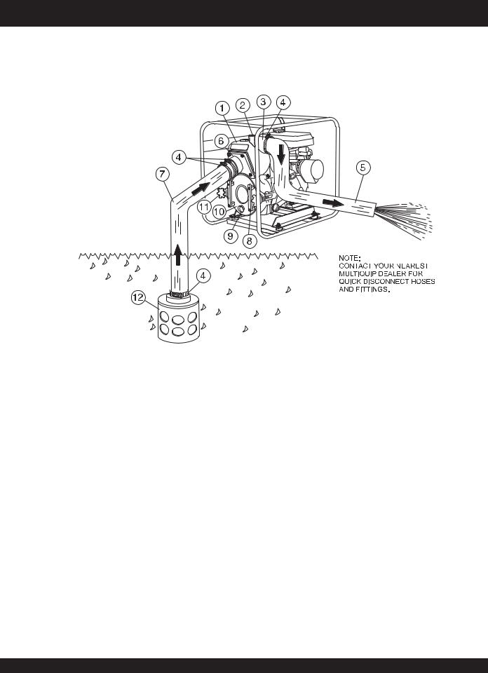
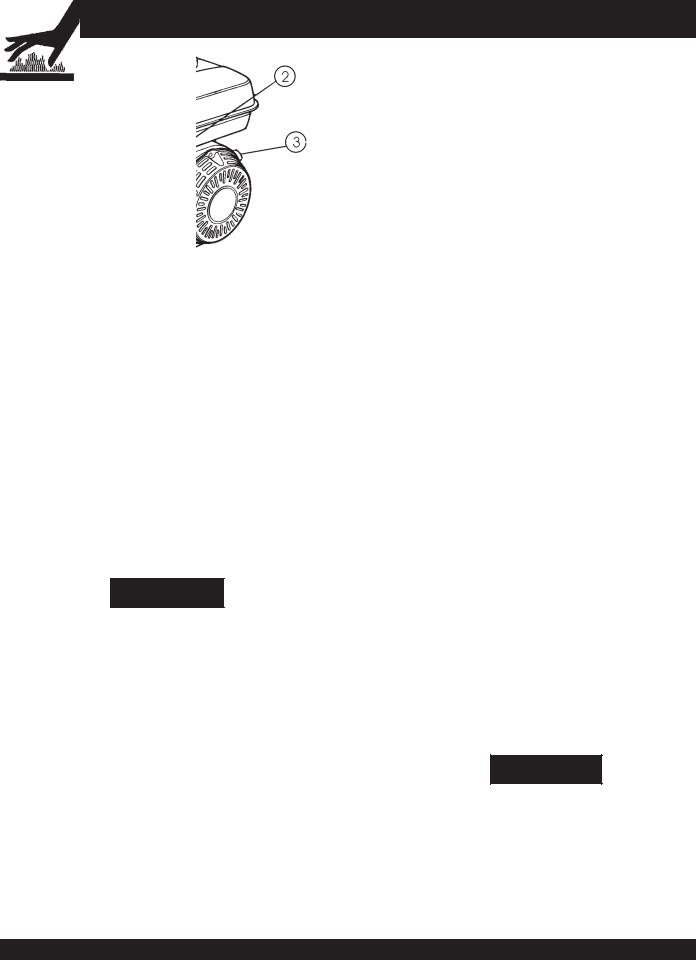
Figure 2 shows a typical application using the QP-301TH Centrifugal Trash pump. Please note that this pump is intended for the removal of clean water and water containing some debris and solids. Maximum size of solids should not exceed 1.5 inch (38 mm) in diameter. DO NOT set strainer on bottom of water bed. Placing the strainer above the water bed will prevent the pump from drawing in excessive amounts of sand and foreign debris.
Figure 2. QP-301TH Pump Application
1. |
Pump – The model QP-301TH is a 3-inch trash pump |
|
used in general de-watering applications. Typical |
|
dewatering applications consist of manholes, septic tanks, |
|
fast and slow seepage ditch water, silt water, mud water |
|
and muck water. |
2. |
Fill Cap – Prior to operation, the pump casing should be |
|
filled with water.Remove this cap to add water to the pump. |
|
After the initial prime, a sufficient amount of water will be |
|
retained in the casing so that the operator will not need to |
|
re-prime later. |
|
If the casing is dry or has insufficient water, the pump will |
|
have difficulty in priming which could lead to premature |
|
mechanical seal wear thus causing damage to the pump. |
3. |
Discharge Port – Connect a 3-inch discharge hose to this |
|
port. |
4. |
Worm Clamp – Used to secure the hose to the inlet and |
|
outlet ports on the pump. Use two clamps to secure the |
|
hose on the inlet side of the pump. |
5. |
Discharge Hose – Connect this flexible rubber hose to |
|
the discharge port on the pump. Make sure that the hose |
|
lays flat and is not kinked. Use only recommended type |
|
discharge hose. Contact Multiquip parts department for |
|
ordering information. |
6. |
Suction Port – Connect a 3-inch inlet hose to this port. |
|
Use two worm clamps to secure the hose. |
7. |
Suction Hose – Connect this flexible rubber hose to the |
|
suction port on the pump. Make sure that the hose lays flat |
|
and is not kinked. Use only recommended type suction |
|
hose. Contact Multiquip parts department for ordering |
|
information |
8. |
Clean-out Cover Handles – To gain access to the pump's |
|
clean-out area, grip both handles, then pull to remove cover. |
|
Make sure both locking knobs have been released before |
|
attempting to remove clean-out cover. |
9. |
Drain Plug – Remove this plug to drain water from the |
|
pump. |
10. Clean-out Cover – Remove cover to gain access to the clean-out area.
11. Locking Knobs– Turn both knobs clockwise to secure clean-out cover, turn counter-clockwise to release cover.
12. Strainer – Always attach a strainer to bottom side of the suction hose to prevent large objects and debris from entering the pump. Strainer should be positioned so that it will remain completely under water.Running the pump with the strainer above water for long periods can damage pump.
QP-301TH TRASH PUMP — PARTS MANUAL— REV. 4 (10/05/05 ) — PAGE 13
QP-301TH — BASIC ENGINE
Figure 3. Engine Controls and Components
6. Choke Lever – Used in the starting of a cold engine, or in cold weather conditions. The choke enriches the fuel mixture.
1. Fuel Filler Cap – Remove this cap to add unleaded gasoline to the fuel tank. Make sure cap is tightened securely. DO NOT over fill.
DANGER
Adding fuel to the tank should be done only when the engine is stopped and has had an opportunity to cool down. In the event of a fuel spill, DO NOT attempt to start the
engine until the fuel residue has been completely wiped up, and the area surrounding the engine is dry.
2. Throttle Lever – Used to adjust engine RPM speed (lever advanced forward SLOW, lever back toward operator
FAST).
3. Engine ON/OFF Switch – ON position permits engine
|
starting, OFF position stops engine operations. |
4. |
Recoil Starter (pull rope) – Manual-starting method. Pull |
|
the starter grip until resistance is felt, then pull briskly and |
|
smoothly. |
5. |
FuelValve Lever – OPEN to let fuel flow, CLOSE to stop |
|
the flow of fuel. |
7. Air Cleaner – Prevents dirt and other debris from entering the fuel system. Remove wing-nut on top of air filter cannister to gain access to filter element.
Operating the engine without an air filter, with a damaged air filter, or a filter in need of replacement will allow dirt to enter the engine, causing rapid engine wear.
8. Spark Plug – Provides spark to the ignition system. Set spark plug gap to 0.6 - 0.7 mm (0.028 - 0.031 inch) Clean spark plug once a week.
9. Muffler – Used to reduce noise and emissions.
WARNING
Enginecomponentscangenerateextremeheat. To prevent burns, DO NOT touch these areas while the engine is running or immediately after operating. NEVER
operate the engine with the muffler removed.
10. Fuel Tank – Holds unleaded gasoline. For additional information refer to engine owner's manual.
PAGE 14 — QP-301TH TRASH PUMP — PARTS MANUAL — REV. #4 (10/05/05)
QP-301TH — PRE-INSPECTION (ENGINE)
CAUTION
NEVERoperate the pump in a confined area or enclosed area structure that does not provide ample free flow of air.
ALWAYS wear approved eye and hearing protection before operating the pump.
Before Starting
1.Read safety instructions at the beginning of manual.
2.Clean the pump, removing dirt and dust, particularly the engine cooling air inlet, carburetor and air cleaner.
3.Check the air filter for dirt and dust. If air filter is dirty, replace air filter with a new one as required.
4.Check carburetor for external dirt and dust. Clean with dry compressed air.
5.Check fastening nuts and bolts for tightness.
Engine Oil Check
1.To check the engine oil level, place the pump on secure level ground with the engine stopped.
2.Remove the filler dipstick from the engine oil filler hole (Figure 4) and wipe clean.
3.Insertandremovethedipstickwithoutscrewingitintothefiller neck. Check the oil level shown on the dipstick.
4.If the oil level is low (Figure 5), fill to the edge of the oil filler hole with the recommended oil type (Table 5).Maximum oil capacity is 1.16 quarts (1.1 liters)
Figure 5. Engine Oil Dipstick (Oil Level)
Table 5. Oil Type
Season |
Temperature |
Oil Type |
|
|
|
Summer |
25°C or Higher |
SAE 10W-30 |
|
|
|
Spring/Fall |
25°C~10°C |
SAE 10W-30/20 |
|
|
|
Winter |
0°C or Lower |
SAE 10W-10 |
|
|
|
Explosive Fuel
DANGER
Motor fuels are highly flammable and can be dangerous if mishandled. DO NOT smoke while refueling. DO NOT attempt to refuel the pump if the engine is hot! or running.
Fuel Check
1.Remove the gasoline cap located on top of fuel tank.
2.Visually inspect to see if the fuel level is low. If fuel is low, replenish with unleaded fuel.
3.When refueling, be sure to use a strainer for filtration. DO NOT top-off fuel. Wipe up any spilled fuel immediately!
Figure 4. Engine Oil Dipstick (Removal)
QP-301TH TRASH PUMP — PARTS MANUAL— REV. 4 (10/05/05 ) — PAGE 15

Before Starting
1.Read safety instructions at the beginning of manual.
2.Place pump as near to water as possible,onafirmflat,levelsurface.
3.Toprimepump,removefillcap(Figure2)andfillpumpcasing with water.If the pump casing is not filled with water before starting, it will not begin pumping.
CAUTION :
Pump casing must be filled with water before using pump. Otherwise pump will not be able to begin pumping.
WARNING :
DO NOT open fill cap if pump is hot! Water inside may be under pressure.
4.Checkforleaksbetweenpumpandengine.Ifwaterisleaking between the pump and engine housing, the seal inside the pumpmaybewornordamaged.Continued operationofthe pumpisnot recommended.Furtherusageofthe pumpunder theseconditionsmaycauseseverewaterdamagetoengine.
Hoses and Clamps
1.Check that all hoses are securely attached to the pump. Make certain suction hose (Figure 2) does not have any air leakage.Tighten hose clamps and couplings as required.
2.Itisrecommendedthat 2 clampsbeusedwhensecuringthe suction hose to the inlet side (suction) of the pump.
3.Remember suction hoses must be rigid enough not to collapse when the pump is in operation.
4.Check that the discharge hose (Figure 2) is not restricted. Place hose so that it lays as straight as it is possible on the ground. Remove any twists or sharp bends from hose which may block the flow of water.
QP-301TH — PRE-SETUP (PUMP)
Suction and discharge hoses are NOTE available from Multiquip. Contact your nearest dealer for more
information.
5.The discharge hose is usually a collapsible (thin-walled) hose, however if a thin-walled discharge hose is not available, a rigid suction hose can be substituted in its place.
6.Make sure the suction strainer (Figure 2) is clean and securely attached to the water end of the suction hose. The strainer is designed to protect the pump by preventing large objects from being pulled into the pump.
CAUTION :
The strainer should be positioned so it will remain completely under water. Running the pump with the strainer above water for long periods can damage the pump.
CAUTION :
DO NOT pump flammable fluids, corrosive chemicals or fluids containing toxic substances. These fluids can create potentially dangerous health and environmental hazards. Contact local authorities for assistance.
CAUTION :
This pump uses a water-cooled mechanical seal to prevent water from seeping into the engine. The passage of water through the pump casing lubricates the seal and prevents it from overheating. NEVER! operate the pump without water in the casing as this will cause damage to the mechanical seal.
PAGE 16 — QP-301TH TRASH PUMP — PARTS MANUAL — REV. #4 (10/05/05)

QP-301TH — INITIAL START-UP (ENGINE)
CAUTION :
3.Place the choke lever (Figure 8) in the "OPEN " position if starting a cold engine.
DO NOT attempt to operate the pump until the Safety, General Information and Inspection sections of this manual have been read and thoroughly understood.
This section is intended to assist the operator with the initial start-up of the trash pump. It is extremely important that this section be read carefully before attempting to use the pump in the field.
Starting the Engine (HONDA engine)
1.Place the engine fuel valve lever (Figure 6) to the "ON" position.
Figure 6. Engine FuelValve Lever (ON Position)
2.Move the throttle lever (Figure 7) away from the slow position, about 1/3 of the way toward the fast position.
Figure 8. Engine Choke Lever (Open)
4.Placethechokelever(Figure 9)inthe"CLOSED"position if starting a warm engine or the temperature is warm.
Figure 9. Engine Choke Lever (Closed)
5.Place the engine ON/OFF switch (Figure 10) in the "ON " position.
Figure 7. Throttle Lever (1/3 Start Position)
Figure 10. Engine ON/OFF Switch (ON Position)
QP-301TH TRASH PUMP — PARTS MANUAL— REV. 4 (10/05/05 ) — PAGE 17

QP-301TH — INITIAL START-UP (ENGINE)
6.Grasp the starter grip (Figure 11) and slowly pull it out.The resistancebecomesthehardestatacertainposition,correspondingtothecompressionpoint.Pullthestartergripbriskly and smoothly for starting.
Figure 11. Starter Grip
7.If the engine has started, slowly return the choke lever (Figure 12 ) to the CLOSED position. If the engine has not started repeat steps 1 through 6.
CAUTION :
ALWAYS run engine at full speed while pumping.
Stopping The Engine
Normal Shutdown
1.Movethethrottlelever tothe IDLEposition (Figure14)and run the engine for three minutes at low speed.
Figure 12. Choke Lever (Closed)
8.Before the pump is placed into operation, run the engine for severalminutes. Checkfor fuelleaks,andnoisesthatwould associate with a lose component.
9.To begin pumping, place the throttle lever (Figure 13) in the "RUN"position.
Figure 13.Throttle Lever (Run)
Figure 14.Throttle Lever (Idle)
2.Aftertheenginecools,turntheengineON/OFFswitchtothe “OFF” position (Figure 15).
Figure 15. Engine ON/OFF Switch (OFF)
3.Place the fuel shut-off lever (Figure 16) in the OFF position.
Figure 16. Fuel Valve Lever (OFF)
Emergency Showdown
1.MovethethrottleleverquicklytotheIDLE position,andplace the engine ON/OFF switch in the OFF position.
PAGE 18 — QP-301TH TRASH PUMP — PARTS MANUAL — REV. #4 (10/05/05)

NOTE PAGE
QP-301TH TRASH PUMP — PARTS MANUAL— REV. 4 (10/05/05 ) — PAGE 19

QP-301TH — MAINTENANCE (PUMP)
Pump Vacuum Test
CAUTION :
DO NOT attempt to start the engine unless the pump has previously been primed with water.Severe pump damage will occur if pump has not been primed.
To perform the pump vacuum test do the following:
1.Remove the pump fill cap (Figure 2), and fill the pump with water.
2.Start the engine as outlined in the initial start-up section, and wait for the pump to begin pumping.
3.As shown in Figure 17 (next page), place a water hose inside the discharge opening of the pump, and turn on the water.This flow of water into the discharge opening will prevent the pump from running dry.
4.Place the Pump Vacuum Tester (P/N 7000030) over the pump suction (inlet) opening (Figure 17) with the vacuum gauge facing upwards. It may be necessary to apply a small amount of water around the rubber seal of the vacuum tester to make a good suction fit.
5.Check and make sure that there are no air leaks between the vacuum tester and the inlet port on the pump. If air leaks are present reseat vacuum tester.
6.Run the pump for a few minutes while monitoring the vacuum gauge. If the gauge indicates a reading between -25 and -20 in. Hg. (inches of mercury) then it can be assumed that the pump is working correctly.
25 in. Hg (inches of mercury) translates into 25 feet of lift at sea level.
7.If the vacuum tester gauge indicates a reading below -20 in. Hg, it can then be assumed that the pump is not functioning correctly, and corrective action needs to be taken.
6.To test the flapper valve, shut down the engine. The vacuum tester should remain attached to the pump suction inlet port by vacuum. This indicates the pump's flapper valve is seating properly to hold water in the suction hose when the engine is stopped.This prevents backflow and allows for faster priming when the engine is restarted.
Adjusting Impeller Clearance
1.If it is necessary to replace impeller or volute, be sure clearance between impeller and volute is adjusted correctly.
2.The impeller should be as close to the volute as possible without rubbing against it. Clearance is adjusted by adding or removing shims from behind the impeller.
3.Check clearance between impeller and insert by slowly pulling starter rope to turn impeller. Remove spark plug to make it easier to turn impeller.
It is important not to remove too many shims or the clearance between the impeller and volute will become too wide and pump performance will be reduced.
Remember as the impeller wear down, additional shims may be required to maintain the clearance between the impeller and insert.
4.Check the impeller every six months for wear, and for clearance between the impeller face and the volute. Also check the shaft seal for wear, as well as the shaft sleeve.
Pump Cleaning
After pumping water containing large amounts of dirt and debris, perform the following:
1.Remove the drain plug from the pump housing (Figure 2) and drain any water left in the pump.
2.Loosen the two locking hand knobs (turn counterclockwise) and remove clean-out cover.
3.Clean and remove dirt, debris from pump casing.Inspect impeller and volute for wear. Replace any damaged or worn parts.
CAUTION :
The impeller may develop sharp edges. Use extreme care when cleaning around the impeller to prevent being cut.
PAGE 20 — QP-301TH TRASH PUMP — PARTS MANUAL — REV. #4 (10/05/05)

QP-301TH — MAINTENANCE (PUMP)
Pressure reading may vary depending on altitude. See Tables 3 and 4 on page 12.
Figure 17. Pump Vacuum Tester
QP-301TH TRASH PUMP — PARTS MANUAL— REV. 4 (10/05/05 ) — PAGE 21
 Loading...