


© COPYRIGHT 2003, MULTIQUIP INC.
OPERATION AND PARTS MANUAL
Reversible Plate
Compactor
 Model
Model
MVH-702DRSC
Revision #1 (12/17/03)
MULTIQUIP INC. |
PARTS DEPARTMENT: |
18910 WILMINGTON AVE. |
800-427-1244 |
CARSON, CALIFORNIA 90746 |
FAX: 800-672-7877 |
310-537-3700 |
SERVICE DEPARTMENT/TECHNICAL ASSISTANCE: |
800-421-1244 |
800-478-1244 |
FAX:310-537-3927 |
FAX:310-631-5032 |
 E-mail:mq@multiquip.com • www:multiquip.com
Atlanta • Boise • Dallas • Houston • Newark Montreal, Canada • Manchester, UK
Rio De Janiero, Brazil • Guadalajara, Mexico
PAGE 2 — MQ-MIKASA MVH-702DRSC COMPACTOR — PARTS & OPERATION MANUAL — REV. #1 (12/17/03)

HERE'S HOW TO GET HELP
PLEASE HAVE THE MODEL AND SERIAL NUMBER ON-HAND WHEN CALLING
MULTIQUIP’SMAINPHONENUMBERS
800-421-1244 FAX: 310-537-3927
310-537-3700
PARTSDEPARTMENT
800-427-1244 |
FAX: 800-672-7877 |
310-537-3700 |
FAX: 310-637-3284 |
MAYCOPARTS |
|
800-306-2926 |
FAX: 800-672-7877 |
310-537-3700 |
FAX: 310-637-3284 |
SERVICEDEPARTMENT
800-478-1244 FAX: 310-537-4259
310-537-3700
MQPOWERSERVICEDEPARTMENT
800-835-2551 FAX: 310-638-8046 310-537-3700
TECHNICALASSISTANCE |
|
|
800-478-1244 |
FAX: 310-631-5032 |
|
WARRANTYDEPARTMENT |
||
800-421-1244, EXT. 279 |
FAX: 310-537-1173 |
|
310-537-3700, EXT. 279 |
|
|
MQ-MIKASA MVH-702DRSC COMPACTOR — PARTS & OPERATION MANUAL — REV. #1 (12/17/03) — PAGE 3

MQ MIKASA MVH-702DRSC-
REVERSIBLE PLATE |
|
COMPACTOR |
|
Proposition 65 Warning .............................................. |
2 |
Here's How To Get Help ............................................. |
3 |
Table Of Contents ...................................................... |
4 |
Parts Ordering Procedures ........................................ |
5 |
Safety Message Alert Symbols .............................. |
6-7 |
Rules for Safe Operation ....................................... |
8-9 |
Operation and Safety Decals ............................. |
10-11 |
Dimensions and Specifications ................................ |
12 |
Features ................................................................... |
13 |
Compactor Components .................................... |
14-15 |
Remote Control Components (Body) ................ |
16-17 |
Remote Control Components (Transmitter)....... |
18-19 |
Before Start-up ........................................................ |
20 |
Battery Charging ...................................................... |
21 |
Operation ........................................................... |
22-23 |
Loading and Unloading ............................................ |
24 |
Maintenance ............................................................ |
25 |
Troubleshooting ................................................. |
26-29 |
Block Diagram .......................................................... |
30 |
Reciever Wiring Diagram ......................................... |
31 |
Valve Control Diagram ............................................. |
32 |
Explanation Of Code In Remarks Column ............... |
34 |
Suggested Spare Parts ............................................ |
35 |
TABLE OF CONTENTS
PARTS ILLUSTRATIONS |
|
Nameplate and Decals....................................... |
36-37 |
Vibrating Plate Assembly .................................. |
38-39 |
Vibrator Assembly .............................................. |
40-41 |
Cover Assembly ................................................. |
42-45 |
Engine Assembly ............................................... |
46-47 |
Hydraulic System Assembly............................... |
48-51 |
Electric Device.................................................... |
52-55 |
Terms and Conditions Of Sale — Parts ................... |
56 |
Specification and part number are subject to change without notice.
PAGE 4 — MQ-MIKASA MVH-702DRSC COMPACTOR — PARTS & OPERATION MANUAL — REV. #1 (12/17/03)
PARTS ORDERING PROCEDURES
When ordering parts,
please supply the following information:
Dealer account number
Dealer name and address
Shipping address (if different than billing address)Return fax number
Applicable model number
Quantity, part number and description of each part
Specify preferred method of shipment: |
Note:Unless otherwise indicated by customer, all |
||
|
FedEx or UPS Ground |
||
orders are treated as “Standard Orders”, and will |
|||
|
FedEx or UPS Second Day or Third Day |
||
ship within 24 hours.We will make every effort to |
|||
|
FedEx or UPS Next Day |
||
ship “Air Shipments” the same day that the order is |
|||
|
Federal Express Priority One |
received, if prior to 2PM west coast time. “Stock |
|
|
DHL |
Orders” must be so noted on fax or web forms. |
|
Truck
Here’s how to get help...
Please have the model and serial number on hand when calling.
Parts Department |
|
800-427-1244 |
Fax: 800-672-7877 |
310-537-3700 |
Fax: 310-637-3284 |
|
|
Mayco Parts |
|
800-306-2926 |
Fax: 800-672-7877 |
310-537-3700 |
Fax: 310-637-3284 |
|
|
Service Department |
|
800-478-1244 |
Fax: 310-537-4259 |
310-537-3700 |
|
MQ Power Service Department
800-835-2551 Fax: 310-638-8046
310-537-3700
Technical Assistance |
|
800-478-1244 |
Fax: 310-631-5032 |
|
|
Warranty Department |
|
800-421-1244, Ext. 279 |
Fax: 310-537-1173 |
310-537-3700, Ext. 279 |
|
Multiquip’s Main Phone Numbers
800-421-1244 Fax: 310-537-3927
310-537-3700
MULTIQUIP INC.
18910 WILMINGTON AVENUE POST OFFICE BOX 6254 CARSON, CALIFORNIA 90749 310-537-3700•800-421-1244 FAX:310-537-3927
E-MAIL:mq@multiquip.com WWW:multiquip.com
Place Your Parts Order Via Web or Fax For Even More Savings!
Extra Discounts!
All parts orders which include complete part numbers and are received by our automated web parts order system, or by fax qualify for the following extra discounts:
Ordered |
Standard |
Stock orders |
via |
orders |
($750 list and above) |
|
|
|
Fax |
3% |
10% |
Web |
5% |
10% |
Special freight allowances when you order 10 or more line items via Web or Fax!**
FedEx Ground Service at no charge for freight
No other allowances on freight shipped by any other carrier.
NOTE:DISCOUNTSARESUBJECTTOCHANGE
Direct TOLL-FREE access to our Parts Department:
Toll-free nationwide — 800-427-1244
MQ-MIKASA MVH-702DRSC COMPACTOR — PARTS & OPERATION MANUAL — REV. #1 (12/17/03) — PAGE 5
MVH-702DRSC — SAFETY MESSAGE ALERT SYMBOLS
FORYOUR SAFETY AND THE SAFETY OF OTHERS!
Safety precautions should be followed at all times when operating this equipment. Failure to read and understand the Safety Messages and Operating Instructions could result in injury to yourself and others.
This Owner's Manual has been developed to provide complete instructions for the safe and efficient operation of the Multiquip Model MVH-702DRSC Reversible Plate Compactor. Refer to the engine manufacturer’s instructions
for data relative to its safe operation.
Before using this compactor, ensure that the operating individual has read and understands all instructions in this manual.
SAFETY MESSAGE ALERT SYMBOLS
The three (3) Safety Messages shown below will inform you about potential hazards that could injure you or others. The Safety Messages specifically address the level of exposure to the operator, and are preceded by one of three words: DANGER,
WARNING, or CAUTION.
DANGER: You WILL be KILLED or SERIOUSLY injured if you do not follow directions.
WARNING: You CAN be KILLED or SERIOUSLY injured if you do not follow directions.
CAUTION: You CAN be injured if you do not follow directions.
Potential hazards associated with this compactor operation will be referenced with Hazard Symbols which appear throughout this manual, and will be referenced in conjunction with Safety Message Alert Symbols.
HAZARD SYMBOLS
Lethal Exhaust Gases
Engine exhaust gases contain poisonous carbon monoxide. This gas is colorless and odorless, and can cause death if inhaled. NEVER operate this equipment in a confined area or enclosed structure that does not provide ample free flow air.
Explosive Fuel
GASOLINE is extremely flammable, and its vapors can cause an explosion if ignited. DO NOT start the engine near spilled fuel or combustible fluids. DO NOT fill the fuel tank while the engine is running or hot. DO NOT overfill tank, since spilled fuel could ignite if it comes into contact with hot engine parts or sparks from the ignition system. Store fuel in approved containers, in well-ventilated areas and away from sparks and flames. NEVER use fuel as a cleaning agent.
Burn Hazards
Engine components can generate extreme heat. To prevent burns, DO NOT touch these areas while the engine is running or immediately after operations. Never operate the engine with heat shields or heat guards removed.
Rotating Parts
NEVER operate equipment with covers, or guards removed. Keep fingers, hands, hair and clothing away from all moving parts to prevent injury.
PAGE 6 — MQ-MIKASA MVH-702DRSC COMPACTOR — PARTS & OPERATION MANUAL — REV. #1 (12/17/03)

MVH-702DRSC — SAFETY MESSAGE ALERT SYMBOLS
Accidental Starting
ALWAYS place the engine ON/OFF switch in the OFF position, when the compactor is not in use.
Sight and Hearing hazard
Respiratory Hazard
ALWAYS wear approved respiratory protection.
Equipment Damage Messages
ALWAYS wear approved eye and hearing protection.
Other important messages are provided throughout this manual to help prevent damage to your compactor, other property, or the surrounding environment.
This compactor, other property, or the surrounding environment could be damaged if you do not follow instructions.
MQ-MIKASA MVH-702DRSC COMPACTOR — PARTS & OPERATION MANUAL — REV. #1 (12/17/03) — PAGE 7

MVH-702DRSC — RULES FOR SAFE OPERATION
CAUTION:
Failure to follow instructions in this manual may lead to serious injury or even death! This equipment is to be operated by trained and qualified personnel only! This equipment is for industrial use only.
The following safety guidelines should always be used when operating the MIKASA MVH-702DRSC Reversible Plate Compactor:
GENERAL SAFETY
■DO NOT operate or service this equipment before readingthisentiremanual.
■This equipment should not be operated by persons under 18 years of age.
■NEVER operate this equipment without proper protective clothing, shatterproof glasses, steeltoed boots and other protective devices required by the job. ALWAYS wear slip resistant safety shoes or boots.
■NEVERoperatethisequipmentwhennotfeeling well due to fatigue, illness or taking medicine.
■NEVER operate this equipment under the influence or drugs or alcohol.
■NEVER use accessories or attachments, which are not recommended by Multiquip for this equipment. Damage to the equipment and/or injury to user may result.
■Manufacturer does not assume responsibility for any accident due to equipment modifications.
■Whenever necessary, replace nameplate, operation and safety decals when they become difficult read.
■ALWAYS wear proper respiratory (mask), hearing and eye protection equipment when operating the compactor.
■NEVERtouchthehotexhaustmanifold, muffler or cylinder.Allow these parts to cool before servicing engine or
■HighTemperatures – Allow the engine to cool before adding fuel or performing service and maintenance functions. Contact with hot components can cause serious burns.
■The engine of this compactor requires an adequate free flow of cooling air. NEVER operate the compactor in any enclosed
or narrow area where free flow of the air is restricted. If the air flow is restricted it will cause serious damage to the compactor or engine and may cause injury to people and property. Remember the compactor's enginegivesoff
DEADLY gases.
■ALWAYS refuel in a well-ventilated area, away from sparks and open flames.
■ALWAYS use extreme caution when working with flammable liquids. When refueling, stop the engine and allow it to cool. DO NOT smoke around or near the machine. Fire or explosion could result from fuel vapors, or if fuel is spilled on a hot engine.
■NEVER operate the compactor in an explosive atmosphere or near combustible materials. An explosion or fire could result causing severe bodily harm or even death.
■ Topping-off to filler port is dangerous, as |
it tends to |
spill fuel. |
|
■ALWAYS stored the compactor in a clean, dry location out of the reach of children.
■NEVER Run engine without air cleaner. Severe engine damage may occur.
■NEVER leave the compactor unattended, turn off engine.
■CAUTION must always be observed while servicing this compactor. Rotating parts can cause injury if contacted.
■DO NOT leave compactor with engine running. Use chock blocks if parking compactor on a grade.
PAGE 8 — MQ-MIKASA MVH-702DRSC COMPACTOR — PARTS & OPERATION MANUAL — REV. #1 (12/17/03)

MVH-702DRSC — RULES FOR SAFE OPERATION
■ALWAYS use extreme care when operating near obstructions, on slippery surfaces, grades and side slopes.
■When reversing, particularly on the edges and banks of ditches, as well as in front of obstacles, the operator must stay in a standing position at a safe distance from the machine.
■When operating near any house/building or pipelines, always check the effect of machine vibration. Stop the work if necessary.
■Unauthorized equipment modifications will void all warranties.
■Refer to the Engine Owner's Manual for engine technical questions or information.
■DO NOT operate the compactor with the front or rear cover open.
■Replace any worn or damaged compactor components immediately.
■ALWAYS turn the engine OFF before performing must be before performing maintenance.
■ALWAYS make sure compactor is correctly secured to the trailer.Check all supports attaching the compactor to the trailer and make sure they are tight.
■ALWAYS keep the machine away from workers and obstacles. Also keep the immediate area free of bystanders.
■ALWAYS check the machine for loosened threads or bolts before starting.
■ALWAYS read, understand, and follow procedures in Operator’s Manual before attempting to operate equipment.
■ALWAYS be sure the operator is familiar with proper safety precautions and operations techniques before using compactor.
■A copy of this manual shall accompany the compactor at all times.
■DO NOT use worn out hoses or couplings; inspect daily.
■High Temperatures – Always stop engine and allow the engine to cool before adding fuel, oil or performing service and maintenance functions. Contact with hot components can cause serious burns.
■NEVER disconnect any "emergency or safety devices". These devices are intended for operator safety. Disconnection of these devices can cause severe injury, bodily harm or even death! Disconnection of any of these devices will void all warranties.
Emergencies
■ALWAYS know the location of the nearest fire extinguisher and first aid kit. Know the location of the nearest telephone. Also know the phone numbers of the nearest ambulance, doctor and fire department. This information will be invaluable in case of an emergency.
Maintenance Safety
■NEVER lubricate components or attempt service on a running machine.
■ALWAYS allow the machine a proper amount of time to cool before servicing.
■Keep the machinery in proper running condition.
■Fix damage to the machine immediately and always replace broken parts.
■Dispose of hazardous waste properly.Examples of potentially hazardous waste are used motor oil, fuel and fuel filters.
■DO NOT use food or plastic containers to dispose of hazardous waste.
■DO NOT pour waste, oil or fuel directly onto the ground, down a drain or into any water source.
Lifting
■The compactor has an operating weight of approximately 1600 lbs. (728 Kg). Use lifting equipment capable of lifting this weight.
■Make sure the engine is off before lifting the machine.
■Use reliable cable in lifting the machine.
■Lift upright with sufficient bearing capacity to prevent machine from tilting or slipping.
■When lifting, keep the machine away from workers and animals.
MQ-MIKASA MVH-702DRSC COMPACTOR — PARTS & OPERATION MANUAL — REV. #1 (12/17/03) — PAGE 9
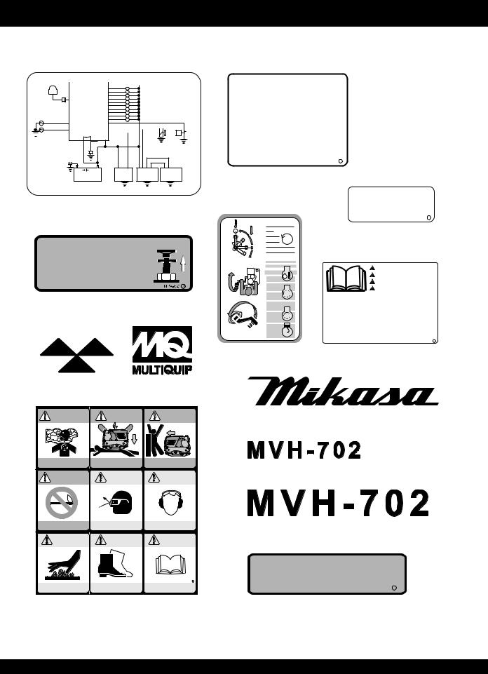
MVH-702DRSC — OPERATION AND SAFETY DECALS
Figure 1 displays the operation and safety decals as they appear on the compactor. Should any of these decals become damaged or unreadable, contact the Multiquip Parts Department for a replacement set.
I.R RECIEVER UNIT
THERMAL SENSOR 1
 THERMAL SENSOR 2
CONTROL BOX |
|
|
|
|
|
|
|
|
|
|
|
|
HOUR METER |
|
|
|
H |
|
HOUR METER |
||||||
ABNORMAL COMMUNICATION LAMP |
|
|
X |
ABNORMAL COMMUNICATION LAMP |
||||||||
OVERHEAT LAMP |
|
|
X |
OVERHEAT LAMP |
||||||||
ABNORMAL OIL PRESSURE LAMP |
|
|
X |
ABNORMAL OIL PRESSURE LAMP |
||||||||
REGULATOR ABNORMALITY LAMP |
|
|
X |
REGULATOR ABNORMALITY LAMP |
||||||||
OPERATION LAMP |
|
|
X |
OPERATION LAMP |
||||||||
LEFT FORWARD SOLENOID |
|
|
LF |
LEFT FORWARD SOLENOID |
||||||||
LEFT BACK SOLENOID |
|
|
LB |
LEFT BACK SOLENOID |
||||||||
RIGHT FORWARD SOLENOID |
|
|
RF |
RIGHT FORWARD SOLENOID |
||||||||
RIGHT BACK SOLENOID |
|
|
RB |
RIGHT BACK SOLENOID |
||||||||
VIBRATION SOLENOID |
|
|
VIB |
VIBRATION SOLENOID |
||||||||
OIL PRESSURE SWITCH |
|
|
|
|
|
|
|
|
|
|
|
|
MAGNET VALVE OUTPUT |
|
|
|
|
|
|
|
|
|
|
|
|
REGULATOR ABNORMALITY INPUT |
|
|
|
|
|
|
|
|
|
|
P |
|
STARTER OUTPUT |
|
|
|
|
|
|
|
|
|
|
||
|
|
|
|
|
|
|||||||
GND |
+12V |
|
|
|
|
|
MAGNET |
OIL PRESSURE |
|
|
|
VALVE |
SWITCH |
|
- |
+ |
|
|
|
BATTERY |
STARTER |
REGULATOR |
GENERATOR |
|
 CAUTION
1)Transmitter must be fully charged before using.
2)Charge Transmitter for initial use and after prolonged storage.
3)Solar collectors only maintain battery charge.
4)See Operations Manual for charging details.
Set Main switch on Control box to “OFF” position to avoid battery drain
NPA-951 J
P/N:TBD
|
Shell Tellus Oil |
P/N: 920109700 |
45 |
NPA-748 J
 FOR EMERGENCY
Pull the knob untill engine stops completely
P/N: 920109800
STOP
995.133.4
P/N: 920108810
CAUTION
ATTENZIONE
ATENÇAÕ
PRECAUCION
*Read operator’s manual carefully before use.
*Lire le manuel attentivement avant utilisation.
*Bitte lesen Sie vor Inbetriebnahme der Maschine die Bedienungsanleitung sorgafältig durch.
*Prima dell’ uso leggere attentamente il manuale.
*Lee com atenÇão o manual de instruÇões antes de usar.
*Leer detenidamente el manual de instrucciones antes de usar la maquina.
NPA-769 J
P/N: TBD |
P/N: 920108350 |
CARSON, CALIF.
P/N: 920100920 P/N: 920209020
DANGER |
DANGER |
DANGER |
FUEL |
FUEL |
FUEL |
P/N: 920101580
Operate only in well- |
Do not stand next to |
Use caution while |
ventilated area |
machine while lifting |
operating |
DANGER |
WARNING |
WARNING |
FUEL |
DUST |
NOISE |
Fire Risk Wear eye protection Wear ear protection
WARNING |
WARNING |
WARNING |
DUST |
DUST |
NOISE |
|
|
NPA-923 J |
Operate only in well- |
Do not stand next to |
Use caution while |
ventilated area |
machine while lifting |
operating |
P/N: 920109770
P/N: 920109550
P/N: 920109840
MAIN SWITCH
NPA-930 J
P/N: 920109750
Figure 1a. Operation and Safety Decals
PAGE 10 — MQ-MIKASA MVH-702DRSC COMPACTOR — PARTS & OPERATION MANUAL — REV. #1 (12/17/03)
MVH-702DRSC — OPERATION AND SAFETY DECALS
Figure 1 displays the operation and safety decals as they appear on the compactor. Should any of these decals become damaged or unreadable, contact the Multiquip Parts Department for a replacement set.
 CAUTION
1.Read owner’s instruction manual before operating or servicing this machine.
2.The machine consists of the engine located in front, and the aluminum hydraulic oil tank in rear. The operator should stand 7 feet (2m) away from to operate the machine. When operating the plate while standing in front of the machine please note that the travel controls will function in the opposite direction.
3.The remote control operation is restricted to a narrower area the further you are from the machine. The transmitter should be pointed more directly toward the machine.
4.In case for emergency such as the failure of the transmitter, pull Emergency Stop Lever located on the machine immediately and wait until the engine stops completely.
5.The remote control operation is not available in the following cases and the vibration stops automatically in operation.
The case A: Operator stands within approx. 3 feet (1m) distance, to operate machine. The case B: Operator stands approx. 60 feet (10m) or father from the machine, to operate [approx. 40 feet (12m) far in the direct rays of the sun]. These distances may vary.
The Case C: Operator stops sending control signals for more than one second.
6.In the case that several machines are operating in the same area, each machine should be transmitting on a different infra-red channel.
7.A flashing light of the transmitter blinks during normal operation. A voltage drop of the transmitter battery will cause the flashing light to alternate between on and off.
8.Hang-up the transmitter away from the machine for safety sake.
9.In operation with remote cable, do not pull out the cable strongly or run over it with the machine.
10.Keep the transmitter away from the machine for safety sake.
11.To avoid excessive dust contamination of air cleaner, water may be used for dust control in high dust areas.
12.To finish operation, be sure to switch off the main switch on receiver and press the emergency stop button on transmitter.
13.When storing outside, keep the machine covered from the rain and always keep the transmitter indoors.
NPA-919 J
P/N: 920109780
OPERATIONAL CAUTION
1.Starting engine by electric starter
a.Ensure that the start switch is set at Cell-Start position and move main switch to “ON” position.
b.Do not run starter longer than 10 seconds to avoid overheating.
c.Warmup the engine without load for 3 to 5 minutes.
2.Manually starting engine
a.Ensure that the start switch is set at Crank-Start position, and move main switch to “ON” position.
b.Warm up the engine without load for 3 to 5 minutes.
3.To stop engine
a.Move stop switch to “OFF” position after running at idle for 3 to 5 minutes. B. If engine does not stop properly, push the throttle lever next to the oil filter until it comes to a completely stop, which takes approximately 15 seconds.
c.After operation is completed, move both control switches of machine and controller to the “OFF” position
MONITOR LAMP LIST
No. |
Contents |
No. |
Contents |
1 |
LEFT FORWARD |
7 |
STOP |
2 |
LEFT BACK |
8 |
RECEPTION |
3 |
RIGHT FORWARD |
9 |
CHARGE |
4 |
RIGHT BACK |
10 |
OIL PRESSURE |
5 |
START |
11 |
OVERHEAT |
6 |
VIBRATION |
12 |
SWITCH OFF |
NPA-903 J
P/N: 920109710
C A U T I O N
NR. (RECIEVING FAILURE LIGHT)
The remote control operation is restricted to a narrower area the further you are from the machine. If the operative signals do not reach the plate properly, RECEIVING FAILURE LIGHT is immediately on and will stop the plate vibration automatically (the engine will continue running)
OP. (OIL PRESSURE (ENGINE) FAILURE LIGHT)
If the engine oil is low or the hydraulic oil pump is out of order, OIL PRESSURE FAILURE LIGHT is on and will stop the engine automatically
RE.(REGULATOR FAILURE LIGHT)
Tif the alternator and regulator in engine are out of order, REGULATOR FAILURE LIGHT is on, but the machine is operative. Be sure to check them after operation
OH.(E/G OVERHEAT LIGHT)
If the engine is continuously overloaded or if the air element is plugged due to excessive dust, the machine E/G OVERHEAT LIGHT will light to notify of an engine overheat. To correct, run the machine without vibration about 5 minutes or stop the engine for cleaning air element. If this is not done the machine will stop vibration automatically a n d c o n t i n u e t o r u n w i t h o u t v i b r a t i o n f o r c o o l i n g t h e e n g i n e . The vibrator will not start again until the engine temperature reaches and acceptable level.
P/N:920109790
OPERATIONAL CAUTION
1.Operating multiple machines on a jobsite
Each machine has a remote control channel setting, both in the plate and in the transmitter. To assure proper operation the channel numbers must match between the machine and the transmitter. When using more than one machine at the same jobsite, each machine and accompanying transmitter must be set a t a different channel number than the other machines but each machine should still match its transmitter.
2.Air Filter service
a.If air cleaner element is clogged, the over-heat lamp will come on.
b.Clean up or replace the cleaner element immediately. Otherwise, machine vibration will stop automatically and will not start its vibration again until the engine has enough time to cool down.
SIGNAL |
|
|
|
BATTERY |
|
|
|
|
CHARGE |
|
|
CHANNEL |
|
NPA-908 |
K |
|
|
|
INLET |
|
|||
|
|
|
|
|
|
|
|
|
|
|
NPA-907 K |
P/N: 920109720 |
|
|
|
|
|
MVH-RCNPA-908 K |
|
||||
P/N: 920209080 |
|
|
|
|
|
|
|
|
|
HYDRAULIC |
|
DIESEL |
|
|
|
OIL ONLY |
|
|
|
|
|
NPA-928 J |
|
FUEL |
|
P/N: 920109810 |
|||
|
|
|
OPEN |
||
ONLY |
|
|
|
||
NPA-927 J |
|
|
|
|
|
|
|
|
|
|
NPA-922 J |
P/N: 920102710 |
|
P/N: 920209310 |
|||
|
|
||||
MAIN SWITCH |
|
|
|
||
|
NPA-904 J |
|
|
|
|
P/N: 920109750 |
|
|
|
|
|
|
VIBRATION |
|
NP -3 |
J |
|
SIGNAL BATTERY CHARGE |
SWITCH |
|
|||
|
|
|
A 33 |
|
|
|
|
ON |
|
P/N: 920203330 |
|
|
|
OFF |
|
||
MAIN SWITCH |
|
|
|
|
|
EMERGENCY STOP |
|
|
|
|
|
|
ENGINE |
|
|
|
|
|
SWITCH |
|
SAE 10W-40 |
||
ON |
|
|
|
||
OFF |
START |
STOP |
|
Motor Oil |
|
|
|
|
|
|
NPA-748 J |
MVH-906
P/N: 920209230
P/N: 920109730
OH RE OPNPA-925 J NR
P/N: 920209250
Figure 1b. Operation and Safety Decals
MQ-MIKASA MVH-702DRSC COMPACTOR — PARTS & OPERATION MANUAL — REV. #1 (12/17/03) — PAGE 11
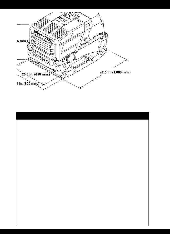
MVH-702DRSC — DIMENSIONS AND SPECIFICATIONS
Figure 2. MVH-702DRSC Compactor Dimensions
Table 1. MVH-702DRSC Compactor Specifications
|
|
With Regular |
With 3-inch |
|
|
|
Plate |
Extension Plate |
|
|
|
|
|
|
|
Overall Length |
42.5 in. (1,080 mm) |
||
|
|
|
|
|
Body Dimensions |
Overall Width |
26.8 in. |
31.5 in. |
|
|
(680 mm |
(800 mm |
||
|
|
|||
|
|
|
|
|
|
Overall Height |
31.3 in. (795 mm) |
||
|
|
|
|
|
|
Width |
25.6 in. |
31.5 in. |
|
Plate Size |
(650 mm) |
(800 mm) |
||
|
||||
|
|
|
||
|
|
|
|
|
|
Length |
43.3 in. (1,100 mm) |
||
|
|
|
|
|
Operating Weight |
|
1477 lbs. |
1543 lbs. |
|
|
(670 kg.) |
(700 kg.) |
||
|
|
|||
|
|
|
|
|
|
VPM |
3,120 rpm (52 Hz) |
||
Performance |
|
|
|
|
Centrifugal Force |
18,000 lbs./blow(80 KN) |
|||
|
||||
|
|
|
|
|
|
Travel Speed |
0 - 92 ft/min (0 28 m/min) |
||
|
|
|
|
|
|
Model |
FARYMANN 43F |
||
|
|
|
|
|
|
Maximum Output |
15.5 PS (11.4 KW) |
||
Engine |
|
|
|
|
Fuel |
DIESEL 2 gallons (7.5 liters) |
|||
|
||||
|
|
|
|
|
|
Start |
Electric Start |
||
|
(crank handle for emergency) |
|||
|
|
|||
|
|
|
|
|
PAGE 12 — MQ-MIKASA MVH-702DRSC COMPACTOR — PARTS & OPERATION MANUAL — REV. #1 (12/17/03)

MVH-702DRSC — FEATURES
The Mikasa Model MVH-702DRSC is a Reversible Plate Compactor which operates by infra-red remote control with forward-reverse motion, steering, and stepless speed control by single-lever joystick.
Features include:
Machine operation is automatically stopped (vibration remains on) by releasing the single-lever joystick.
Monitoring lamps for self-diagnosis are installed at the side of the machine control unit.
Monitoring lights located on top of the machine indicate any problem or failure.
An hour meter is installed as standard.
The machine control unit wire harness is coated to make it splash-proof.
The machine has an aluminum oil tank which minimizes rising of working oil temperature, loss of vibration power and periodic inferiority of working oil.
Multiple machines can operate in the same area with each machine transmitting at a different infra-red channel (channels 0 to 9).
A safety crank is installed for use in case of battery failure or problem.
Front cover provides easier access for pre-operational check and refueling.
The self-cleaning structure of the vibrating plate removes mud and sand easily from the plate.
MQ-MIKASA MVH-702DRSC COMPACTOR — PARTS & OPERATION MANUAL — REV. #1 (12/17/03) — PAGE 13

MVH-702DRSC — COMPACTOR COMPONENTS
11 10
Figure 3. MVH-702DRSC Compactor Components |
1 |
|
7
9
6
3
4
12
5
13
14
PAGE 14 — MQ-MIKASA MVH-702DRSC COMPACTOR — PARTS & OPERATION MANUAL — REV. #1 (12/17/03)

MVH-702DRSC — COMPACTOR COMPONENTS
Figure 3 illustrates the location of the major components for the MVH-702DRSC Reversible Plate Compactor. The function of each component is described below:
1.Monitoring Lights – Indicates if there is any failure in the machine. There are four monitoring lights:
|
Receiving Failure Light |
|
Oil Pressure (Engine) Failure Light |
|
Regulator Failure Light |
|
E/G Overheat Light |
2. |
Lifting Hook Lever – Used to lift the machine. |
3. |
Rubber Bumper – Protects the machine in case of bumps. |
4.Extension Plate – Removable when not needed.
5.Hydraulic Motor – Drives all the operation of the machine such as speed control, forward-reverse switching motion, and steering as well as the vibrator unit on the base.
6.Rear Cover - When lifted, allows access to the monitoring lamps, valve unit, block diagram and owner’s manual.
7.Receiver and Receiving Lamp –Receives infra-red signals from the transmitter indicated by the flashing light on the receiving lamp.
8. Fuel Tank/Cap – Fill with diesel fuel. Fuel tank holds approximately 2 gallons (7.5 liters). DO NOT top off fuel. Wipe up any spilled fuel immediately.
9.Front Cover - Allows easy pre-operational check and refueling.
10.Valve Unit – Electromagnetic and hydraulic valve:controls traveling speed and direction.
11.OilTank – Fill with proper grade of diesel engine oil.
12.Vibrator Oil Drain - Allows easy draining of vibrator oil.
13.Reciever - Located inside the compactor.Recieves signals from portable transmitter durring remote operations.
14.Transmitter - Transmits operational signals to compactor via the onboard receiver durring remote operations.
MQ-MIKASA MVH-702DRSC COMPACTOR — PARTS & OPERATION MANUAL — REV. #1 (12/17/03) — PAGE 15
MVH-702DRSC — REMOTE CONTROL COMPONENTS
2
1
4
10
3
5
9 8 7 6
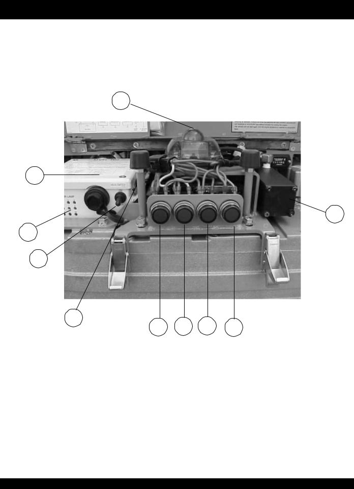
Figure 4. MVH-702DRSC Remote Control Components
PAGE 16 — MQ-MIKASA MVH-702DRSC COMPACTOR — PARTS & OPERATION MANUAL — REV. #1 (12/17/03)

MVH-702DRSC — REMOTE CONTROL COMPONENTS
CONTROL UNIT (BODY)
Figure 4 illustrates the location of the major components for the Remote Control on the body of the machine. The function of each component is described below:
1.Control Unit – Controls engine start/stop and hydraulic valve unit according to the operation signals from the transmitter. In addition, it also controls the following monitoring lights:
Receiving Failure Light
Oil Pressure (Engine) Failure Light
Regulator Failure Light
E/G Overheat Light
2. Receiver and Receiving Lamp – Receives infra-red signals from the transmitter indicated by the flashing light on the receiving lamp.
3. Main Switch (Battery Master Switch) –Battery power switch for control unit on body of machine.
4.Valve Unit – Electromagnetic and hydraulic valve; controls traveling speed and direction.
5.Cell/Crank Start Switch – Selects electric (cell) start for normal operation or manual (crank) start for emergencies.
6.Receiving Failure Light - Lights to indicate that the signal from the transmitter is not received. The remote control operation is restricted to a narrower area , the farther you are from the machine. When this light is on, plate vibration will automatically stop but the engine will continue running.
7.Oil Pressure (Engine) Failure Light –Lights to indicate that the engine oil is low or the hydraulic oil pump is not functioning properly. When this light is on, the engine will automatically stop.
8. Regulator Failure Light – Lights to indicate that the alternator and regulator are not functioning properly.When this light is on, the machine is still operating. Check alternator and regulator after operation.
9.E/G Overheat Light - Lights to indicate engine overheat. If the engine is continuously overloaded or if the air element is clogged due to excessive dust, the engine will overheat. To correct this, run the machine without vibration for about 5 minutes or stop the engine to clean air element. If this is not done, the machine will automatically stop vibration to cool the engine, and will not start again until the engine temperature reaches acceptable level.
10.Monitoring Lamp – Depending on which numbered lamps light up, indicates the status of the machine (Figure 5).
MONITOR LAMP
1 2 3 4
5 6 7 8
9 10 11 12
Figure 5. Monitor Lamp
1 is lighted: Main Switch is on.
9, 10, and 12 are lighted: Engine start by cell motor.
9 and 10 are lighted: Engine start by crank handle.
5 and 8 are lighted:Transmitter start switch is turned on. Shortly after the transmitter start switch is turned
on, all lamps turn off.
6 and 8 are lighted:Transmitter vibration start switch is on.
7, 8, and 12 are lighted:Transmitter start switch is turned off.
See Figure 6 for correlation of monitor lamp and joystick lever.
Figure 6. Correlation of Monitor Lamp
and Joystick Lever
MQ-MIKASA MVH-702DRSC COMPACTOR — PARTS & OPERATION MANUAL — REV. #1 (12/17/03) — PAGE 17
MVH-702DRSC — REMOTE CONTROL COMPONENTS
5 |
6 |
7 |
8 |
1
4
9
2 |
3 |
|
12
10 11
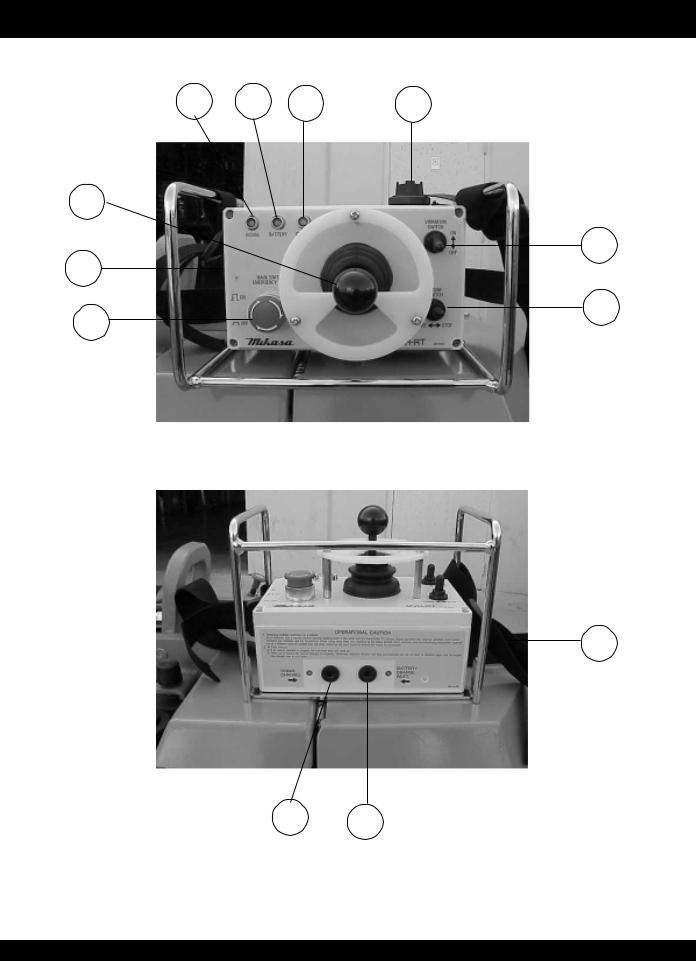
Figure 7. MVH-702DRSCTransmitter Components
PAGE 18 — MQ-MIKASA MVH-702DRSC COMPACTOR — PARTS & OPERATION MANUAL — REV. #1 (12/17/03)
 Loading...