


OPERATION & PARTS MANUAL
 SERIES
MODEL MVH-200GH
REVERSIBLE PLATE COMPACTOR
(HONDA GASOLINE ENGINE)
Revision #2 (09/22/06)
THIS MANUAL MUST ACCOMPANY
THE EQUIPMENT AT ALLTIMES.
PAGE 2 — MVH-200GH PLATE COMPACTOR — OPERATION & PARTS MANUAL — REV. #2 (09/22/06)

HERE'S HOW TO GET HELP
PLEASE HAVETHE MODEL AND SERIAL
NUMBER ON-HANDWHEN CALLING
MULTIQUIP CORPORATE OFFICE |
|
18910 Wilmington Ave. |
800-421-1244 |
Carson, CA 90746 |
FAX:310-537-3927 |
Email: mq@multiquip.com |
|
Internet:www.multiquip.com |
|
PARTS DEPARTMENT |
|
800-427-1244 |
FAX:800-672-7877 |
310-537-3700 |
FAX:310-637-3284 |
MAYCO PARTS |
|
800-306-2926 |
FAX:800-672-7877 |
310-537-3700 |
FAX:310-637-3284 |
SERVICE DEPARTMENT |
|
800-421-1244 |
FAX:310-537-4259 |
310-537-3700 |
|
TECHNICAL ASSISTANCE |
|
800-478-1244 |
FAX:310-631-5032 |
WARRANTYDEPARTMENT |
|
800-421-1244, EXT.279 |
FAX:310-537-1173 |
310-537-3700, EXT.279 |
|
© COPYRIGHT 2006, MULTIQUIP INC.
Multiquip Inc and the MQ logo are registered trademarks of Multiquip Inc. and may not be used, reproduced, or altered without written permission. All other trademarks are the property of thier respective owners and used with permission.
This manual MUST accompany the equipment at all times. This manual is considered a permanent part of the equipment and should remain with the unit if resold.
The information and specifications included in this publication were in effect at the time of approval for printing. Illustrations are based on the Mikasa MVH-200GH Plate Compactor. Illustrations, descriptions, references and technical data contained in this manual are for guidance only and may not be considered as binding. Multiquip Inc. reserves the right to discontinue or change specifications, design or the information published in this publication at any time without notice and without incurring any obligations.
To find the latest revision of this publication, visit our website at: www.multiquip.com
MVH-200GH PLATE COMPACTOR — OPERATION & PARTS MANUAL — REV. #2 (09/22/06) — PAGE 3

MIKASA SERIES MVH-200GH PLATE COMPACTOR
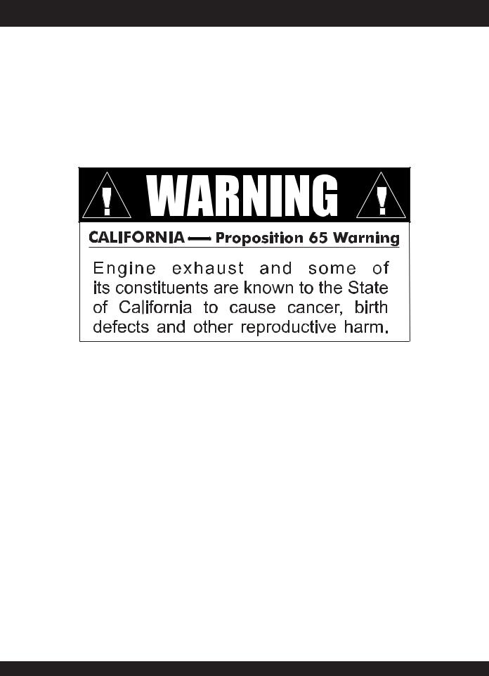
Proposition 65 Warning ............................................. |
2 |
Help & Copyright ....................................................... |
3 |
Table Of Contents ..................................................... |
4 |
Parts Ordering Procedures ....................................... |
5 |
Specifications ............................................................ |
6 |
Dimensions ............................................................... |
7 |
Safety Message Alert Symbols .............................. |
8-9 |
Rules for Safe Operation .................................... |
10-11 |
Operation and Safety Decals .................................. |
12 |
Features .................................................................. |
13 |
Plate Compactor Components................................ |
14 |
Engine Components ............................................... |
15 |
Pre-Inspection ......................................................... |
16 |
Operation ........................................................... |
17-20 |
Maintenance ...................................................... |
21-25 |
Troubleshooting ................................................. |
26-28 |
Explanation Of Code In Remarks Column .............. |
30 |
Suggested Spare Parts ........................................... |
31 |
COMPONENT DRAWINGS |
|
Decal Placement ................................................ |
32-33 |
Body Assembly .................................................. |
34-35 |
Vibration Assembly ............................................ |
36-39 |
Control (A-type) Assembly ................................. |
40-41 |
Pump (A-type) Assembly ................................... |
42-43 |
Throttle (A-type) Assembly ................................ |
44-47 |
TABLE OF CONTENTS
HONDA GX240K1SMX2 ENGINE
Air Cleaner Assembly......................................... |
46-47 |
Camshaft Assembly ........................................... |
48-49 |
Piston Assembly ................................................. |
50-51 |
Carburetor Assembly ......................................... |
52-53 |
Crankcase Cover Assembly............................... |
54-55 |
Crankshaft Assembly ......................................... |
56-57 |
Cylinder Barrel Assembly ................................... |
58-59 |
Cylinder Head Assembly .................................... |
60-61 |
Fan Cover Assembly .......................................... |
62-63 |
Flywheel Assembly ............................................ |
64-65 |
Fuel Tank Assembly ........................................... |
66-67 |
Ignition Coil Assembly ........................................ |
68-69 |
Gasket Kit Assembly .......................................... |
70-71 |
Muffler Assembly ............................................... |
72-73 |
Recoil Starter Assembly..................................... |
74-75 |
Control Assembly ............................................... |
76-77 |
Labels Assembly ................................................ |
78-79 |
Terms and Conditions of Sale ................................. |
80 |
Specification and part number are subject to change without notice.
PAGE 4 — MVH-200GH PLATE COMPACTOR — OPERATION & PARTS MANUAL — REV. #2 (09/22/06)
Effective: June 1st, 2005 |
PARTS ORDERING PROCEDURES |
www.multiquip.com


Ordering parts has never been easier!
Choose from three easy options:
Best Deal! Order via Internet (Dealers Only):
Order parts on-line using Multiquip’s SmartEquip website!
■View Parts Diagrams
■Order Parts
■Print Specification Information
Goto www.multiquip.com and click on
Order Parts to log in and save!
If you have an MQ Account, to obtain a Username and Password, E-mail us at: parts@multiquip.com.
To obtain an MQ Account, contact your District Sales Manager for more information.
Use the internet and qualify for a 5% Discount on Standard orders for all orders which include complete part numbers.*
Note: Discounts Are Subject To Change
|
|
|
Order via Fax (Dealers Only): |
|
|
|
|
|
|
|
|
|
|
|
|
|
|
|
|
|
|
|
|
|
|
|
|
|
|
|
|
|
|
|
|
Fax your order in and qualify for a 3% Discount |
|||||||||||||||||||||||||||
|
|
|
|
||||||||||||||||||||||||||||
|
|||||||||||||||||||||||||||||||
|
|
|
All customers are welcome to order parts via Fax. |
|
on Standard orders for all orders which include |
||||||||||||||||||||||||||
|
|||||||||||||||||||||||||||||||
|
|
|
|
||||||||||||||||||||||||||||
|
|
|
Domestic (US) Customers dial: |
|
complete part numbers.* |
||||||||||||||||||||||||||
|
|||||||||||||||||||||||||||||||
|
|
|
1-800-6-PARTS-7 (800-672-7877) |
|
|
|
|
|
|
|
|
|
|
|
|
|
|
|
|
|
|
|
|
|
|
|
|
|
|
|
|
|
|
|
|
|
|
|
|
|
|
|
|
|
|
|
|
|
|
|
|
|
|
|
|
|
|
|
|
||||
Note: Discounts Are Subject To Change
|
|
|
|
|
|
|
|
|
|
|
|
|
|
|
|
|
|
|
|
|
Order via Phone: Domestic (US) Dealers Call: |
|||||||||||||||||||||||||||||||||||||||||||
|
|
|
|
|
|
|
|
|
|
|
|
|
|
|
|
|
|
|
|
|
||||||||||||||||||||||||||||||||||||||||||||
|
|
|
|
|
|
|
|
|
|
|
|
|
|
|
|
|
|
|
|
|
|
|
|
|
|
|
|
|
|
|
|
|
1-800-427-1244 |
|
|
|
|
|
|
|
|
|
|
|
|
|
|
|
|
|
|
|
|
|
|
|||||||||
|
|
|
|
|
|
|
|
|
|
|
|
|
|
|
|
|
|
|
|
|
|
|
|
|
|
|
|
|
|
|
|
|
|
|
|
|
|
|
|
|
|
|
|
|
|
|
|
|
|
|
|
|
|
|
|
|
|
|
|
|
|
|
|
|
|
|
|
|
|
|
|
|
|
|
|
|
|
|
|
|
|
|
|
|
|
|
|
|
|
|
|
|
|
|
|
|
|
|
|
|
|
|
|
|
|
|
|
|
|
|
|
|
|
|
|
|
|
|
|
|
|
|
|
|
|
|
|
|
|
|
|
|
Non-Dealer Customers: |
|
|
|
|
|
|
|
|
|
|
|
|
International Customers should contact |
|
|||||||||||||||||||||||||||||||||||||||||||||||
|
|
|
|
|
|
|
|
|
|
|
|
|||||||||||||||||||||||||||||||||||||||||||||||||||||
|
|
|
|
|
|
|
|
|
|
|
|
|||||||||||||||||||||||||||||||||||||||||||||||||||||
|
|
|
Contact your local Multiquip Dealer for |
|
|
|
|
|
|
|
|
|
|
|
|
|
|
|||||||||||||||||||||||||||||||||||||||||||||||
|
|
|
|
|
|
|
|
|
|
|
|
|
|
|
|
|
||||||||||||||||||||||||||||||||||||||||||||||||
|
|
|
|
|
|
|
|
|
|
|
|
|
|
|
their local Multiquip Representatives for |
|
||||||||||||||||||||||||||||||||||||||||||||||||
|
|
|
parts or call 800-427-1244 for help in |
|
|
|
|
|
|
|
|
|
|
|
|
|
|
|||||||||||||||||||||||||||||||||||||||||||||||
|
|
|
|
|
|
|
|
|
|
|
|
|
|
|
Parts Ordering information. |
|
||||||||||||||||||||||||||||||||||||||||||||||||
|
|
|
locating a dealer near you. |
|
|
|
|
|
|
|
|
|
|
|
|
|
|
|||||||||||||||||||||||||||||||||||||||||||||||
|
|
|
|
|
|
|
|
|
|
|
|
|
|
|
|
|
|
|
|
|
|
|
|
|
|
|
|
|
|
|
|
|
|
|
|
|
|
|
||||||||||||||||||||||||||
|
|
|
|
|
|
|
|
|
|
|
|
|
|
|
|
|
|
|
|
|
|
|
|
|
|
|
|
|
|
|
|
|
|
|
|
|
|
|
|
|
|
|
|
|
|
|
|
|
|
|
|
|
|
|
|
|
|
|
|
|
|
|
|
|
|
|
|
|
|
|
|
|
|
|
|
|
When ordering parts, please supply: |
||||||||||||||||||||||||||||||||||||||||||||||||||||
|
Dealer Account Number |
Specify Preferred Method of Shipment: |
|
|
Dealer Name and Address |
Fed Ex/UPS |
DHL |
|
Shipping Address (if different than billing address) |
■ Priority One |
Truck |
■ Ground |
|
||
|
Return Fax Number |
|
|
■ Next Day |
|
||
|
Applicable Model Number |
|
|
■ Second/ThirdDay |
|
||
Quantity, Part Number and Description of Each Part
Unless otherwise indicated by customer, all orders are treated asStandard Orders and will ship NOTE within24hours.WewillmakeeveryefforttoshipAirShipmentsthesamedaytheorderisreceived,
if received prior to 2PM PST. Stock Orders must be noted on fax or web order form.
WE ACCEPT ALL MAJOR CREDIT CARDS!
MVH-200GH PLATE COMPACTOR — OPERATION & PARTS MANUAL — REV. #2 (09/22/06) — PAGE 5

MVH-200GH — SPECIFICATIONS
Table 1. MVH-200GH REVERSIBLE PLATE COMPACTOR SPECIFICATIONS
Centrifugal Force |
7,056 lbs. (3,200 kg) |
|
|
Vibration Frequency |
5,200 vpm |
|
|
Maximum Forward Speed |
75 ft/min (23 m/min) |
|
|
Plate Size (L x W) |
27.6 x 20 in (70 x 51 cm) |
|
|
Operating Weight |
423 lbs. (192 kg) |
|
|
Maximum Area Capacity |
7,515 sq. ft/hr (698 sq. m/hr) |
|
|
HP Rating |
8 BHP (5.9 kW) |
|
|
|
Table 2. ENGINE SPECIFICATIONS |
|
|
|
|
|
Model |
HONDA GX240K1SMX2 |
|
|
|
|
Type |
Air-cooled 4 stroke, Single Cylinder, OHV, |
|
Horizontal Shaft Gasoline Engine |
|
|
|
|
|
|
|
|
Bore X Stroke |
2.90 in. X 2.30 in. |
|
(73 mm x 58 mm.) |
|
|
|
|
|
|
|
|
Displacement |
14.81 cc |
Engine |
|
|
Max Output |
8.0 H.P./3600 R.P.M. |
|
|
|
|
|
Fuel Tank Capacity |
1.59 gallons (6 liters) |
|
|
|
|
Fuel |
Unleaded Automobile Gasoline |
|
|
|
|
Lube Oil Capacity |
2.33 pints |
|
|
|
|
Speed Control Method |
Centrifugal Fly-weight Type |
|
|
|
|
Starting Method |
Recoil Start |
|
|
|
Dimension |
|
14.0 x 16.9 X 16.1 in. |
(L x W x H) |
|
(355 X 430 X 410 mm.) |
|
|
|
Dry Net Weight |
|
55.1 lbs (25 Kg.) |
|
|
|
PAGE 6 — MVH-200GH PLATE COMPACTOR — OPERATION & PARTS MANUAL — REV. #2 (09/22/06)
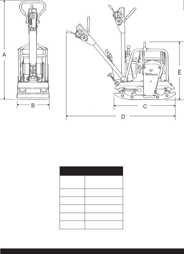
MVH-200GH — DIMENSIONS
Figure 1. MVH-200GH Reversible Plate Compactor Dimensions
TABLE 3. DIMENSIONS
REFERENCE |
DIMENSIONS |
LETTER |
IN. (MM) |
A49 in. (1245 mm.)
B21 in. (533 mm.)
C26.5 in. (673 mm.)
D48 in. (1219 mm.)
E31 in. (787 mm.)
MVH-200GH PLATE COMPACTOR — OPERATION & PARTS MANUAL — REV. #2 (09/22/06) — PAGE 7

MVH-200GH — SAFETY MESSAGE ALERT SYMBOLS
FORYOUR SAFETY ANDTHE SAFETY OF OTHERS!
Safety precautions should be followed at all times when operating this equipment. Failure to read and understand the Safety Messages and
Operating Instructions could result in injury to yourself and others.
This Owner's Manual has been developed to provide complete instructions for the safe and efficient operation of the Multiquip Model MVH200GH Reversible Plate Compactor.
Refer to the engine manufacturer’s instructions for data relative to its safe operation.
Before using this reversible plate compactor,ensure that the operating individual has read and understands all instructions in this manual.
SAFETY MESSAGE ALERT SYMBOLS
The three (3) Safety Messages shown below will inform you about potential hazards that could injure you or others. The
Safety Messages specifically address the level of exposure to the operator, and are preceded by one of three words:
DANGER, WARNING, or CAUTION.
DANGER
You WILL be KILLED or SERIOUSLY injured if you DO NOT follow directions.
WARNING
You CAN be KILLED or SERIOUSLY injured if you DO NOT follow directions.
CAUTION
You CAN be INJURED if you DO NOT follow directions.
Potential hazards associated with the operation of an MVH200GH Reversible Plate Compactor will be referenced with Hazard Symbols which appear throughout this manual, and will be referenced in conjunction with Safety Message Alert Symbols.
HAZARD SYMBOLS
WARNING - Lethan Exhaust Gasses
Engine exhaust gases contain poisonous carbon monoxide. This gas is colorless and odorless, and can cause death if inhaled. NEVER operate this equipment in a confined area or enclosed structure that does not provide ample free flow air.
WARNING - Explosive Fuel
Gasoline is extremely flammable, and its vapors can cause an explosion if ignited.
DO NOT start the engine near spilled fuel or combustible fluids.
DO NOT fill the fuel tank while the engine is running or hot. DO NOT overfill tank, since spilled fuel could ignite if it comes into contact with hot engine parts or sparks from the ignition system. Store fuel in approved containers, in well-ventilated areas and away from sparks and flames.
WARNING - Burn Hazards
Engine components can generate extreme heat. To prevent burns, DO NOT touch these areas while the engine is running or immediately after operations. Never operate the engine with heat shields or heat guards removed.
CAUTION - Respiratory Hazard
ALWAYS wear approved respiratory protection when required.
PAGE 8 — MVH-200GH PLATE COMPACTOR — OPERATION & PARTS MANUAL — REV. #2 (09/22/06)

MVH-200GH — SAFETY MESSAGE ALERT SYMBOLS
CAUTION - Rotating Parts
NEVER operate equipment with covers, or guards removed. Keep fingers, hands, hair and clothing away from all moving parts to prevent injury.
CAUTION - Accidental Starting
ALWAYS place the power source, circuit breakers or ON/OFF switch in the OFF position, when the generator is not in use, unless connected to transfer switch.
CAUTION - Sight and Hearing Hazards
ALWAYS wear approved eye and hearing protection.
CAUTION - Equipment Damage Messages
Other important messages are provided throughout this manual to help prevent damage to your light tower, other property, or the surrounding environment.
This reversible plate compactor, otherproperty,orthesurrounding environment could be damaged if you do not follow instructions.
MVH-200GH PLATE COMPACTOR — OPERATION & PARTS MANUAL — REV. #2 (09/22/06) — PAGE 9

MVH-200GH — RULES FOR SAFE OPERATION
WARNING - ReadThis Manual
Failure to follow instructions in this manual may lead to Serious Injury or even Death. This equipment is to be operated by trained and qualified personnel only! This equipment is for industrial use only.
The following safety guidelines should always be used when operating the Mikasa MVH-200GH Reversible Plate Compactor:
Safety:
■DO NOT operate or service this equipment before reading this entire manual.
■This equipment should not be operated by persons under 18 years of age.
■NEVER operate this equipment without proper protective clothing, shatterproof glasses, steel-toed boots and other protective devices required by the job.
■NEVER operate this equipment when not feeling well due to fatigue, illness or taking medicine.
■NEVER operate the saw under the influence or drugs or alcohol.
■NEVER use accessories or attachments, which are not recommended by Multiquip for this equipment. Damage to the equipment and/or injury to user may result.
■Manufacturer does not assume responsibility for any accident due to equipment modifications. Unauthorized equipment modification will void all warranties.
■Whenever necessary, replace nameplate, operation and safety decals when they become difficult read.
■ALWAYS check all the bolts on the light tower for tightness.
■NEVER touch the hot exhaust manifold, muffler or cylinder. Allow these parts to cool before servicing engine or generator.
■HighTemperatures – Allow the engine
to cool before adding fuel or performing service and maintenance functions. Contact with hot components can cause serious burns.
■The engine of this reversible plate compactor requires an adequate free flow of cooling air. NEVER operate the reversible plate compactor in any enclosed or narrow area where free flow of the air is
restricted. If the air flow is restricted it will cause serious damage to the reversible plate compactor or engine and may cause injury to people and property. Remember the vibration roller's engine gives off DEADLY gases.
■ALWAYS refuel in a well-ventilated area, away from sparks and open flames.
■ALWAYS use extreme caution when working with flammable liquids. When refueling, stop the engine and allow it to cool. DO NOT smoke around or near the machine. Fire or explosion could result from fuel vapors, or if fuel is spilled on a hot engine.
■NEVER operate the reversible plate compactor in an explosive atmosphere or near combustible materials. An explosion or fire could result causing severe bodily harm or even death.
■Topping-off to filler port is dangerous, as it tends to spill fuel.
■ALWAYS store the reversible plate compactor in a clean, dry location out of the reach of children.
■NEVER run engine without air cleaner. Severe engine damage may occur.
■NEVER leave the reversible plate compactor unattended, turn off engine.
■CAUTION must always be observed while servicing this reversible plate compactor.Rotating parts can cause injury if contacted.
■DO NOT leave reversible plate compactor with engine running.
■NEVER disconnect any "emergency or safety devices". These devices are intended for operator safety. Disconnection of these devices can cause severe injury, bodily harm or even death! Disconnection of any of these devices will void all warranties.
PAGE 10 — MVH-200GH PLATE COMPACTOR — OPERATION & PARTS MANUAL — REV. #2 (09/22/06)
MVH-200GH — RULES FOR SAFE OPERATION
Loading and Unloading (Crane):
■Before lifting, make sure that machine parts (hook and vibration insulator) are not damaged and screws are not loosened or lost.
■Always make sure crane or lifting device has been properly secured to the hook of guard frame on compactor.
■NEVER lift the machine while the engine is running.
■Use adequate lifting cable (wire or rope) of sufficient strength.
■Use one point suspension hook and lift straight upwards.
■NEVER allow any person or animal to stand underneath the machine while lifting.
■Try not to lift machine to unnecessary heights.
TRANSPORTING
■ALWAYS shutdown engine before transporting.
■Tighten fuel tank cap securely and close fuel cock to prevent fuel from spilling.
■Drain fuel when transporting compactor over long distances or bad roads.
■ALWAYS tie down the compactor during transportation by securing the compactor's guard frame with rope.
Maintenance Safety:
■NEVER lubricate components or attempt service on a running machine.
■ALWAYS allow the machine a proper amount of time to cool before servicing.
■Keep the machinery in proper running condition.
■Fix damage to the machine immediately and always replace broken parts.
■Dispose of hazardous waste properly. Examples of potentially hazardous waste are used motor oil, fuel and fuel filters.
■DO NOT use food or plastic containers to dispose of hazardous waste.
■DO NOT pour waste, oil or fuel directly onto the ground, down a drain or into any water source.
Emergencies:
■ALWAYS know the location of the nearest fire extinguisher.
■ALWAYS know the location of the nearest first aid kit.
■In emergencies always know the location of the nearest phone or keep a phone on
the job site. Also know the phone numbers of the nearest ambulance, doctor and fire department. This information will be invaluable in the case of an emergency.
MVH-200GH PLATE COMPACTOR — OPERATION & PARTS MANUAL — REV. #2 (09/22/06) — PAGE 11

MVH-200GH — OPERATION AND SAFETY DECALS
Figure 2 displays the operation and safety decals as they appear on the reversible plate compactor. Should any of these decals become damaged or unreadable, contact the Multiquip Parts Department for a replacement set.
Figure 2. Operation and Safety Decals
PAGE 12 — MVH-200GH PLATE COMPACTOR — OPERATION & PARTS MANUAL — REV. #2 (09/22/06)

Plate Compactor
The Mikasa MVH-200GH is a walk behind, reversible plate compactor designed for the compaction of sand, clay and asphalt. This plate compactor is a powerful compacting tool capable of applying a tremendous force in consecutive high frequency vibrations to a soil surface. Its applications include soil compacting for road, embankments and reservoirs as well as backfilling for gas pipelines, water pipelines and cable installation work.
Vibratory Plates
The vibratory plates of the MVH-200GH produce low amplitude high frequency vibrations, designed to compact granular soils.
The resulting vibrations cause forward motion.The engine and handle are vibration isolated from the vibrating plate.The heavier the plate, the more compaction force it generates.
ReversibleVibratory Plates
Reversible vibratory plates have two eccentric weights that allow a smooth transition for forward and reverse travel, plus increased compaction force as the result of dual weights.
Due to their weight and force, reversible plates are ideal for semi-cohesive soils.
MVH-200GH — FEATURES
Frequency/Speed
The compactor's vibrating plate maximum frequency is 5200 vpm (vibrations per minute).The forward and reverse travel speed of the compactor is approximately 75 ft./minute (23 meters/ minute).
Engine
The Mikasa MVH-200GH Plate Compactor is equipped with an air-cooled, 4-stroke, single-cylinder HONDA GX240K1SMX2 gasoline engine.
Controls
Before starting the MVH-200GH Plate Compactor, identify and understand the function of the controls and components as indicated in Figure 3.
MVH-200GH PLATE COMPACTOR — OPERATION & PARTS MANUAL — REV. #2 (09/22/06) — PAGE 13
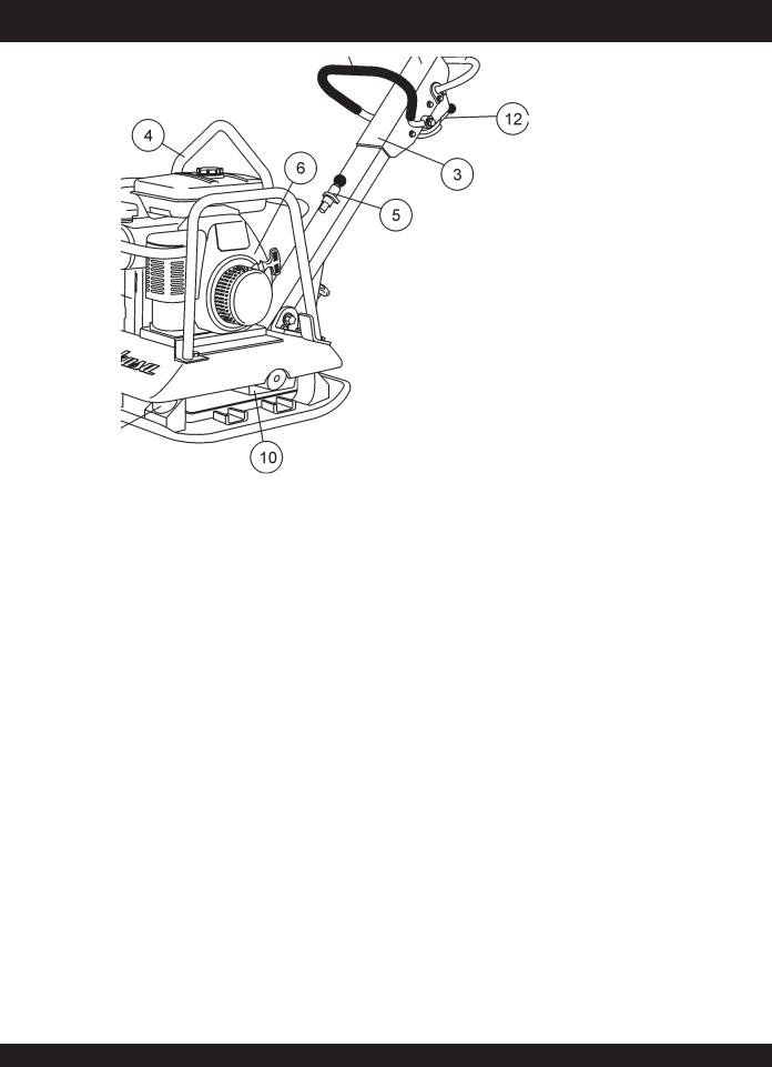
MVH-200GH — PLATE COMPACTOR COMPONENTS
Figure 3. MVH-200GH Components
Figure 3 illustrates the location of the major components for the MVH-200GH Reversible Plate Compactor.The function of each component is described below:
1. |
Hand Grip – When operating the compactor use this hand |
|
grip to maneuver the compactor. |
2. |
Forward & Reverse Lever – Push the lever forward, the |
|
compactor will move in a forward direction, pull the lever |
|
backwards, the compactor will move in backwards direction. |
|
Placing the lever in the middle (midway) will cause the |
|
compactor not to move (neutral). |
3. |
Handle Bar – When operating the compactor, this handle |
|
is to be in the downward position.When the compactor is |
|
to be stored, move the handle bar to the upright position. |
4.Guard Hook - Used to lift the machine with crane or other lifting device.
5.Stopper - Locks the handle in place in the upward position for stowing.
6. Engine – This plate compactor uses a HONDA GX240K1SMX2 engine. Refer to the owner’s manual for
|
engine information and related topics. |
7. |
Belt Cover – Remove this cover to gain access to the V- |
|
belts.NEVER run the compactor without theV-belt cover.If |
|
the V-belt cover is not installed, the possibility exist that |
|
your hand may get caught between the V-belt and clutch, |
|
thus causing serious injury and bodily harm. |
8. |
Base Plate – Designed to compact sand, clay, and asphalt. |
9. |
OilTank – Fill with proper grade of engine oil. |
10. Vibration Case – Encloses the eccentric, gears and counter weights.
11. Shock Absorber – Protects plate compactor from damage by absorbing vibration during operation.
12. Throttle Lever – Controls the speed of the plate compactor. Place straight vertically to start, push fully counterclockwise for full throttle and fully clockwise to stop plate compactor.
PAGE 14 — MVH-200GH PLATE COMPACTOR — OPERATION & PARTS MANUAL — REV. #2 (09/22/06)

MVH-200GH — ENGINE COMPONENTS
Figure 4. Engine Controls and Components
The engine shown above is a HONDA GX240K1SMX2 engine |
6. |
Choke Lever – Used in the starting of a cold engine, or in |
(Figure 4). The engine must be checked for proper lubrication |
|
cold weather conditions.The choke enriches the fuel mixture. |
and filled with fuel prior to operation. Refer to the manufacturers |
7. |
Air Cleaner – Prevents dirt and other debris from entering |
engine manual for instructions & details of operation and |
|
the fuel system. Remove wing-nut on top of air filter cannister |
servicing. |
|
to gain access to filter element. |
1. Fuel Filler Cap – Remove this cap to add unleaded gasoline |
|
Operating the engine without |
||
to the fuel tank.Make sure cap is tightened securely.DO NOT |
|
|||
|
an air filter, with a damaged |
|||
over fill. |
|
|||
|
air filter, or a filter in need of |
|||
|
|
|
||
|
|
|
replacement will allow dirt to |
|
CAUTION - FuelingThe Engine |
|
|
||
|
|
enter the engine, causing |
||
|
|
|
||
Adding fuel to the tank should be done only |
|
|
rapid engine wear. |
|
when the engine is stopped and has had an |
|
8. |
Spark Plug – Provides spark to the ignition system. Set spark |
|
opportunity to cool down. In the event of a fuel |
|
|
plug gap to 0.6 - 0.7 mm (0.028 - 0.031 inch) Clean spark |
|
spill, DO NOT attempt to start the engine until |
|
|
plug once a week. |
|
the fuel residue has been completely wiped |
|
9. |
Muffler – Used to reduce noise and emissions. |
|
up, and the area surrounding the engine is dry. |
|
|||
|
|
|
||
2. Throttle Lever – Used to adjust engine RPM speed (lever |
|
CAUTION - Burn Hazard |
||
|
|
|||
advanced forward SLOW, lever back toward operator FAST). |
Enginecomponentscangenerateextremeheat. |
|||
3. Engine ON/OFF Switch – ON position permits engine |
To prevent burns, DO NOT touch these areas |
|||
starting, OFF position stops engine operations. |
while the engine is running or immediately after |
|||
4. Recoil Starter (pull rope) – Manual-starting method. Pull |
operating. NEVER operate the engine with the |
|||
muffler removed. |
||||
the starter grip until resistance is felt, then pull briskly and |
||||
|
|
|||
smoothly. |
|
|
||
5. FuelValve Lever – OPEN to let fuel flow, CLOSE to stop the flow of fuel.
10. Fuel Tank – Holds unleaded gasoline. For additional information refer to engine owner's manual.
MVH-200GH PLATE COMPACTOR — OPERATION & PARTS MANUAL — REV. #2 (09/22/06) — PAGE 15

CAUTION - General Safety Precautions
NEVER operate the compactor in a confined area or enclosed area structure that does not provide ample free flow of air.
ALWAYS wear approved eye and hearing protection before operating the compactor.
Before Starting:
1.Read safety instructions at the beginning of manual.
2.Remove dirt and dust, particularly in the engine cooling air inlet, carburetor and air cleaner.
3.Check the air filter for dirt and dust.
If air filter is dirty, replace air filter with a new one as required.
4.Check carburetor for external dirt and dust.Clean with dry compressed air.
5.Check fastening nuts and bolts for tightness.
Engine Oil Check:
1.To check the engine oil level, place the compactor on secure level ground with the engine stopped.
2.Remove the filler dipstick from the engine oil filler hole (Figure 5) and wipe clean.
Figure 5. Engine Oil Dipstick (Removal)
MVH-200GH — PRE-INSPECTION
3.Insertandremovethedipstickwithoutscrewingitintothefiller neck. Check the oil level shown on the dipstick.
4.If the oil level is low (Figure 6), fill to the edge of the oil filler hole with the recommended oil type (Table 4).Maximum oil capacity is 1.16 quarts (1.1 liters).
Figure 6. Engine Oil Dipstick (Oil Level)
Table 4. Oil Type
Season |
Temperature |
Oil Type |
|
|
|
Summer |
25°C or Higher |
SAE 10W-30 |
|
|
|
Spring/Fall |
25°C~10°C |
SAE 10W-30/20 |
|
|
|
Winter |
0°C or Lower |
SAE 10W-10 |
|
|
|
WARNING - Explosive Fuel
Gasoline is extremely flammable, and its vapors can cause an explosion if ignited. DO NOT start the engine near spilled fuel or combustible fluids. DO NOT smoke while refueling.DO NOT attempt to refuel the pump if the engine is hot! or running.
Fuel Check:
1.Remove the gasoline cap located on top of fuel tank.
2.Visually inspect to see if the fuel level is low. If fuel is low, replenish with unleaded fuel.
3.Whenrefueling,besuretouseastrainerforfiltration.DONOT top-off fuel.Wipe up any spilled fuel immediately!
PAGE 16 — MVH-200GH PLATE COMPACTOR — OPERATION & PARTS MANUAL — REV. #2 (09/22/06)

MVH-200GH — START-UP PROCEDURES
This section is intended to assist the operator with the initial |
4. Placethechoke lever(Figure10)in the"CLOSED"position |
start-up of the compactor. It is extremely important that this |
if starting a warm engine or the temperature is warm. |
section be read carefully before attempting to use the compactor |
|
in the field. |
|
Starting the Engine (Honda engine):
1.Place the engine fuel valve lever (Figure 7) to the "ON" position.
Figure 10. Engine Choke Lever (Closed)
Figure 7. Engine FuelValve Lever (ON Position)
2.Move the throttle lever to the START position by opening it to about 20 degrees (Figure 8).
5.Place the engine ON/OFF switch (Figure 11) in the "ON " position.
Figure 11. Engine ON/OFF Switch (ON Position)
Figure 8. Throttle Lever (Start Position)
3.Place the choke lever (Figure 9) in the "OPEN " position if starting a cold engine.
6.Grasp the starter grip (Figure 12) and slowly pull it out.The resistancebecomesthehardestatacertainposition,corresponding to the compression point. Pull the starter grip briskly and smoothly for starting.
Figure 12. Starter Grip
Figure 9. Engine Choke Lever (Open)
MVH-200GH PLATE COMPACTOR — OPERATION & PARTS MANUAL — REV. #2 (09/22/06) — PAGE 17

MVH-200GH — START-UP/SHUT-DOWN PROCEDURES
7.If the engine has started, slowly return the choke lever (Figure 13 ) to the CLOSED position. If the engine has not started repeat steps 1 through 6.
Figure 13. Choke Lever (Closed)
8.Beforethecompactoris placedintooperation,runtheengine for several minutes. Check for fuel leaks, and noises that would be associated with a loose component.
Shut-Down Procedure:
1.Return the throttle lever to the START position. Allow the machine to cool down for 2 to 3 minutes.
2.Turn the throttle lever to the STOP position (Figure 16) to stop the engine. In a motor start, return the key switch to the STOP position (Figure 14) as soon as the engine stops.
Figure 14. Throttle Lever (Stop)
3.Turn the engine ON/OFF switch to the OFF position (Figure 15).
Figure 15. Engine ON/OFF Switch (OFF)
4. Placethefuelshut-off lever (Figure16) intheOFFposition.
Figure 16. Fuel Valve Lever (OFF)
Emergency Shutdown Proucedure:
1.Move the throttle lever quickly to the STOP position (Figure 14).
2.Place the engine ON/OFF switch in the OFF position (Figure 15).
PAGE 18 — MVH-200GH PLATE COMPACTOR — OPERATION & PARTS MANUAL — REV. #2 (09/22/06)

Traveling:
1.Grasp the compactor's hand grip and move the throttle lever (Figure17)quicklytothefastposition.Thecompactorwillnot operate correctly until the engine speed is high enough to engage the centrifigal clutch (approximately 2300 RPMs)
Figure 17. Throttle Lever (Fast)
Always move the throttle lever quickly without hesitation, because increasing the engine speed slowly causes the clutch to slip.
2.To make the compactor travel forwards, push the travel lever forward(Figure18).Tomakethecompactortravelbackward, pull the travel lever back (Figure 18).
Figure 18. Travel Lever
5.Slowly walk behind the compactor and be on the lookout for anylargeobjectsorforeignmatterthatmightcausedamage to the compactor or bodily injury.
6.Iftravelleverisplacedintheneutralposition,themachinewill vibrate in place.
MVH-200GH — OPERATION
To Turn The Compactor:
1.Move the travel lever to the NEUTRAL position.
2.Holdthehandgripfirmlyandturnthecompactorinthedesired direction.DONOTswingcompactorwhilegrippingthetravel lever.
Wheneverthecompactor'svibration becomes weak or lost during normal operation regardless of operation hours, check theV-belt and clutch immediately.
MVH-200GH PLATE COMPACTOR — OPERATION & PARTS MANUAL — REV. #2 (09/22/06) — PAGE 19
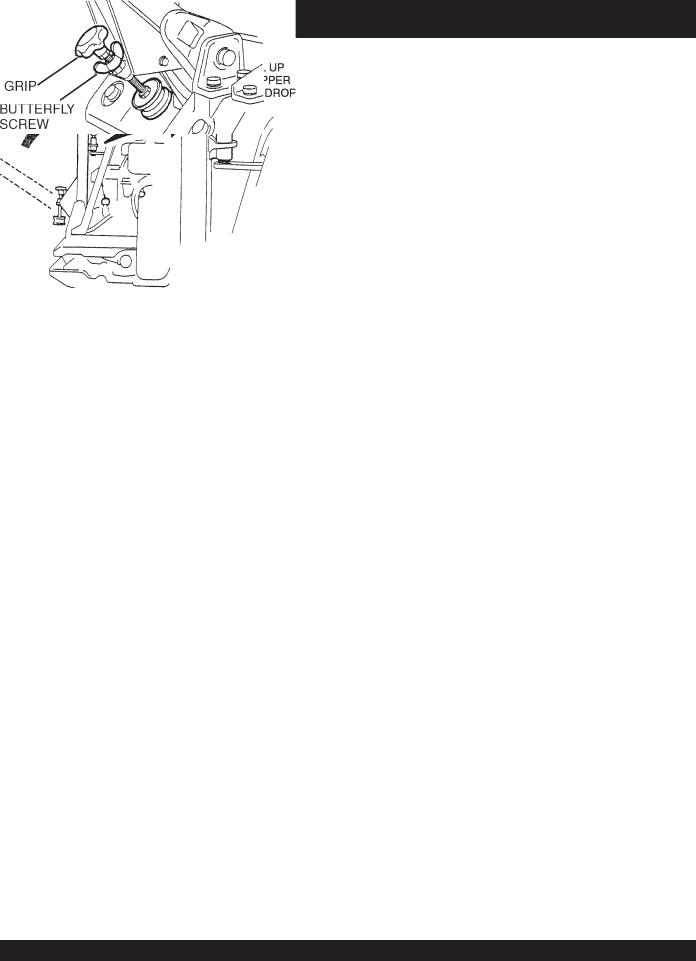
Adjusting Handle Height:
The height of the handle is adjustable for your comfort .
1.Loosen the butterfly screw (Figure 19).
2.Turnthegripclockwisetoraisethehandleorcounterclockwise to lower the handle.
3.When the handle is raised to the desired height, tighten the butterflyscrew.
Figure 19. Handle Adjustment
Stowing the Handle:
1.Push up the handle (Figure 20).
2.Pull the stopper grip upward into the hole of the guard frame to lock the handle.
Figure 20 . Stowing the Handle
MVH-200GH — OPERATION
Lifting:
1.Use a crane or lift to load and unload the machine. A skilled crane operator is required to perform the job.
2.When lifting the machine, check for any damaged or loose bolts, lifting hooks, and shock mounts.
3.Check any damaged or loose bolts in the guard frame to avoid machine sliding off.
4.Make sure that the machine is shut off before machine is lifted.
5.Use reliable cable for lifting.
6.Always lift the machine vertically and keep the machine away from workers and animals.
7.Do not lift the machine higher than the required height.
Transporting:
1.Always make sure that the machine is shut off while being transported.
2.Check that the fuel cap is properly closed and tightened.
3.When traveling long distances or on rugged terrain, drain the fuel of the machine before transporting.
4.Tie down the machine securely on the transportation so that it will not move or topple over.
PAGE 20 — MVH-200GH PLATE COMPACTOR — OPERATION & PARTS MANUAL — REV. #2 (09/22/06)
MVH-200GH — MAINTENANCE
CAUTION - General Maintenance Safety
Inspection and other services should always be carried out on hard and level ground with the engine shutdown.
Inspection and Maintenance ServiceTables.
To make sure your plate compactor is always in good working condition before using, carry out the maintenance inspection in accordance with Tables 5 through 7.
TABLE 5. MVH-200GH MACHINE INSPECTION
ITEM |
HOURS OF |
REMARKS |
|
OPERATION |
|||
|
|
||
|
|
|
|
Loose or Missing |
Every 8 hours |
|
|
Screws |
(every day) |
|
|
|
|
|
|
Damaged Parts |
Every 8 hours |
|
|
(every day) |
|
||
|
|
||
|
|
|
|
Function of Controlling |
Every 8 hours |
|
|
System Part |
(every day) |
|
|
|
|
|
|
Hydraulic System Leak |
Every 100 hours |
|
|
|
|
|
|
Vibrator Oil Check |
Every 100 hours |
See page 23 |
|
|
|
|
|
Vibrator Oil |
Every 300 hours |
See page 23 |
|
Replacement |
|||
|
|
||
|
|
|
|
Hydraulic Oil Check |
Every 100 hours |
See page 23 |
|
|
|
|
|
Hydraulic Oil |
First after 200 |
|
|
hours, then every |
See page 24 |
||
Replacement |
|||
1,000 hours |
|
||
|
|
||
|
|
|
|
V-belt (clutch) Check |
Every 200 hours |
See page 23 |
|
|
|
|
|
Battery Check |
Every 100 hours |
See page 25 |
|
|
|
|
These inspection intervals are for operation under normal conditions. Adjust your inspection intervals based on the number hours plate compactor is in use, and particular working conditions. Fuel piping and connections should be replaced every 2 years.
TABLE 6. MVH-200GH ENGINE CHECK
ITEM |
HOURS OF OPERATION |
|
|
|
|
Spark Plug Check |
Every 40 hours (every week) |
|
|
|
|
Oil or Fuel Leak |
Every 8 hours (every day) |
|
|
|
|
Tightness of Fastening |
Every 8 hours (every day) |
|
Threads |
||
|
||
|
|
|
Engine Oil Check and |
Every 8 hours (every day) |
|
(Replenish to specified maximum |
||
Replenishment |
||
level) |
||
|
||
|
|
|
Engine Oil Replacement |
After first 25 hours then every 50 to |
|
100 hours |
||
|
||
|
|
|
Air Filter Cleaning |
Every 100 hours |
|
|
|
See separate engine manual for details on engine check.
Daily Service
zCheck for leakage of fuel or oil.
zCheck for loose screws including tightness. See Table 6 below (tightening torque ), for retightening:
TABLE 7.
TIGHTENING TORQUE (in. kg/cm) Diameter
Material |
6mm |
8mm |
10mm |
12mm |
14mm |
16mm |
18mm |
20mm |
|
|
|
|
|
|
|
|
|
4T |
70 |
150 |
300 |
500 |
750 |
1,100 |
1,400 |
2,000 |
|
|
|
|
|
|
|
|
|
6-8T |
100 |
250 |
500 |
800 |
1,300 |
2,000 |
2,700 |
3,800 |
|
|
|
|
|
|
|
|
|
11T |
150 |
400 |
800 |
1,200 |
2,000 |
2,900 |
4,200 |
5,600 |
|
|
|
|
|
|
|
|
|
* |
100 |
300~ |
650 ~ |
|
|
|
|
|
350 |
700 |
|
|
|
|
|
||
|
|
|
|
|
|
|
||
|
|
|
|
|
|
|
|
|
* (In case counter-part is of aluminum)
(Threads in use with this machine are all right handed)
Material and quality of material is marked on each bolt, and screw.
zRemove soil and clean the bottom of compaction plate.
zCheck hydraulic pump, piping and hose for any leakage. A loosened hydraulic hose can be a cause for leakage. Check hydraulic hose connections with wrench applied for tightness.
zCheck engine oil.
MVH-200GH PLATE COMPACTOR — OPERATION & PARTS MANUAL — REV. #2 (09/22/06) — PAGE 21
Spark Plug:
1.Remove and clean the spark plug (Figure 21).
2.Adjust the spark gap to 0.028 ~0.031 inch (0.6~0.7 mm).This unit has electronic ignition, which requires no adjustments.
Figure 21. Spark Plug Gap
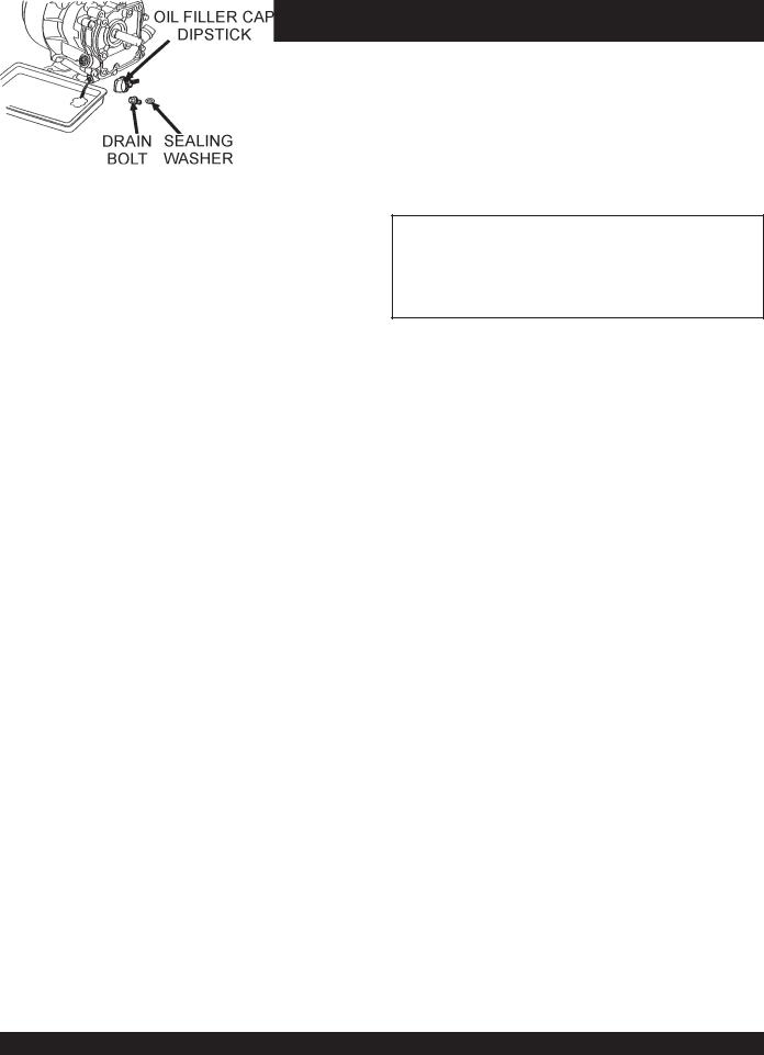
Engine Oil Replacement:
1.Replace engine oil, first in 25 hours of operation and every 50 to 100 hours afterwards.
2.Drain the engine oil when the oil is warm as shown in Figure 22.
3.Remove the oil drain bolt and sealing washer and allow the oil to drain into a suitable container.
4.Replace engine oil with recommended type oil as listed in Table 3. Engine oil capacity is 1.16 quarts (1.1 liters). DO NOT overfill.
5.Install drain bolt with sealing washer and tighten securely.
Figure 22. Engine Oil (Draining)
MVH-200GH — MAINTENANCE
Air Filter:
1.Remove the air cleaner cover and foam filter element as shown in Figure 23.
2.Tapthepaperfilterelement(Figure23)severaltimesonahard surfacetoremovedirt,orblowcompressedair[notexceeding 30psi(207kPa,2.1kgf/cm2)]throughthefilterelementfromthe air cleaner case side.
CAUTION - Cleaning the Engine Air Filter
NEVER brushoffdirt.Brushingwillforcedirtintothefibersand causepoorperformanceinyourairfilter.Replacethepaperfilter element if it is excessively dirty.
3.Clean foam element in warm, soapy water or nonflammable solvent. Rinse and dry thoroughly. Dip the element in clean engineoilandcompletelysqueezeouttheexcessoilfromthe element before installing.
Figure 23. Engine Air Filter
Hydraulic Oil
1.Check hydraulic oil in every 100 hours of operation. With handle bar positioned vertically (storage position), remove oil level check plug (Figure 23) from the top of hydraulic pump and check for proper oil level.
2.Replace hydraulic oil after first 200 hours and in every 1,000 hours of operation.
Figure 23. Oil Level Check Plug
PAGE 22 — MVH-200GH PLATE COMPACTOR — OPERATION & PARTS MANUAL — REV. #2 (09/22/06)

Checking and Replacing the V-Belt and Clutch:
After 200 hours of operation, remove the belt cover to check the V-belt tension (Figure 24).
Figure 24. V-Belt Check
CAUTION - Checking and Replacing theV-Belt
NEVERattempttochecktheV-beltwith the engine running. Severe injury can occurifyourhandgetscaughtbetween the V-belt and the clutch. Always use safetygloves.
Checking theV-belt
1.Tension is proper if the belt bends about 10 mm when depressed strongly with finger between shafts. Loose or worn V-belts reduces power transmission efficiency, causing weak compaction and reduces the life of the belt itself.
Replacing theV-belt
1.Remove the belt cover.
2.Engage an offset wrench (19 mm) or the like to vibrator pulley (lower) fastening bolt.
3.Engage waste cloth or the like at midway of V-belt on the left side and while pulling it back strongly, rotate the offset wrench clockwise so that the V-belt will come off.
4.Check the clutch and replace as necessary, following the procedures listed in Checking the Clutch.
5.Engage V-belt to lower vibrator pulley and push the V-belt to the left side of the upper clutch and the rotate offset wrench clockwise so that the V-belt moves onto the pulley.
MVH-200GH — MAINTENANCE
Checking the Clutch
1.With belt cover removed, visually check outer drum of the clutch for seizure and "V" groove for wear or damage.
2.Clean the "V" groove as necessary.
3.Check the clutch lining and shoe for signs of wear. If the shoe is worn, replace the clutch to prevent deficient power transmission and slippage.
Replacing the Clutch
1.RemoveV-belt.
2.Remove bolt at engine power output by giving a shock to an engaged wrench (e.g. tapping with hammer) and rotate the bolt counterclockwise.
3.Remove clutch with a pulley extractor.
4.To install a new clutch, reverse steps 1-3.
Vibrator Oil Level Check
CAUTION - Checking and Replacing theV-Belt
Always clean the area around the vibrator oil level check hole beforeremovingoilcheckplug.Thiswillpreventdirtanddebris fromenteringthesystem.
1.In every 100 hours of operation, with the machine positioned horizontally, remove vibrator oil level check plug (Figure 26) off vibrator (19 mm wrench) and see if oil is up to filler port.Be sure to clean area around check hole to prevent dirt and dust from entering.
2.In every 300 hours of operation, replace oil (capacity 1,500 cc). For draining oil through level check hole, have the machine inclined with a sleeper or the like placed under the compaction plate on opposite side.
*Use engine oil 10W-30 for this lubrication.
Figure 26. Vibrator Oil Maintenance
MVH-200GH PLATE COMPACTOR — OPERATION & PARTS MANUAL — REV. #2 (09/22/06) — PAGE 23

CAUTION - Filling the Hydraulic Oil Reservoir
Make sure hydraulic oil i is at a normal safe operating level. DO NOT over fill. Over filling (excessive oil) will cause excess oil to blow out of breather plug.
Replacing Hydraulic Oil
1.Remove the hydraulic hoses (left and right) which enters the cylinder of the vibrator from the hydraulic pump (Figure 28) and move the travel lever back and forth to drain the hydraulic oil from the pump.
Figure 28. Hydraulic Oil Maintenance
2.After draining, reinstall the hydraulic hoses and lock the travel lever to the sub-handle at reverse side (at MAXIMUM position) using a rope and with the reservoir cover at the top of the and pump removed.
3.Remove the bleed valve assembly within the pump using a 17 mm box wrench.
CAUTION - Removing the BleedValve
Whenremovingthebleedvalve,NEVERloosentheM8nuton its end. A copper packing is used underneath the bleed valve, thereforecareshouldbetakennottodropitintothepump.Make sure to remove it together with the bleed valve.DO NOT allow dust or trash to enter the hand pump.
3.Remove bleed plug at the cylinder of the vibrator (right belt cover side, forward travel circuit) (Figure 29). After a while, oil will flow out of the bleed plug. When aeration disappears, reinstall the plug, tightening it securely.
MVH-200GH — MAINTENANCE
4.Filling the forward travel circuit with oil.
a.With the rope removed from the travel lever, move the lever slowly up and down while adding oil into the hand pump. Use Shell Tellus Oil #46 or equivalent.
Figure 29. Hydraulic System
b.Moving it about 10 times causes the forward resistance to increase. When the resistance has considerably increased, with the travel lever remaining on the reverse side, install the bleed valve assembly loosely inside the pump to prevent oil splash.
c.Push the travel lever forward all the way.The valve inside the spool will activate to push out the aerated oil reverse circuit.
d.With the bleed valve assembly removed, repeat step c, two to three times.
PAGE 24 — MVH-200GH PLATE COMPACTOR — OPERATION & PARTS MANUAL — REV. #2 (09/22/06)

5.Filling the reverse travel circuit with oil.
a.With the travel lever pushed forward (hydraulic circuit is connected with reverse travel circuit), add oil into pump and remove bleed plug of vibrator cylinder (opposite of belt cover side). In a few seconds, oil will come out of bleed plug.
b.When aeration disappears, reinstall the plug tightly.
c.Move the travel lever slowly until aeration in the hand pump disappears (about 10 to 15 times).
6.When the aeration in the pump disappears, with the travel lever pushed forward, reinstall the valve. Be careful not to drop the packing into pump. The bleeding valve tightening torque is 450 to 500 kg-gm.
7.After installing the bleed valve, moving the travel lever all the way to reverse causes excess oil to be discharged into pump. If valve fails to activate, aeration still remains in the circuit. With the bleed valve removed, operate travel lever again to bleed. If valve is activated, move the travel lever forward to activate the valve inside spool before moving it to reverse to activate the bleed valve. Repeat 3 to 4 times.
8.After making sure that the hydraulic oil in the pump is at the specified level, reinstall the reservoir cover. Coat both sides of packing with liquid packing (such as Threebond #1215).
CAUTION - Overfilling the Hydraulic Oil Resevoir
Make sure that hand pump is filled with hydraulic oil to the specified level. Excessive oil may hinder bleed valve function, resulting in poor reverse performance.
9.After adding oil and reinstalling the reservoir cover, operate the travel lever to make sure of the following:
a.spool valve: when pushed forward, resistance is felt in two-stage motion.
MVH-200GH — MAINTENANCE
Battery Maitenance
CAUTION - Battery Maintenance Safety
Wear safety glasses or face mask, protective clothes, and rubber gloves when working with battery.
1.Check the battery terminals periodically to ensure that they are in good condition.
2.Use wire brush or sand paper to clean the battery terminals.
3.Check battery for cracks or any other damage. If white pattern appears inside the battery or paste has accumulated at the bottom, replace the battery.
4.If the machine will not be in operation for a long period of time, store in cool dry place and check the battery charge level every month to maintain the performance of the battery.
Battery Cable Connection
1.Take off the battery cover by removing the M6 nuts (Figure 30).
2.When removing cable, disconnect the ground side (normally negative) first (Figure 30).
3.When installing cable connect the ground side (normally negative) last.
Figure 30. Battery Maintenance
MVH-200GH PLATE COMPACTOR — OPERATION & PARTS MANUAL — REV. #2 (09/22/06) — PAGE 25
 Loading...