


OPERATION AND PARTS MANUAL
 SERIES
MODEL MT75HS
TAMPING RAMMER
(ROBIN EC12HS GASOLINE ENGINE)
Revision #11 (01/12/12)
To find the latest revision of this publication, visit our website at: www.multiquip.com
PROPOSITION 65 WARNING
PAGE 2 — MT75HS RAMMER — OPERATION AND PARTS MANUAL — REV. #11 (01/12/12)

NOTES
MT75HS RAMMER — OPERATION AND PARTS MANUAL — REV. #11 (01/12/12) — PAGE 3

TABLE OF CONTENTS
MT75HS Tamping |
|
ROBIN EC-12HS ENGINE |
|
Rammer |
|
Crankcase and Cylinder Assembly ................ |
32-33 |
Proposition 65 Warning ......................................... |
2 |
Crankshaft and Piston Assembly ................... |
34-35 |
Table Of Contents ................................................. |
4 |
Governor Assembly ....................................... |
36-37 |
Parts Ordering Procedures ................................... |
5 |
Muffler and Air CleanerAssembly .................. |
38-39 |
Safety Information .............................................. |
6-9 |
Carburetor and Oil Pump Assembly .............. |
40-41 |
General Information ............................................ |
10 |
Recoil Starter and Blower Assembly ............. |
42-43 |
Specifications ...................................................... |
11 |
Magneto Assembly ..................................... |
44-45 |
Controls and Components .................................. |
12 |
Loose Parts Assembly ................................... |
46-47 |
Operation ....................................................... |
13-15 |
|
|
Maintenance .................................................. |
16-17 |
Terms and Condition of Sale — Parts |
48 |
Troubleshooting Guide ................................... |
18-19 |
||
Explanation Of Codes In Remarks Column ........ |
20 |
|
|
Suggested Spare Parts ....................................... |
21 |
|
|
Component Drawings |
|
|
|
Name Plate and Decals ................................. |
22-23 |
|
|
Crankcase and Engine Assembly .................. |
24-25 |
|
|
Cylinder Guide and Foot Assembly ............... |
26-27 |
|
|
Tank and Handle Assembly ........................... |
28-31 |
|
|
NOTICE
Specification and part number are subject to change without notice.
PAGE 4 — MT75HS RAMMER — OPERATION AND PARTS MANUAL — REV. #11 (01/12/12)
www.multiquip.com

PARTS ORDERING PROCEDURES
|
|
|
|
|
|
Ordering parts has never been easier! |
|||||||||
|
|
|
|
|
|
|
Choose from three easy options: |
||||||||
|
|
|
|
|
|
|
|
|
|
|
|
Effective: |
|||
|
|
|
|
|
|
|
|
|
|
|
|
January 1st, 2006 |
|||
Best Deal! Order via Internet (Dealers Only): |
|
|
If you have an MQ Account, to obtain a Username |
||||||||||||
|
|
|
Order parts on-line using Multiquip’s SmartEquip website! |
|
|
||||||||||
|
|
|
|
|
and Password, E-mail us at: parts@multiquip. |
||||||||||
|
|
|
|
■ View Parts Diagrams |
|
|
com. |
||||||||
|
|
|
|
■ Order Parts |
|
|
To obtain an MQ Account, contact your |
||||||||
|
|
|
|
■ Print Specification Information |
|
|
District Sales Manager for more information. |
||||||||
|
|
|
|
|
|
|
|
|
|
|
|
||||
|
|
|
|
|
Goto www.multiquip.com and click on |
|
|
Use the internet and qualify for a 5% Discount |
|
|
|||||
|
|
|
|
|
|
|
|
||||||||
|
|
|
|
|
|
|
|
|
|
|
|
on Standard orders for all orders which include |
|||
|
|
|
|
|
|
Order |
Parts |
to log in and save! |
|||||||
|
|
|
|
|
|
|
|
|
|
|
|
complete part numbers.* |
|||
|
|
|
|
|
|
|
|
|
|
||||||
|
|
|
|
|
|
|
|
|
|
|
|
|
|
|
|
|
|
|
|
|
|
|
|
|
|
|
|
Note: Discounts Are Subject To Change |
|||
|
|
|
|
|
|
|
|
|
|||||||
|
|
|
|
|
|
Order via Fax (Dealers Only): |
|
|
|
|
|
|
|
||
|
|
|
|
|
|
|
|
Fax your order in and qualify for a 2% Discount |
|
|
|||||
|
|
|
|
|
|
All customers are welcome to order parts via Fax. |
|
on Standard orders for all orders which include |
|||||||
|
|
|
|
|
|
|
|||||||||
|
|
|
|
|
|
Domestic (US) Customers dial: |
|
complete part numbers.* |
|||||||
|
|
|
|
|
|
1-800-6-PARTS-7 (800-672-7877) |
|
|
|
|
|
|
|
||
|
|
|
|
|
|
|
|
|
Note: Discounts Are Subject To Change |
||||||
|
|
|
|
|
|
|
|
|
|||||||
|
|
|
|
|
|
|
|
|
|
|
|
||||
|
|
|
|
|
|
|
|
|
|
|
|
|
|
|
|
|
|
|
|
|
|
|
Order via Phone: Domestic (US) Dealers Call: |
|||||||||||
|
|
|
|
|
|
|||||||||||||
|
|
|
|
|
|
|
|
|
|
|
|
|
1-800-427-1244 |
|
|
|||
|
|
|
|
|
|
|
|
|
|
|
|
|
|
|
|
|
|
|
|
|
|
|
|
|
|
|
|
|
|
|
|
|
|
|
|
|
|
|
|
|
Non-Dealer Customers: |
|
|
|
|
|
|
|
|
|
|
|||||
|
|
|
|
|
|
International Customers should contact |
||||||||||||
|
|
|
Contact your local Multiquip Dealer for |
|
|
|
||||||||||||
|
|
|
|
|
|
their local Multiquip Representatives for |
||||||||||||
|
|
|
parts or call 800-427-1244 for help in |
|
|
|
||||||||||||
|
|
|
|
|
|
|||||||||||||
|
|
|
|
|
|
Parts Ordering information. |
||||||||||||
|
|
|
locating a dealer near you. |
|
|
|
||||||||||||
|
|
|
|
|
|
|
|
|
||||||||||
|
|
|
|
|
|
|
|
|
|
|
|
|
|
|
|
|||
|
|
|
When ordering parts, please supply: |
|||||||||||||||
|
Dealer Account Number |
Specify Preferred Method of Shipment: |
|
|
Dealer Name and Address |
UPS/Fed Ex |
DHL |
|
Shipping Address (if different than billing address) |
Priority One |
Truck |
|
Return Fax Number |
Ground |
|
Next Day |
|
||
|
Applicable Model Number |
|
|
Second/Third Day |
|
||
|
|
|
|
Quantity, Part Number and Description of Each Part
 NOTICE
All orders are treated as Standard Orders and will ship the same day if received prior to 3PM PST.
WE ACCEPT ALL MAJOR CREDIT CARDS!
MT75HS RAMMER — OPERATION AND PARTS MANUAL — REV. #11 (01/12/12) — PAGE 5

SAFETY INFORMATION
Do not operate or service the equipment before reading the entire manual. Safety precautions should be followed at all times when operating this equipment.
Failure to read and understand the safety messages and operating instructions could
result in injury to yourself and others.
SAFETY MESSAGES
The four safety messages shown below will inform you about potential hazards that could injure you or others.The safety messages specifically address the level of exposure to the operator and are preceded by one of four words:
DANGER,WARNING, CAUTION or NOTICE.
SAFETY SYMBOLS
 DANGER
Indicates a hazardous situation which, if not avoided,
WILL result in DEATH or SERIOUS INJURY.
 WARNING
Indicates a hazardous situation which, if not avoided,
COULD result in DEATH or SERIOUS INJURY.
 CAUTION
Indicates a hazardous situation which, if not avoided,
COULD result in MINOR or MODERATE INJURY.
NOTICE
Addresses practices not related to personal injury.
Potential hazards associated with the operation of this equipment will be referenced with hazard symbols which may appear throughout this manual in conjunction with safety messages.
PAGE 6 — MT75HS RAMMER — OPERATION AND PARTS MANUAL — REV. #11 (01/12/12)
SAFETY INFORMATION
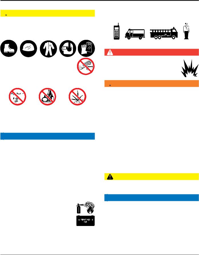
GENERAL SAFETY
 CAUTION
NEVER operate this equipment without proper protective clothing, shatterproof glasses, respiratory protection, hearing protection, steel-toed boots and other protective devices required by the job or city and state regulations.
NEVER operate this equipment when not feeling well due to fatigue, illness or when under medication.
NEVER operate this equipment under the influence of drugs or alcohol.
ALWAYS check the equipment for loosened threads or bolts before starting.
DO NOT use the equipment for any purpose other than its intended purposes or applications.
NOTICE
This equipment should only be operated by trained and qualified personnel 18 years of age and older.
Whenever necessary, replace nameplate, operation and safety decals when they become difficult read.
Manufacturer does not assume responsibility for any accident due to equipment modifications. Unauthorized equipment modification will void all warranties.
NEVER use accessories or attachments that are not recommended by Multiquip for this equipment. Damage to the equipment and/or injury to user may result.
ALWAYS know the location of the nearest
fire extinguisher.
ALWAYS know the location of the nearest
first aid kit.
ALWAYS know the location of the nearest phone or keep a phone on the job site. Also, know the phone numbers of the nearest ambulance, doctor and fire department. This information will be invaluable in the case of an emergency.
RAMMER SAFETY
DANGER
NEVER operate the equipment in an explosive atmosphere or near combustible materials.An explosion or fire could result causing severe bodily harm or even death.
 WARNING
NEVER disconnect any emergency or safety devices.
These devices are intended for operator safety. Disconnection of these devices can cause severe injury, bodily harm or even death. Disconnection of any of these devices will void all warranties.
DO NOT use this machine on ground that is harder than the machine can handle, or for driving pilings or tamping rock beds. Furthermore, use of the machine on sloping ground, such as the side of an embankment, may make the machine unstable and can cause an accident. It can also result in premature machine wear due to uneven loads on the machine.
Use the machine with confidence for tamping earth and sand, soil, gravel, and asphalt. DO NOT use the machine for other types of jobs.
CAUTION
NEVER lubricate components or attempt service on a running machine.
NOTICE
ALWAYS keep the machine in proper running condition.
Fix damage to machine and replace any broken parts immediately.
ALWAYS store equipment properly when it is not being used. Equipment should be stored in a clean, dry location out of the reach of children and unauthorized personnel.
MT75HS RAMMER — OPERATION AND PARTS MANUAL — REV. #11 (01/12/12) — PAGE 7
SAFETY INFORMATION
ENGINE SAFETY
 DANGER
The engine fuel exhaust gases contain poisonous carbon monoxide. This gas is colorless and odorless, and can cause death if inhaled.
The engine of this equipment requires an adequate free flow of cooling air.NEVER operate this equipment in any enclosed
or narrow area where free flow of the air is restricted. If the air flow is restricted it will cause injury to people and property and serious damage to the equipment or engine.
 WARNING
DO NOT place hands or fingers inside engine compartment when engine is running.
NEVER operate the engine with heat shields or guards removed.
DO NOT remove the engine oil drain plug while the engine is hot. Hot oil will gush out of the oil tank and severely scald any persons in the general area of the rammer.
 CAUTION
NEVER touch the hot exhaust manifold, muffler or cylinder. Allow these parts to cool
before servicing equipment.
NOTICE
NEVER run engine without an air filter or with a dirty air filter. Severe engine damage may occur. Service air filter frequently to prevent engine malfunction.
NEVER tamper with the factory settings of the engine or engine governor. Damage to the engine or equipment can result
if operating in speed ranges above the  maximum allowable.
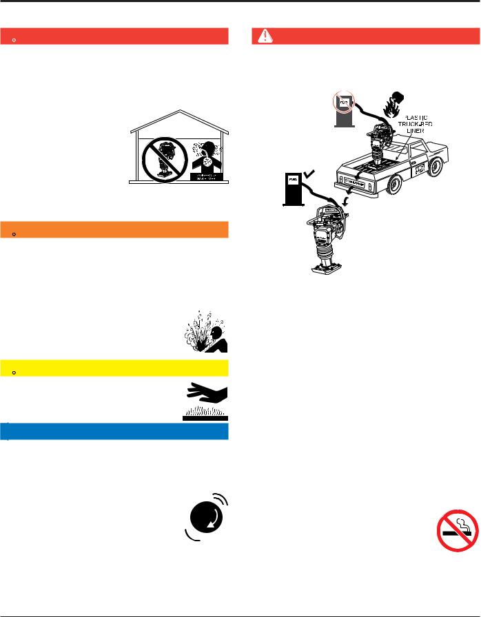
FUEL SAFETY
DANGER
DO NOT add fuel to equipment if it is placed inside truck bed with plastic liner. Possibility exists of explosion or fire due to static electricity.
DO NOT start the engine near spilled fuel or combustible fluids. Fuel is extremely flammable and its vapors can cause an explosion if ignited.
ALWAYS refuel in a well-ventilated area, away from sparks and open flames.
ALWAYS use extreme caution when working with
flammable liquids.
DO NOT fill the fuel tank while the engine is running or hot.
DO NOT overfill tank, since spilled fuel could ignite if it comes into contact with hot engine parts or sparks from the ignition system.
Store fuel in appropriate containers, in well-ventilated areas and away from sparks and flames.
NEVER use fuel as a cleaning agent.
DO NOT smoke around or near the equipment. Fire or explosion could result from fuel vapors or if fuel is spilled on a hot engine.
PAGE 8 — MT75HS RAMMER — OPERATION AND PARTS MANUAL — REV. #11 (01/12/12)

SAFETY INFORMATION
TRANSPORTING SAFETY
 CAUTION
NEVER allow any person or animal to stand underneath the equipment while lifting.
NOTICE
Before lifting, make sure that the equipment parts (hook and vibration insulator) are not damaged and screws are not loose or missing.
Always make sure crane or lifting device has been properly secured to the lifting bail (hook) of the equipment.
ALWAYS shutdown engine before transporting.
NEVER lift the equipment while the engine is running.
Tighten fuel tank cap securely and close fuel cock to prevent fuel from spilling.
Use adequate lifting cable (wire or rope) of sufficient strength.
Use one point suspension hook and lift straight upwards.
DO NOT lift machine to unnecessary heights.
ALWAYS tie down equipment during transport by securing the equipment with rope.
Never allow any person or animal to stand underneath the equipment while lifting.
ENVIRONMENTAL SAFETY
NOTICE
Dispose of hazardous waste properly. Examples of potentially hazardous waste are used motor oil, fuel and fuel filters.
DO NOT use food or plastic containers to dispose of hazardous waste.
DO NOT pour waste, oil or fuel directly onto the ground, down a drain or into any water source.
MT75HS RAMMER — OPERATION AND PARTS MANUAL — REV. #11 (01/12/12) — PAGE 9

GENERAL INFORMATION
Definition of Tamping Rammer
The Mikasa MT-75HS Tamping Rammer is a powerful compacting tool capable of applying a tremendous force in consecutive impacts to a soil surface. Its applications include soil compacting for backfilling for gas pipelines, water pipelines and cable installation work.
The impact force of the MT-75HS levels and uniformly compacts voids between soil particles to increase dry density.
Circular motion is converted to create impact force. The MT75HS tamping rammer develops a powerful compacting force at the foot of the rammer.To maintain optimum performance, proper operation and service are essential.
Construction of Tamping Rammer
The Mikasa MT-75HS is equipped with an Robin air cooled, oilinjected two cycle gasoline engine. Transmission of the power takes place by increasing the engine speed to engage the centrifugal clutch.
Rammer Gearbox and Spring Cylinder
The Mikasa MT-75HS uses an oil bath lubrication system.Always check the oil level through the oil level sight glass at the rear of the tamper foot.
Controls
Before starting the MT-75HS Tamping Rammer identify and understand the function of the controls, see Figure 1 on page11.
PAGE 10 — MT75HS RAMMER — OPERATION AND PARTS MANUAL — REV. #11 (01/12/12)
SPECIFICATIONS
Table1. MT-75HS Rammer Specifications
MODEL |
MT-75HS U.S. (metric) |
|
|
Overall Height |
38.9 in. (990 mm) |
|
|
Overall Width |
16.1 in. (410 mm) |
|
|
Over Length |
29.9 in. (760 mm) |
|
|
Shoe Size |
11.2 X 13.4 in. (285 X 340 mm) |
|
|
Blows/minute |
690 |
|
|
Impact Force |
3200 lbs./blow (1,451 kg/blow) |
|
|
Clutch |
Automatic Centrifugal Clutch |
|
|
Operating Weight |
152 lbs. (69 kg) |
|
|
Table 2. ROBIN EC-12HS Engine Specifications
MODEL |
ROBIN EC-12HS ENGINE |
|
|
Type |
Air-Cooled 2 Stroke Gasoline Engine |
|
|
Piston Displacement |
6.96 cu.in. (114 cc) |
|
|
Max. Output |
4.3 hp/5,000 rpm |
|
|
Max. Governed Speed, No Load |
3,850 rpm |
|
|
Cooling System |
Air-Cooled By Fan |
|
|
Lubrication System |
Fuel-Lubrication Oil Spraying System |
|
|
Fuel |
Gasoline and 2-Stroke oil |
|
|
Starting System |
Recoil Starter |
|
|
NOTE
Specifications are general and are subject to change without notice. If exact measurements are required, equipment should be weighed and measured.
MT75HS RAMMER — OPERATION AND PARTS MANUAL — REV. #11 (01/12/12) — PAGE 11

COMPONENTS
Figure 1. MT-75HS Rammer
Figure 1 shows the location of the controls and components for the MT-75HS Tamping Rammer. The functions of each control is described below:
1.Throttle Lever – Controls engine speed and the tamping action of the rammer.
2.EngineStopSwitch–Controls the starting and stopping of the engine. Switch must be in the "ON" position when starting the engine.
3.ChokeLever– Usedwhenstartingtheengine.Normally used in cold weather conditions. In cold weather turn the choke lever to the fully closed position, in warm weather set choke lever half way or completely open.
4.Fuel Shut-OffValve – Supplies fuel from the fuel tank to the engine.To begin fuel flow move the fuel shut-off valve downward.
5.Oil Bath Fill Plug – Open this plug to add oil to the oil bath reservoir.
6.Drain Valve – Open this valve to remove oil from the bellows.
7. PreCleaner – Pre-cleans (first stage) dirt and other debris from entering the engine.
8.Foot– Laminated wood with tempered steel plate for superior shock absorption.
8.Foot– Laminated wood with tempered steel plate for superior shock absorption.
9.Oil Level Sight Glass – Indicates the level of oil in the oil bath reservoir.
10.RecoilStartingHandle–Usedwhenstartingtheengine.
Pull starter handle sharply and quickly, then return starter handle to starter case before releasing.
11.Fuel Tank/Cap – Poly fuel tank to avoid rust and corrosion, remove this cap to add gasoline.
12.Engine Air Cleaner – Prevents dirt (second stage) and other debris from entering the engine.
13.Bellows – Reservoir for oil bath.
14.Handle – To operate rammer GRIP handle assembly firmly on both sides.
15.Muffler– Used to reduce noise and emissions.
16.Spark Plug – Provides spark to the ignition system, replace with engine manufactures recommended type spark plug.
17.NamePlate– Displaysinformationregardingtherammer.
18.Roller Bar – Used when transporting rammer onto a truck bed. Place rammer on this roller bar then slide.
19.Oil Tank – Fill oil tank with 2-stroke motor oil.
PAGE 12 — MT75HS RAMMER — OPERATION AND PARTS MANUAL — REV. #11 (01/12/12)
OPERATION
This section is intended to assist the operator with the initial start-up of the MT-75HSTamping Rammer.It extremely important that this section be read carefully before attempting to operate the rammer.
DO NOT use your rammer until this section is thoroughly understood.
CAUTION:
Failure to understand the operation of the MT75HS Tamping Rammer could result in severe damage to the trowel or personal injury.
Rammer Gearbox and Spring Cylinder Oil Bath
This unit uses an oil bath lubrication system.Perform the following:
1.Checktheoillevelthroughtheoillevelsightglass(Figure2) at the rear of the tamper foot.
Engine
1.Fill the fuel tank (Figure 3 ) with unleaded gasoline. At the same time, check the engine oil level at the sight gauge located on the operator's side of the oil tank. Fill the oil tank tothe"H"levelusingonlyoutboard(2-stroke)oil. Replenish theoilregularlybeforetheoillevelreachesthe"L"levelofthe oil tank.
CAUTION:
The oil hose is not to be depressed or damaged. A sensor detects lack of oil and shuts down the engine automatically.
Figure 2. Foot Housing Sight Glass
2.If oil is not visible, add 10W-30 motor oil into the oil fill plug opening (Figure 2). The bath contains approximately 1.7 pints (800 cc.)
NOTE
The oil level should be kept at the half way point of the sight glass.
CAUTION:
Failure to understand the operation of the MT60HSTamping Rammer could result in severe damage to the rammer or personal injury.
Figure 3. Fuel/Oil Tank
2. Low levels of oil may result in engine seizure due to high levels of consumption during operations.
3. Check the engine oil level (Figure 4) and if the oil level is low, it should be refilled. Use the proper motor oil as suggested in Table 3 .
Figure 4. Engine Oil Dipstick
Table 3. Motor Oil Grade
Season or Temperature |
Grade of motor oil |
|
(higher than MS class) |
||
|
||
|
|
|
Spring, Summer or Autumn |
SAE 30 |
|
+120° F to +15° F |
||
|
||
|
|
|
Winter |
SAE 30 |
|
+40° F to +15° F |
||
|
||
|
|
|
Below +15° F |
SAE 10W-30 |
|
|
|
MT75HS RAMMER — OPERATION AND PARTS MANUAL — REV. #11 (01/12/12) — PAGE 13

OPERATION
Inspection
1. Check all nuts, bolts fasteners for tightness. Retighten as necessary.
2.Clean anydirtfromtherecoil starterand footpedestal. Wipe the entire unit clean before operating.
3.ReplaceanymissingordamagedSafetyOperationdecals.
4.Adjustheightofhandle.Adjusthandlebylooseningnutsand moving handle to suit operation. Retighten nuts.
Initial Start-up
When starting the MT-75HS Tamping Rammer perform the following:
1.Open the fuelshutoff valveby moving the fuel cock lever to the open position (Figure 5).
Figure 5. Fuel Cock and Choke Lever
3.Close the choke lever (Figure 5) . Turning the choke lever 90degreesclockwiseclosesthechoke.Incoldweather,start theunitwithchokefullyclosed.Inwarmweatherorwhenthe engine is warm, the unit can be started with choke halfway or completely open.
4.Movethethrottlelever(Figure7)between1/4to1/2fromthe idle position.
Figure 7. Throttle Lever (1/4 to 1/2)
4.Grip the recoil starter (Figure 8) handle and pull it until you feelaslightresistance. Thenpullsharplyandquickly. Return therecoilstarterhandletothestarterpositionbeforereleasing.
2.Set the engine ON/OFF switch (Figure 6) to the "ON" position(start).
Figure 6. Engine On/Off Switch
Figure 8. Recoil Starter
5.Ifenginefailstostart,movethechokelever(Figure 5) tothe half open position to avoid flooding.
6.Repeat steps 1 thru 5.
7.If the engine does not start after repeated attempts, check the spark plug for excess fuel. Clean and replace the spark plug as needed.
PAGE 14 — MT75HS RAMMER — OPERATION AND PARTS MANUAL — REV. #11 (01/12/12)

OPERATION
7.If the carburetor is flooded or the crankcase is loaded with excess fuel, open the drain plug as shown in (Figure 9) and drain out excess fuel.
Figure 9. Drain Plug
Operation
1.To start the rammer tamping action, move the throttle lever (Figure 10) quickly from IDLE (close) to the FULL OPEN position.DONOT movethethrottleleverslowlyasthismay cause damage to the clutch or spring.
CAUTION:
Make sure that the throttle lever is moved to the FULL OPEN position. Operating the rammer at less than full speeds can result in damage to the clutch springs or foot.
Figure 10. Throttle Lever (Full Open)
2.The MT-75HS Tamping rammer is designed to run at 5,000 rpm. At optimum rpmthefoot hitsat the rateof690impacts per minute. Increasing throttle speed past factory set rpm does not increase impacts and may damage unit.The MT75HS is designed to advance while tamping. For faster advance, pull back slightlyon the handle so that rear of foot contactssoilfirst.
Stopping The Engine
Normal Shutdown
1.Move throttle lever quickly from the FULL OPEN to IDLE position (Figure 11) and run the engine for three minutes at lowspeed.Aftertheenginecools,turntheenginestart/stop switch to the “OFF” position (Figure 6) until engine comes to a complete stop.
Figure 11. Throttle Lever (Idle)
2.Closethefuelshut-offvalvebymovingthefuelcockleverto the CLOSED position. See Figure 5
Emergency Showdown
1.Movethethrottleleverquicklytothe IDLE position,andturn theenginestart/stopswitch(Figure6) totheSTOPposition.
MT75HS RAMMER — OPERATION AND PARTS MANUAL — REV. #11 (01/12/12) — PAGE 15
 Loading...