


PARTS AND OPERATION MANUAL
© COPYRIGHT 2002, MULTIQUIP INC.
Model KD1800/KD6
A.C. GENERATOR
USED WITH MLT SERIES MODULAR LIGHT TOWERS
Revision #1 (06/16/05)
MULTIQUIP INC. |
PARTS DEPARTMENT: |
18910 WILMINGTON AVE. |
800-427-1244 |
CARSON, CALIFORNIA 90746 |
FAX: 800-672-7877 |
310-537-3700 |
SERVICE DEPARTMENT/TECHNICAL ASSISTANCE: |
800-421-1244 |
800-478-1244 |
FAX:310-537-3927 |
FAX:310-631-5032 |
E-mail:mq@multiquip.com • www:multiquip.com
Atlanta • Boise • Dallas • Houston • Newark
Montreal, Canada • Manchester, UK
Rio De Janiero, Brazil • Guadalajara, Mexico
P/N 29309
PAGE 2 —KD1800/KD6 A.C. GENERATOR— PARTS & OPERATION MANUAL — REV. #1 (06/16/05)
HERE'S HOW TO GET HELP
PLEASE HAVE THE MODEL AND SERIAL NUMBER ON-HAND WHEN CALLING
PARTS DEPARTMENT
800-427-1244 or 310-537-3700 FAX: 800-672-7877 or 310-637-3284
SERVICE DEPARTMENT/TECHNICAL ASSISTANCE
800-478-1244 or 310-537-3700 FAX: 310- 537-4259
WARRANTY DEPARTMENT
888-661-4279, or 310-661-4279 FAX: 310- 537-1173
MAIN
800-421-1244 or 310-537-3700 FAX: 310-537-3927
KD1800/KD6 A.C. GENERATOR — PARTS & OPERATION MANUAL — REV. #1 (06/16/05) — PAGE 3

Here's How To Get Help ............................................ |
3 |
Table Of Contents ..................................................... |
4 |
Parts Ordering Procedures ....................................... |
5 |
Safety Alert Message Symbols .............................. |
6-7 |
Rules For Safe Operation ...................................... |
8-9 |
Operation and Safety Decals ............................. |
10-11 |
Generator Specifications ........................................ |
12 |
Engine Specifications .............................................. |
13 |
General Information ................................................ |
14 |
Multiquip KD1800/KD6 |
|
AC Generator |
|
Dimension ............................................................... |
15 |
Controls and Indicators ...................................... |
16-17 |
Installation ............................................................... |
18 |
Pre-Setup (Generator) ....................................... |
19-20 |
Pre-Setup (Engine) ............................................ |
21-22 |
Instrumentation ....................................................... |
23 |
Load Application ..................................................... |
24 |
Engine Operating Instructions ................................ |
25 |
Maintenance (Engine)........................................ |
26-27 |
Maintenance (Generator) ....................................... |
30 |
Preparation For Long Term Storage ....................... |
31 |
Troubleshooting (Generator) .................................. |
32 |
Troubleshooting (Engine) ................................... |
33-34 |
Explanation Of Codes In Remarks Column ............ |
36 |
Suggested Spare Parts ........................................... |
37 |
Nameplate and Decals....................................... |
38-39 |
Enclosure Assy................................................... |
40-41 |
Control Box Assy. ............................................... |
42-43 |
Engine Mounting Hardware Assy. ...................... |
44-45 |
Radiator Assy. .................................................... |
46-47 |
Air Cleaner and Muffler Assy. ............................ |
48-49 |
Battery Assy. ...................................................... |
50-51 |
Drain Plug Assy. ................................................. |
52-53 |
Fuel Assy............................................................ |
54-55 |
Generator Assy. ................................................. |
56-57 |
Control Box Wiring Diagram.................................... |
58 |
Generator Wiring Diagram ...................................... |
59 |
Engine Wiring Diagram ........................................... |
60 |
NOTE
Specification and part number are subject to change without notice.
TABLE OF CONTENTS
Kubota D905EBG-2 Engine
Crankcase Assembly ......................................... |
62-63 |
Oil Pan Assembly ............................................... |
64-65 |
Cylinder Head Assembly .................................... |
66-67 |
Gear Case Assembly ......................................... |
68-69 |
Head Cover Assembly ....................................... |
70-71 |
Oil Filter Assembly ............................................. |
72-73 |
Dipstick and Guide Assembly ............................ |
74-75 |
Main Bearing Case Assembly ............................ |
76-77 |
Camshaft and Idle Gear Shaft Assembly........... |
78-79 |
Piston and Crankshaft Assembly ....................... |
80-81 |
Flywheel Assembly ............................................ |
82-83 |
Fuel Camshaft and Governor Shaft Assembly ..84-85 |
|
Engine Stop Lever Assembly ............................. |
86-87 |
Stop Solenoid Assembly .................................... |
88-89 |
Injection Pump Assembly ................................... |
90-91 |
Injection Pump (Component Parts) Assembly |
...92-93 |
Governor ............................................................ |
94-95 |
Speed Control Plate Assembly .......................... |
96-97 |
Nozzle Holder and Glow Plug Assembly............ |
98-99 |
Nozzle Holder (Component Parts) Assy. ...... |
100-101 |
Fuel Pump Assembly (Mechanical) .............. |
102-103 |
Alternator and Pulley Assembly .................... |
104-105 |
Alternator (Component Parts) Assembly ...... |
106-107 |
Starter Assembly .......................................... |
108-109 |
Starter (Component Parts) Assembly.......... |
110-111 |
Oil Switch/Thermometer and Plug Assembly 112-113 |
|
Water Flange and Thermostat Assembly...... |
114-115 |
Water Pump Assembly .................................. |
116-117 |
Water Pipe Assembly .................................... |
118-119 |
Fan Assembly................................................ |
120-121 |
Valve and Rocker Arm Assembly .................. |
122-123 |
Inlet Manifold Assembly ................................ |
124-125 |
Exhaust Manifold Assembly .......................... |
126-127 |
Accessories and Service Parts Assembly ..... |
128-129 |
Label and Operator's Manual ....................... |
130-131 |
Terms and Conditions Of Sale — Parts ................ |
132 |
PAGE 4 —KD1800/KD6 A.C. GENERATOR— PARTS & OPERATION MANUAL — REV. #1 (06/16/05)
PARTS ORDERING PROCEDURES
■Dealer account number
■Dealer name and address
■Shipping address (if different than billing address)
■Return fax number
■Applicable model number
■Quantity, part number and description of each part
■Specify preferred method of shipment:
•UPS Ground
•UPS Second Day or Third Day*
•UPS Next Day*
•Federal Express Priority One (please provide us with your Federal Express account number)*
•Airborne Express*
•Truck or parcel post
*Normally shipped the same day the order is received, if prior to 2PM west coast time.
Earn Extra Discounts when you order by FAX!
All parts orders which include complete part numbers and are received by fax qualify for the following extra discounts:
Number of |
|
line items ordered |
Additional Discount |
1-9 items |
3% |
10+ items** |
5% |
Get special freight allowances when you order 10 or more line items via FAX!**
■UPS Ground Service at no charge for freight
■UPS Third Day Service at one-half of actual freight cost
No other allowances on freight shipped by any other carrier.
**Common nuts, bolts and washers (all items under $1.00 list price) do not count towards the 10+ line items.
*DISCOUNTS ARE SUBJECT TO CHANGE*
Fax order discount and UPS special programs revised June 1, 1995
Extra |
Fax |
Discount |
||||
|
|
USA |
||||
|
|
|
||||
for |
Domestic |
|
||||
Dealers |
Only |
|||||
|
||||||
|
|
|
||||
Now! Direct TOLL-FREE access to our Parts Department!
Toll-free nationwide:
800-421-1244
Toll-free FAX:
800/6-PARTS-7 • 800-672-7877
KD1800/KD6 A.C. GENERATOR — PARTS & OPERATION MANUAL — REV. #1 (06/16/05) — PAGE 5
KD1800/KD6 — SAFETY MESSAGE ALERT SYMBOLS
FORYOUR SAFETY AND THE SAFETY OF OTHERS!
Safety precautions should be followed at all times when operating this equipment. Failure to read and understand the Safety Messages and Operating Instructions could result in injury to yourself and others.
NOTE
This Owner's Manual has been developed to provide complete instructions for the safe and efficient operation of the MQ Whiteman Model KD1800/KD6 6KW Generator. Please refer to the engine manufacturers instructions for data relative to its safe operation.
Before using this Generator, ensure that the operating individual has read and understands all instructions in this manual.
SAFETY MESSAGE ALERT SYMBOLS
The three (3) Safety Messages shown below will inform you about potential hazards that could injure you or others. The Safety Messages specifically address the level of exposure to the operator, and are preceded by one of three words: DANGER,
WARNING, or CAUTION.
DANGER: You WILL be KILLED or SERIOUSLY injured if you DO NOT follow directions.
WARNING: You CAN be KILLED or SERIOUSLY injured if you DO NOT follow directions.
CAUTION: You CAN be injured if you
DO NOT follow directions.
Potential hazards associated with KD-1800/KD-6 Generator operation will be referenced with Hazard Symbols which appear throughout this manual, and will be referenced in conjunction with Safety Message Alert Symbols.
HAZARD SYMBOLS
Lethal Exhaust Gases
Engine exhaust gases contain poisonous carbon monoxide. This gas is colorless and odorless, and can cause death if inhaled. NEVER operate this equipment in a confined area or enclosed structure that does not provide ample free flow air.
Explosive Fuel
Diesel fuel is extremely flammable, and its vapors can cause an explosion if ignited. DO NOT start the engine near spilled fuel or combustible fluids. DO NOT fill the fuel tank while the engine is running or hot. DO NOT overfill tank, since spilled fuel could ignite if it comes into contact with hot engine parts or sparks from the ignition system. Store fuel in approved containers, in well-ventilated areas and away from sparks and flames. NEVER use diesel fuel as a cleaning agent.
Burn Hazards
Engine components can generate extreme heat. To prevent burns, DO NOT touch these areas while the engine is running or immediately after operations. NEVER operate the engine with heat shields or heat guards removed.
Rotating Parts
NEVER operate equipment with covers, or guards removed. Keep fingers, hands, hair and clothing away from all moving parts to prevent injury.
PAGE 6 —KD1800/KD6 A.C. GENERATOR— PARTS & OPERATION MANUAL — REV. #1 (06/16/05)
KD1800/KD6 — SAFETY MESSAGE ALERT SYMBOLS
Accidental Starting |
|
|
|
Sight and Hearing hazard |
|
|
|
|
ALWAYS place the ignition switch in the OFF position, remove key when the equipment is not in use. Store key in a safe place.
Over Speed Conditions
ALWAYS wear approved eye and hearing protection.
Equipment Damage Messages
NEVER tamper with the factory settings of the engine governor or settings. Personal injury and damage to the engine or equipment can result if operating in speed ranges above maximum allowable.
Other important messages are provided throughout this manual to help prevent damage to your generator, other property, or the surrounding environment.
NOTE
This generator, other property, or the surrounding environment could be damaged if you DO NOT follow instructions.
KD1800/KD6 A.C. GENERATOR — PARTS & OPERATION MANUAL — REV. #1 (06/16/05) — PAGE 7

KD1800/KD6 — RULES FOR SAFE OPERATION
CAUTION:
Failure to follow instructions in this manual may lead to serious injury or even death! This equipment is to be operated by trained and qualified personnel only! This equipment is for industrial use only.
The following safety guidelines should always be used when operating the KD1800/KD6 6 KW AC
Generator:
GENERAL SAFETY
■DO NOT operate or service this equipment beforereadingthisentiremanual.
■This equipment should not be operated by persons under 18 years of age.
■NEVER operate this equipment without proper protective clothing, shatterproof glasses, steel-toed boots and other protective devices required by the job.
■NEVER operate this equipment when not feeling well due to fatigue, illness or taking medicine.
■NEVER operate this equipment under the influence or drugs or alcohol.
■NEVER use accessories or attachments, which are not recommended by Multiquip for this equipment. Damage to the equipment and/or injury to user may result.
■Manufacture does not assume responsibility for any accident due to equipment modifications.
■Whenever necessary, replace nameplate, operation and safety decals when they become difficult read.
■ALWAYS check the machine for loosened threads or bolts before starting.
■NEVER touch the hot exhaust manifold, muffler or cylinder. Allow these parts to cool before servicing engine or generator.
■HighTemperatures – Allow the engine to cool before adding fuel or performing service and maintenance functions. Contact with hot components can cause serious burns.
■The engine of this generator requires an adequate free flow of cooling air. NEVER operate the generator in any enclosed
or narrow area where free flow of the air is restricted. If the air flow is restricted it will cause serious damage to the generator engine and may cause injury to people. Remember the generator's engine gives off DEADLY carbon monoxide gas.
■ALWAYS refuel in a well-ventilated area, away from sparks and open flames.
■ALWAYS use extreme caution when working with flammable liquids. When refueling, stop the engine and allow it to cool.
■NEVER smoke around or near the machine. Fire or explosion could result from fuel vapors, or if fuel is spilled on a hot engine.
■NEVER operate the generator in an explosive atmosphere or near combustible materials. An explosion or fire could result causing severe bodily harm or even death.
■Topping-off to filler port is dangerous, as it tends to spill fuel.
PAGE 8 —KD1800/KD6 A.C. GENERATOR— PARTS & OPERATION MANUAL — REV. #1 (06/16/05)
KD1800/KD6 — RULES FOR SAFE OPERATION
■DO NOT operate or service this equipment before reading this entire manual.
■This equipment should not be operated by persons under 18 years of age.
■NEVER operate this equipment without proper protective clothing, shatterproof glasses, steel-toed boots and other protective devices required by the job.
■This generator is a source of providing LETHAL high voltages. NEVER permit unqualified personnel-especially children to operate the generator.
■ALWAYS refuel in a well-ventilated area, away from sparks and open flames.
■ALWAYS use extreme caution when working with flammable liquids. When refueling, stop the engine and allow it to cool. DO NOT smoke around or near the machine. Fire or explosion could result from flames or sparks, or if fuel is spilled on a hot engine.
■This generator is equipped with a ground terminal for your protection. ALWAYS complete the grounding path from the generator to an external grounding source.
■NEVER operate this generator, or handle any electrical equipment while standing in water, while bare foot, while hands are wet, or in the rain. Dangerous electrical shock could occur causing severe bodily harm or even death.
■Keep electrical cords in good condition. Worn, bare or frayed wiring can cause electrical shock, thus causing bodily harm or even death.
■This generator requires an adequate free flow of cooling air. NEVER operate the generator in any enclosed or narrow area where free flow of the air is restricted. If the air flow is restricted it will cause serious damage to the generator and may cause injury to people.
■NEVER touch the hot exhaust manifold, muffler or cylinder. Allow these parts to cool before servicing generator.
■Provide adequate ventilation when operating the generator. DO NOT operate the generator in any enclosed or narrow space. The gasoline engine that provides power to the generator gives off DEADLY monoxide gas.
■NEVER operate the generator in an explosive atmosphere or near combustible materials. An explosion or fire could result causing severe bodily harm or even death.
■ALWAYS make sure that the generator is secure on level ground so that it cannot slide or shift around, endangering workers. Also keep the immediate area free of bystanders.
■HighTemperatures – Allow the machine and engine to cool before adding fuel or performing service and maintenance functions. Contact with hot components can cause serious burns.
CAUTION:
Emergencies
■ ALWAYS know the location of the nearest fire extinguisher and first aid kit. Know the location of the nearest telephone. Also know
the phone numbers of the nearest ambulance, doctor and fire department. This information will be invaluable in the case of an emergency.
Maintenance Safety
■NEVER lubricate components or attempt service on a running machine.
■ALWAYS allow the machine a proper amount of time to cool before servicing.
■Keep the machinery in proper running condition.
■Fix damage to the machine immediately and always replace broken parts.
■Dispose of hazardous waste properly.Examples of potentially hazardous waste are used motor oil, fuel and fuel filters.
■DO NOT use plastic containers to dispose of hazardous waste.
■DO NOT pour waste, oil or fuel directly onto the ground, down a drain or into any water source.
KD1800/KD6 A.C. GENERATOR — PARTS & OPERATION MANUAL — REV. #1 (06/16/05) — PAGE 9
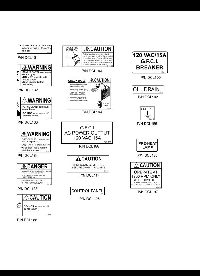
KD1800/KD6 — OPERATION AND SAFETY DECALS
Machine Safety Decals
The KD1800/KD6 generator is equipped with a number of safety decals. These decals are provided for operator safety and maintenance information.The illustration below shows these decals as they appear on the machine. Should any of these decals become unreadable, replacements can be obtained from your dealer. For a complete decal sheet order P/N 29345.
PAGE 10 —KD1800/KD6 A.C. GENERATOR— PARTS & OPERATION MANUAL — REV. #1 (06/16/05)

KD1800/KD6 — OPERATION AND SAFETY DECALS
KD1800/KD6 A.C. GENERATOR — PARTS & OPERATION MANUAL — REV. #1 (06/16/05) — PAGE 11

KD1800/KD6 — GENERATOR SPECIFICATIONS
TABLE 1. |
GENERATOR SPECIFICATIONS |
|
|
|
|
Model |
|
Marathon 332CSA5203 |
|
|
|
Phase |
|
Single Phase |
|
|
|
Maximum Output |
|
6,000 Watts |
|
|
|
Continious Output |
|
6,000 Watts |
|
|
|
Rated Voltage |
|
120/240 Volts |
|
|
|
Amps at 120/240 |
|
50/25 Amps |
|
|
|
Frequency |
|
60 Hz. |
|
|
|
Speed |
|
1,800 rpm |
|
|
|
Dry Weight1 |
|
110 lbs. (50 Kg.) Generator Only |
|
|
|
Dry Weight2 |
|
702 lbs (305 Kg.) Complete |
|
|
|
1.This weight is for the generator only. It DOES NOT include the cabinet.
2.This weight is for a complete generator, which includes the engine, radiator and cabinet enclosure.
PAGE 12 —KD1800/KD6 A.C. GENERATOR— PARTS & OPERATION MANUAL — REV. #1 (06/16/05)

KD1800/KD6 — GENERATOR SPECIFICATIONS
TABLE 2. ENGINE SPECIFICATIONS |
||
|
|
|
Model |
KUBOTA D905-EBG-2E |
|
|
|
|
Rated Output (Gross Intermittent) Power |
13.7 HP @1,800 rpm's |
|
23.0 HP @3,000 rpm's |
||
|
||
|
|
|
Net Continous Power |
10.2 HP @1,800 rpm's |
|
17.0 HP @3,000 rpm's |
||
|
||
|
|
|
Displacement |
54.80 cu. in (898 cm2) |
|
|
|
|
Combustion Chamber |
Spherical Type (9E-TVCS) |
|
|
|
|
Maximum Bare Idle Speed |
3,800 rpm's |
|
|
|
|
Number of Cylinders |
3 |
|
|
|
|
Cooling System |
Water-Cooled |
|
|
|
|
Fuel Tank Capacity* |
30 gal. (113 liters) |
|
|
|
|
Run Time, 3/4 Load |
56 hours |
|
|
|
|
Fuel Type |
Diesel No.2-D (ATSM D975) |
|
|
|
|
Coolant Capacity Radiator |
0.82 gal (3.1 liters) |
|
|
|
|
Coolant Capacity Reserve Tank |
0.158 gal (0.6 liters) |
|
|
|
|
Lube Oil capacity |
1.34 gal (5.1 liters) |
|
|
|
|
Lubricant (API Classification) |
Above CD Grade |
|
|
|
|
Battery |
12V-40Ah |
|
|
|
|
Dimensions (L x W x H) |
19.60 x 15.59 x 23.96 in |
|
(497.8 x 396 x 608.7 mm) |
||
|
||
|
|
|
Weight |
205 lbs. (93 kg.) |
|
|
|
|
*Fuel tank is part of Modular Light Tower (MLT) trailer.
The maximum output of the engine listed above is applicable to supplying electrical power for continuous service at ambient conditions in accordance with SAE Test cord J607. The above ambient conditions are at standard sea level, with a barometric reading of 29.92 inches and a temperature of 60 degrees Fahrenheit.
Generally, the engine output power will decrease 3 1/2% for each 1000 feet of altitude above sea level, and 1% for each 10° F Fahrenheit above the standard temperature of 60° F
KD1800/KD6 A.C. GENERATOR — PARTS & OPERATION MANUAL — REV. #1 (06/16/05) — PAGE 13
KD1800/KD6 — GENERAL INFORMATION
KD1800/KD6 FAMILIARIZATION
Generator
Housed within the KD1800/KD6 generator package is a Marathon Model 332, 6,000 watt (6-KW) generator. This generator can provide up to 50 amps of current. In addition two voltage output receptacles have been provided on the generator's control box. One receptacle has an output of 120/250 VAC and the other is a 120 VAC, GFCI protected receptacle.
The Marathon Model 332 generator should only be operated at a frequency of 60 hertz.The speed should be 1,850 rpm's (no load) and 1,800 rpm's (full load). A single capacitor is used to regulate the voltage to within 5% of the rated load.
The engine-generator set must be installed in a protected environment, with a minimal exposure to fumes, moisture, dust and dirt.
NOTE
When operating the generator, remember the outside air temperature must not exceed
40°C (104°F).
Remember the following when using the generator:
zDO NOT obstruct the generator's intake and outlet passages.
zALWAYS provide sufficient air circulation around the generator to remove engine heat and to provide ample generator cooling.
zHOT AIR from the radiator must not enter into the generator.
zUse extreme caution when handling capacitors. A potential shock condition exist even when the engine has been shut-off. See maintenance section of this manual for the proper handling of capacitors.
zFor operation at high altitudes, ratings must be derated 2% for each 1000 feet above sea level.
zFrame temperatures above 60° C (104° F) are too high,
indicating a temperature rise in the copper windings of 105°C (122° F) or more.
zAfter running the generator for 30 minutes at full load check the temperature rise. If the temperature is excessive, examine the generator for the following:
A.Obstructed air-flow
B.Hot air feeding into the inlet of the generator.
C.By-passed air (air not pulled through generator)
Control Panel
The generator's control box is provided with the following components:
zOne Duplex GFCI 120 VAC Receptacle, 15 Amps
zOne 120/250 VAC receptacle, 30 Amps
zMain Circuit Breaker 240 V @30 Amps
zGFCI Circuit Breaker 120 V @15 Amps
zPre-Heat Lamp Indicator
zIgnition Switch
Engine
The KD1800/KD6 is powered by vertical, water-cooled, 4- cycle diesel engine. This engine is designed to meet every performance requirement for the generator.
ALWAYS perform a maintenance check list before starting the engine.
Reference Tables 1 and 2 for generator and engine specifications.
Refer to the engine maintenance section for more information about the engine.
Figure 2 (page 16) shows the basic components and indicators for the KD1800/KD6 generator.
NOTE
In keeping with Multiquip's policy of constantly improving its products, the specifications quoted herein are subject to change without prior notice.
PAGE 14 —KD1800/KD6 A.C. GENERATOR— PARTS & OPERATION MANUAL — REV. #1 (06/16/05)
KD1800/KD6 — DIMENSIONS
Figure 1. KD1800/KD6 Dimensions
KD1800/KD6 A.C. GENERATOR — PARTS & OPERATION MANUAL — REV. #1 (06/16/05) — PAGE 15
KD1800/KD6 — CONTROLS AND INDICATORS
PAGE 16 —KD1800/KD6 A.C. GENERATOR— PARTS & OPERATION MANUAL — REV. #1 (06/16/05)

KD1800/KD6 — CONTROLS AND INDICATORS
Figure 2 shows the location of the controls and indicators of the KD1800/KD6 generator.The functions of each control or indicator is described below:
1.Radiator Filler Port – Remove this plate to add coolant (anti-freeze) to the radiator. NEVER add coolant to the radiator when the radiator is HOT!. Allow the radiator to cool before adding coolant. Use a water coolant mixture as recommended in the maintenance section of this manual.
2.Air Outlet Exhaust Pipe – Allows engine exhaust to exit the generator into the open air.NEVER block this opening.
3.Muffler– Used to reduce noise and emissions.
4.Lifting Hook – Use this hook to lift the generator. ALWAYS use a lifting device of adequate lifting capacity to lift the generator.
16.BatteryTerminals – Connect these terminals to the battery. Always pay close attention to the polarity of the terminals when connecting to the battery,RED (positive), and BLACK (negative).
17.Fuel Filter – Prevents dirt and foreign debris from entering the fuel system. Replace this filter as recommended in the maintenance section of this manual.
18.Engine Oil Filler Port – Remove this cap to add engine oil. Use only recommended type oil. See table 3.
19.Battery – Provides +12VDC power for the generator.When replacing battery (12V 40 AH) use only recommended type battery.
20.Air Inlet vent – Allows outside air to enter the generator. NEVER block this opening.
5.Oil Drain Plug – Remove this plug to drain oil from the 21. Engine Oil Dipstick – Remove this dipstick to determine
engine crankcase. Fill with recommended type oil as specified in the maintenance section of this manual.
6.Engine Air Cleaner – Prevents dirt and other debris from entering the fuel system. Lift locking latch on air filter cannister to gain access to filter element.
7.Marathon Generator – Provides single-phase AC power for external equipment. See specification table (Table 1) within this manual.
the level of the oil in the engine crankcase. For safe engine operation always maintain the oil between the two notches on the dipstick. Add recommended type engine oil as specified in Table 4.
22.Oil Filter – Provides oil filtering for the engine. Replace with only recommended type oil filter.
23.Primer Bulb – Removes air from the fuel system in the event the engine has run out of gas.
8.Generator Output Box – Contains the excitation 24. Overflow Bottle – Supplies coolant to the radiator when
electronics for the generator.
9.Generator Mounting Hardware – Use this hardware to install or remove the generator from the trailer frame.
10.Receptacle G.F.C.I. – Provides 120 volts output at 15 amps.
11.Circuit Protector Circuit Breaker – This single pole circuit breaker provides circuit protection (120V @15 amps) for the G.F.C.I receptacle.
12.Main Circuit Breaker – This 2-pole circuit breaker provides circuit protection (120/240V @30 amps) for the load side of the generator.
13.Hour Meter – Indicates number of hours machine has been in use or hours engine was run.
14.Ignition Switch – With key inserted turn clockwise to start engine.
15.Pre-Heat Indicator Light – Lights blue during engine start-up. Indicates that engine glow plugs are being preheated. Light will go off after approximately 10 seconds.
radiator coolant level is low.Fill to indicated level as shown on bottle
25.Cabinet Latch – Use this latch to keep cabinet door open.
26.Documentation Box – Operation, parts and service manuals are kept in this box.
27.Cabinet Handle – Turn handle clockwise to release locking mechanism, then pull cabinet door upward to gain access to engine compartment.
28.Output Receptacle – Remove cover plate to gain access to receptacle. To receive power from the generator, plug external power cable into this receptacle.
29.Frame Ground Lug – Connect a ground strap between this lug and a ground rod. Make sure that the ground rod is inserted deep into the ground to provide a good earth ground. Consult with local Electrical and Safety Codes for proper connection.
KD1800/KD6 A.C. GENERATOR — PARTS & OPERATION MANUAL — REV. #1 (06/16/05) — PAGE 17

Outdoor Installation
Install the generator in a location where it will not be exposed to rain or sunshine. Make sure that the welder/generator is on secure level ground so that it cannot slide or shift around. Also install the generator in a manner so that the exhaust will not be discharged in the direction of nearby homes.
The installation site must be relatively free from moisture and dust. All electrical equipment should be protected from excessive moisture. Failure to do will result in deterioration of the insulation and will result in short circuits and grounding.
Foreign materials such as dust, sand, lint and abrasive materials have a tendency to cause excessive wear, not only to the engine parts, but also to the alternator parts.
CAUTION :
Pay close attention to ventilation when operating the generator inside tunnels and caves. The engine exhaust contains noxious elements.
KD1800/KD6 — INSTALLATION
Indoor Installation
Exhaust gases from diesel engines are extremely poisonous.
Whenever an engine is installed indoors the exhaust fumes must be vented to the outside.The engine should be installed at least two feet from any outside wall. Using an exhaust pipe which is too long or too small can cause excessive back pressure which will cause the engine to heat excessively and possibly burn the valves.
Eliminate the danger of deadly carbon monoxide gas. Remember that exhaust fumes from any gasoline engine are very poisonous if discharged in a closed room, but harmless if allowed to mix with the outside air.If the generator is installed indoors, you must make provisions for venting the engine exhaust to the outside of the building.
PAGE 18 —KD1800/KD6 A.C. GENERATOR— PARTS & OPERATION MANUAL — REV. #1 (06/16/05)
KD1800/KD6 — PRE-SETUP (GENERATOR)
General Inspection Prior to Operation
The KD1800/KD6 utilizes a generator that has been thoroughly inspected and accepted prior to shipment from the factory. However, be sure to check for damaged parts or components, or loose nuts and bolts, which could have occurred in transit.
Generator Grounding
To guard against electrical shock and possible damage to the equipment, it is important to provide a good EARTH ground.
Article 250 (Grounding) of the National Electrical Code (NEC) provides guide lines for proper grounding and specifies that the cable ground shall be connected to the grounding system of the building as close to the point of cable entry as practical. If a building is not accessible, then the use of a ground rod is sufficient.
NOTE
Check local city codes for proper grounding requirements.
NEC articles 250-91a and 250-95 sets the following grounding requirements:
1.Use one of the following wire types to connect the generator to earth ground.
a.Copper - 10 AWG (5.3 mm2) or larger.
b.Aluminum - 8 AWG (8.4 mm2) or larger.
2.The ground terminal on the generator should always be used to connect the generator to a suitable ground.The ground ring on the generator (Figure 3) should be able to accommodate #8 size copper or aluminum wire.
3.Crimp the ground wire to the ground lug on the generator. Connect the other end of the ground wire to a suitable building ground or ground rod.
4.NEC article 250-83c specifies that the earth ground rod should be buried a minimum of 8 ft. into the ground.
NOTE
When connecting the generator to any buildings electrical system ALWAYS consult with a licensed
Figure 3. Generator Grounding
Configuration
KD1800/KD6 A.C. GENERATOR — PARTS & OPERATION MANUAL — REV. #1 (06/16/05) — PAGE 19

KD1800/KD6 — PRE-SETUP (GENERATOR)
Circuit Breakers
To protect the generator from an overload, a 2-pole, 30 amp, main circuit breaker is provided. In addition a single pole, 15 amp breaker is provided for the G.F.C.I. receptacle. Make sure to switch both circuit breakers to the "OFF" position prior to starting the engine.
Extension Cable
When electric power is to be provided to various tools or loads at some distance from the generator, extension cords are normally used. Cables should be sized to allow for distance in length and amperage so that the voltage drop between the generator and point of use (load) is held to a minimum. Use the cable selection chart (Table 3 ) as a guide for selecting proper cable size.
Table 3. Extension Cable Selection (60 Hz, Single Phase Operation)
Current in |
Load In Watts |
|
|
Maximum Allowable Cable Length |
|
||||||
|
|
|
|
|
|
|
|
|
|
|
|
At 120 |
At 240 |
|
|
|
|
|
|
|
|
|
|
Amperes |
#10 Wire |
|
#12 Wire |
#14 Wire |
|
#16 Wire |
|||||
|
Volts |
Volts |
|
|
|||||||
|
|
|
|
|
|
|
|
|
|
||
|
|
|
|
|
|
|
|
|
|
||
2.5 |
300 |
600 |
1000 ft. |
|
600 |
ft. |
375 ft. |
|
250 ft. |
||
|
|
|
|
|
|
|
|
|
|
|
|
5 |
600 |
1200 |
500 |
ft. |
|
300 |
ft. |
200 ft. |
|
125 ft. |
|
|
|
|
|
|
|
|
|
|
|
|
|
7.5 |
900 |
1800 |
350 |
ft. |
|
200 |
ft. |
125 ft. |
|
100 ft. |
|
|
|
|
|
|
|
|
|
|
|
||
10 |
1200 |
2400 |
250 |
ft. |
|
150 ft. |
100 ft. |
|
|
||
|
|
|
|
|
|
|
|
|
|
||
15 |
1800 |
3600 |
150 ft. |
|
100 ft. |
65 |
ft. |
|
|
||
|
|
|
|
|
|
|
|
|
|
||
20 |
2400 |
4800 |
125 ft. |
|
75 ft. |
50 |
ft. |
|
|
||
|
|
|
|
|
|
|
|
|
|
||
30 |
3600 |
7200 |
75 ft. |
|
50 ft. |
35 |
ft. |
|
|
||
|
|
|
|
|
|
|
|
|
|
||
CAUTION: Equipment damage can result from low voltage. |
|
|
|
|
|
||||||
|
|
|
|
|
|
|
|
|
|
|
|
PAGE 20 —KD1800/KD6 A.C. GENERATOR— PARTS & OPERATION MANUAL — REV. #1 (06/16/05)
KD1800/KD6 — PRE-SETUP (ENGINE)
Lubrication Oil (Engine)
Fill the engine crankcase with lubricating oil through the filler hole, but do not overfill. Make sure the generator is level.
With the dipstick inserted all the way into its holder. Verify that the oil level is maintained between the two notches
(Figure 4) on the dipstick. See Table 4 for proper selection of engine oil.
Fuel
Fill the fuel tank with No. 2 diesel fuel. DO NOT fill the tank beyond capacity. Use a strainer when pouring the fuel into the tank. This will prevent dirt and debris from entering the fuel system.
Pay attention to the fuel tank capacity when replenishing fuel. Refer to the fuel tank capacity listed on page 13, Engine
Specification Table 2.
The fuel tank cap must be closed tightly after filling. Handle fuel in a safety container. If the container does not have a spout, use a funnel.
CAUTION :
|
NEVER fill the fuel tank while the engine |
|
is running or in the dark. Diesel fuel |
|
spillage on a hot engine can cause a fire |
|
or explosion. If diesel fuel spillage occurs, |
|
wipe up the spilled gasoline completely to |
|
prevent fire hazards. |
|
Coolant |
|
Check coolant level as described in the maintenance section of |
|
this manual. |
Figure 4. Engine Oil Dipstick |
Use distilled water mixed with coolant. If hard water or water |
|
with many impurities is used, the inside of the engine and |
|
radiator may become coated with deposits and cooling |
|
efficiency will be reduced. |
Table 4. Recommended Motor Oil
Temperature Range |
|
Type Oil |
||
|
|
|
|
|
23° C (77° F) |
SAE30 |
or |
SAE10W-30 |
|
SAE10W-40 |
||||
|
|
|
||
|
|
|
|
|
0° 25° C (32 to 77° F) |
SAE20 |
or |
SAE10W-30 |
|
SAE10W-40 |
||||
|
|
|
||
|
|
|
|
|
0° C (32° F) |
SAE10W or |
SAE10W-30 |
||
SAE10W-40 |
||||
|
|
|
||
|
|
|
|
|
KD1800/KD6 A.C. GENERATOR — PARTS & OPERATION MANUAL — REV. #1 (06/16/05) — PAGE 21

KD1800/KD6 — PRE-SETUP (ENGINE)
CAUTION :
When adding coolant or anti-freeze to the radiator, DO NOT remove the radiator cap until the unit has completely cooled.
Radiator
Day-to-day addition of coolant or anti-freeze is done via the reserve tank. See maintenance section (radiator) of this manual for filling requirements.
Cleaning the Radiator
The radiator may overheat if the fins become overloaded with dust or debris. Periodically clean the radiator fins with compressed air.
Fan Belt Tension
A slack fan belt may contribute to overheating, or to insufficient charging of the battery. Inspect and adjust it in accordance with the KUBOTA engine manual.
The fan belt tension is proper if the fan belt (Figure 5) bends
7 to 9 mm (0.28to 0.35) when depressed with the thumb as shown in Figure 8 below.
Figure 5. Fan Belt Tension
PAGE 22 —KD1800/KD6 A.C. GENERATOR— PARTS & OPERATION MANUAL — REV. #1 (06/16/05)

KD1800/KD6 — INSTRUMENTATION
CAUTION :
When using a combination of dual receptacles, total load should not exceed the rated capacity of the generator set.
Power Outlets
The generator has the following single-phase 60 Hz, 120/
240 volt receptacles.
zSingle Phase
One Duplex NEMA (GFCI) 5-15R (120V, 15 Amp)
One Twist Lock NEMA L14-30R (120/240V, 30 Amp)
Main Circuit Breaker (2-Pole)
This 2-pole, 30 amp main breaker protects the 120/240 output receptacle from short circuiting or overloading.
GFCI Circuit Breaker (Single-Pole)
This single-pole, 15 amp breaker protects the GFCI receptacle from short circuiting or overloading.
GFCI Receptacle
Before connecting a load to the generator's GFCI receptacle, push the "Test Button" on the front of receptacle before connecting the load, to confirm that the receptacle is functioning correctly.
Pre-Heat Lamp
Lights blue during engine start-up.Indicates that engine glow plugs are being pre-heated. Light will go off after approximately 10 seconds.
KD1800/KD6 A.C. GENERATOR — PARTS & OPERATION MANUAL — REV. #1 (06/16/05) — PAGE 23
KD1800/KD6 — LOAD APPLICATION
Single Phase Load
Always be sure to check the nameplate on the generator and equipment to insure the wattage, amperage and frequency requirements are satisfactorily supplied by the generator for operating the equipment.
Generally, the wattage listed on the nameplate of the equipment is its rated output. Equipment may require 130— 150% more wattage than the rating on the nameplate, as the wattage is influenced by the efficiency, power factor and starting system of the equipment.
NOTE
If wattage is not given on the equipment's name plate, approximate wattage may be determined by multiplying nameplate voltage by the nameplate amperage.
WATTS = VOLTAGE x AMPERAGE
The power factor of this generator is 1.0. See Table 5 below when connecting loads.
zWhen connecting ordinary power tools, a capacity of up to the generating set’s rated output (kW) multiplied by 0.8 can be used.
zWhen connecting a resistance load such as an incandescent lamp or electric heater, a capacity of up to the generating set’s rated output (kW) can be used.
zWhen connecting a fluorescent or mercury lamp, a capacity of up to the generating set’s rated output (kW) multiplied by 0.6 can be used.
zWhen connecting an electric drill or other power tools, pay close attention to the required starting current capacity.
CAUTION:
Motors and motor-driven equipment draw much greater current for starting than during operation.
An inadequate size connecting cable which cannot carry the required load can cause a voltage drop which can burn out the appliance or tool and overheat the cable.
Table 5. Power Factor By Load
Type Of Load |
Power Factor |
|
|
|
|
Single-phase induction motors |
0.4 - 0.75 |
|
|
|
|
Electric heaters, incandescent |
1.0 |
|
lamps |
||
|
||
|
|
|
Fluorescent lamps, mecury lamps |
0.4 - 0.9 |
|
|
|
|
Electronic devices, communication |
1.0 |
|
equipment |
||
|
||
|
|
CAUTION:
Before connecting this generator to any building’s electrical system, a licensed electrician must install an isolation
(transfer) switch. Serious injury or death may result without this transfer switch.
PAGE 24 —KD1800/KD6 A.C. GENERATOR— PARTS & OPERATION MANUAL — REV. #1 (06/16/05)
KD1800/KD6 — ENGINE OPERATING INSTRUCTIONS
WARNING:
zThe engine's exhaust contains harmful emissions. ALWAYS ventilate the exhaust when operating inside tunnels, excavations or buildings. Direct exhaust away from nearby personnel.
Before Starting
1.Be sure to disconnect the electrical load and switch the main circuit breaker to the "OFF" position prior to starting the engine.Also switch the GFCI circuit breaker to the "OFF" position.
2.NEVER start the engine with the main or GFCI circuit breakers in the “ON” position.
3.Check the lubricating oil level prior to starting the engine.
Make sure the generator is level. The oil level must be maintained between two notches on the dipstick.
NOTE
During winter or when the surrounding air temperature is cold, in situations where a cold start is required, turn the key to the
"HEAT" position. Remember you must wait until the preheat light goes off before turning the key to the start position.
4.If the engine does not start within 10 seconds after the key is turned to the “START” position, wait for about 30 seconds and repeat the procedure as described in steps 1 through 4.
CAUTION:
zNEVER turn the key to the “START” position while the engine is running.
4. When there is not enough lubricating oil, fill the crankcase |
|
|
|
with high grade motor oil. Use a high quality detergent |
|
|
|
oil classified CC or higher (See Table 4 on page 21). |
|
|
|
5. Check the coolant level in the radiator and subtank. |
5. |
Let the engine idle for five minutes with no load |
|
Replenish with anti-freeze as necessary. ALWAYS |
|||
6. |
If any abnormal vibrations, noises or oil leakages occur, |
||
maintain the coolant level between the FULL and LOW |
|||
|
turn the generator OFF immediately and rectify the |
||
markings on the coolant container. Be sure that the |
|
||
|
problem. |
||
radiator cap is fastened securely. |
|
||
7. |
If the generator is running smoothly with no problems |
||
|
connect the load (output power cable) to the generator.
CAUTION:
zCheck the fuel source for low fuel level.
When fuel is low, fill the fuel tank with clean fresh automotive No.2 diesel fuel.
zIf diesel fuel spillage occurs, completely wipe up the spilled diesel fuel.
Engine Starting Procedure (Diesel)
1.ALWAYS operate the generator with the doors in the closed position. Operation with the doors open may cause insufficient cooling to the unit, and damage may result.
2.Insert the key into the ignition switch and turn it counterclockwise to the "PRE-HEAT" position.
3.When the "PRE-HEAT" lamp goes off, turn the key to clockwise to the ”START” position. As soon as the engine starts, release the key.
Engine Shut-down Procedure
1.Remove the load from the generator, then place both the main and GFCI circuit breakers to the OFF position.
2.Listen for the engine speed to drop. Run at low speed for 3-5 minutes.
3.Stop the engine by turning the key to the “CENTER” position and remove the key. Store key in a safe place.
KD1800/KD6 A.C. GENERATOR — PARTS & OPERATION MANUAL — REV. #1 (06/16/05) — PAGE 25
KD1800/KD6 — MAINTENANCE (ENGINE)
General Inspection
At least daily or prior to each use, the generator should be cleaned and inspected for deficiencies. Check for loose, missing or damaged nuts, bolts or other fasteners. Also check for fuel or oil leaks.
Engine Side:
For a more detail engine maintenance schedule refer to the
KUBOTA Engine Shop and Operator's Manual.
Air Cleaner
Every 50 hours: The air cleaner employed on the KUBOTA engine Model D905EBG is a dry type, NEVER apply oil to it.
If the generator will be operating in very dusty and dry grass conditions, a clogged air cleaner will result in high fuel consumption, loss of power and excessive carbon buildup in the combustion chamber. Service air cleaner daily.
1.Open the evacuator valve (Figure 6) once a week under ordinary conditions or daily in dusty conditions.This will eliminate large particles of dust and dirt within the air cleaner.
Figure 6. Air Cleaner
2.Wipe the inside of the air cleaner with a damp cloth and remove all dust and debris that may have accumulated inside air cleaner body.
3.Avoid touching the element except when cleaning.
4.Use compressed air to clean air filter element. Blow compressed air from the inside while turning the element. ALWAYS keep the pressure of the compressed air below
99 psi.
5.If carbon or oil adheres to the element, soak the element in detergent for 15 minutes, then wash it several times in water, rinse with clean water and let dry.
6.After the element is fully dried, inspect the inside of the element with a light, and check for damage (refer to the instructions on the label attached to the element).
7.Replace the element once a year or every six cleanings.
CAUTION:
zMake sure the wing nut for the air cleaner is tight enough. If is loose, dust and dirt may be sucked in, wearing down the cylinder liner and piston ring, and thereby resulting in poor power output.
zDO NOT over service the air cleaner element. Over servicing may cause dirt to enter the engine causing premature wear. Use the dust indicator as a guide on when to service the element.
Oil Change
Every 200 hours: Change the engine oil after the first 50 hours of operation and every 200 hours thereafter. ALWAYS check the crankcase oil level prior to each use, or when the fuel tank is filled. Insufficient oil may cause severe damage to the engine. Make sure the generator is level when checking the oil level.
1.Remove the oil dipstick from its holder, wipe it clean and reinstall it.
2.Remove the oil dipstick again from its holder, and check the oil level.
3.The oil level must be between the two notches on the dipstick as shown in Figure 7.
Figure 7. Engine Oil Dipstick
PAGE 26 —KD1800/KD6 A.C. GENERATOR— PARTS & OPERATION MANUAL — REV. #1 (06/16/05)
KD1800/KD6 — MAINTENANCE (ENGINE)
4.If the engine oil level is too low, remove the engine oil filler cap Figure 9, and fill to the correct operating level.
Figure 9. Engine Oil Filler Hole
CAUTION:
zEngine oil should be MIL-L2104C or have properties of API classification
CD grades or higher.
zWhen changing the engine oil, use a oil with a viscosity appropriate for the atmospheric temperature at the site.
Use SAE-30 oil in the summer, SAE-20 in the winter, or all season SAE 10W-30 oil which offers stable viscosity at various ambient temperatures. See Table 4 .
zWhen different type oil brands are used, be sure to drain all the previous oil before adding the new engine oil.
Oil Cartridge
Every 200 hours: Replace the engine oil filter cartridge
(Figure 10) after every 200 hours of operation.
Figure 10. Oil Filter Cartridge
1.Remove the old oil filter cartridge with a filter wrench.
2.Apply a film of oil to the gasket for the new cartridge.
3.Screw the new cartridge in by hand. DO NOT use the filter wrench to tighten the new filter.
4.Run the engine for a few minutes, check for leaks. Check engine oil level, add oil if necessary.
Fuel Lines
Every 50 hours: Check the fuel lines and associated clamp bands every 50 hours of operation.
1.If the rubber fuel lines and clamp bands become worn, replace them immediately. Replace all rubber fuel lines every two years.
Replacing the Fuel Filter
Every 400 hours: Replace the fuel filter (Figure 11) every
400 hours.
Figure 11. Fuel Filter
Fuel Addition
When adding diesel fuel to the fuel tank, the grade may vary according to season and locations. Typically use No.2 diesel fuel will filling the fuel tank. Always pour through a mesh filter, this will prevent sand and dirt from entering the fuel system.
Removing Water (Condensation) from the FuelTank
After prolonged use, water and other impurities accumulate in the bottom of the tank. Occasionally remove the drain cock and drain the contents. During cold weather, the more empty area inside the tank, the easier it is for water to accumulate. This can be reduced by always keeping the tank as full as possible.
NOTE
The fuel tank for this generator is contained within the trailer section of the Modular Light Tower (MLT).
KD1800/KD6 A.C. GENERATOR — PARTS & OPERATION MANUAL — REV. #1 (06/16/05) — PAGE 27
KD1800/KD6 — MAINTENANCE (ENGINE)
Air Removal
If air enters the fuel system of a diesel engine, starting becomes impossible. After running out of fuel, or after disassembling the fuel system, bleed the system according to the following procedure.
To restart after running out of fuel, turn the key switch to the “START” position for 15-30 seconds. Try again, if needed. This unit is equipped with an automatic air bleeding system.
Radiator
Check Daily: Coolant will last for one day's work if filled to the maximum level.
CAUTION:
2.Check the coolant level in the reserve tank, (Figure 13), make sure it is filled to the "FULL" marking with coolant. The coolant will last for one days work if filled to the "FULL" mark. Replenish coolant as coolant approaches
"LOW" marking on reserve tank.
3.DO NOT refill the reserve tank with coolant beyond the
"FULL" marking.
zNEVER remove the radiator cap while the coolant is hot! Let radiator cool before removing cap. Severe burns and bodily injury could result from removing the radiator cap when the radiator is hot.
zNEVER stop engine suddenly to add coolant, let engine idle for 3-5 minutes with no load.Then shut-down engine and let cool.
Checking Coolant Level
1.Remove the radiator cap (Figure 12) only after the engine has completely cooled, and check to see that the coolant reaches the supply port.
Figure 13. Reserve Tank
Adding Coolant/Anti-freeze
Day-to-day addition of coolant or antifreeze is done via the reserve tank. See Table 6 for engine/radiator and reserve tank coolant capacities and Table 7 for coolant operating temperatures. Make sure that the coolant level in the reserve tank is always between the "FULL" and the "LOW" markings.
Table 6. Coolant Capacity
Engine and Radiator |
3.1 Liters |
|
(0.82 Gal.) |
||
|
||
|
|
|
Reserve Tank |
.6 Liters (Full Mark) |
|
|
|
Table 7. Anti-Freeze Operating Temperatures
Vol % |
Freezing Point |
Boiling Point |
||
|
|
|
|
|
Anti-Freeze |
°C |
°F |
°C |
°F |
|
||||
|
|
|
|
|
40 |
-24 |
-12 |
106 |
222 |
|
|
|
|
|
50 |
-37 |
-34 |
108 |
226 |
Figure 12. Radiator
PAGE 28 —KD1800/KD6 A.C. GENERATOR— PARTS & OPERATION MANUAL — REV. #1 (06/16/05)
KD1800/KD6 — MAINTENANCE (ENGINE)
Anti-freeze Recommendations
zUse rubber gloves when handling anti-freeze.
zWhen anti-freeze comes in contact with the skin or clothing, wash it off immediately.
zDO NOT mix different types of anti-freeze.
zKeep fire, children and animals away from anti-freeze.
zCheck with local safety codes on the proper disposal techniques of anti-freeze.
NOTE
When the anti-freeze is mixed with water, the anti-freeze mixing ratio must be less than 50%.
The battery is sufficiently charged if the specific gravity of the battery fluid is 1.28 (at 68° F). If the specific gravity should fall to 1.245 or lower, it indicates that the battery is dead and needs to be recharged or replaced.
Check to see whether the battery cables are loose. Poor contact may result in poor starting or malfunctions, always keep the terminals firmly tightened. Coating the terminals with a thin film of grease will help to inhibit corrosion.
The battery gradually deteriorates over time. The actual life span will vary according to operating conditions, but generally a battery two years or older should be replaced.
1.Make sure each electrolyte level (Figure 14) is to the bottom of the vent well. If necessary add distilled water in a well-ventilated area.
Battery
CAUTION:
zALWAYS follow safety rules when handling the battery.NEVER charge the battery in a flammable environment.
ALWAYS keep open sparks and flames away from the battery at all the times.
zNEVER let the battery's electrolyte contact your body or clothing. ALWAYS wear gloves when handling the battery.
zALWAYS wear eye protection and rubber gloves when handling the battery. Remember the diluted sulfuric acid solution within the battery burns skin and eats holes in clothing.
zIf any part of your body comes in contact with the sulfuric acid of the battery, immediately wash it off with running water and get medical attention.
This unit is of negative ground. DO NOT connect in reverse.
Always maintain battery fluid level between the specified marks. Battery life will be shortened, if the fluid level is not properly maintained. Add only distilled water when replenishment is necessary.
Figure 14. Battery Electrolyte
Level
Direction For LongTerm Storage (Battery)
1.Remove the battery from the generator. Adjust the electrolyte to the correct level, and store in a dry and dark place.
2.Recharge battery once a month in summer, and every two months in winter.
KD1800/KD6 A.C. GENERATOR — PARTS & OPERATION MANUAL — REV. #1 (06/16/05) — PAGE 29
KD1800/KD6 — MAINTENANCE (GENERATOR)
Generator Capacitor Regulation
A single capacitor is used to regulate the voltage to within 5% of the rated load.
zALWAYS USE EXTREME CAUTION when handling capacitors.The capacitor will still contain a high voltage even after the engine has been shut-down.
zALWAYS discharge the capacitor before handling. Use a conductor or a screwdriver (Figure 15) with an insulated handle. Place screwdriver across both capacitor terminals while holding onto the handle. This will short out the voltage and discharge the capacitor.
Figure 15. Discharging Capacitor
Checking the Charge of the Capacitor
1.Use an "OHMMETER" to check the charge and discharge of the capacitor. Set the ohmmeter to the
RX-1000 scale.
2.Place the ohmmeter leads on the capacitor terminals one at a time. A meter deflection should be seen (charging), followed by a slow return to infinity (discharging).
3.Reverse the ohmmeter leads and repeat the procedure. The results should be the same. Replace the capacitor if no meter deflection or continuity has been indicated by the ohmmeter.
Flashing Rotor Procedure
NOTE
DO NOT run the generator during this procedure.
1.Disconnect all incoming power leads to the generator.
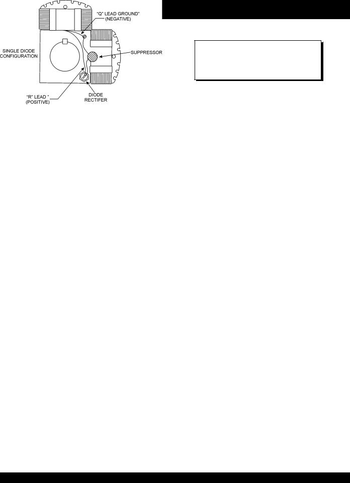
2.Connect the (+) lead of a 12 volt battery to the "R" connection (Figure 16).
Figure 16. Flashing The Rotor Configuration
3.Connect the (-) lead of the battery to the rotor shaft.
4.Re-connect all incoming power leads to the generator
5.Start the generator as outlined in the "Operating Section" of this manual.
6.With a voltmeter check the no load voltage at the 120/
240 output connector located on the control box.
7.The no load should be within 10% of the rated load.
8.If residual voltage is normal, the capacitor is defective and should be replaced.
Diode Check
1.Check the diode individually by removing the (+) rotor lead stud connection (Figure 16). The diode is good if the resistance reading is approximately mid -scale on the lowest ohm scale.
2.Check for leakage in the diode by reversing the polarity.
The diode is good if the resistance reading is infinite.
3.A faulty diode will give a resistance value of zero.
PAGE 30 —KD1800/KD6 A.C. GENERATOR— PARTS & OPERATION MANUAL — REV. #1 (06/16/05)
 Loading...