


PARTS AND OPERATION MANUAL
MULTIQUIP
Model GLW-180H
D.C. WELDER
A.C. GENERATOR
© COPYRIGHT 2004, MULTIQUIP INC.
Revision #5 (03/14/05)
MULTIQUIP INC. |
PARTS DEPARTMENT: |
18910 WILMINGTON AVE. |
800-427-1244 |
CARSON, CALIFORNIA 90746 |
FAX: 800-672-7877 |
310-537-3700 |
SERVICE DEPARTMENT/TECHNICAL ASSISTANCE: |
800-421-1244 |
800-478-1244 |
FAX:310-537-3927 |
FAX:310-631-5032 |
E-mail:mq@multiquip.com • www:multiquip.com
Atlanta • Boise • Dallas • Houston • Newark Montreal, Canada • Manchester, UK
Rio De Janiero, Brazil • Guadalajara, Mexico
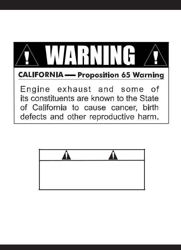
WARNING
CALIFORNIA
Proposition 65 Warning
This product contains or produces chemicals known to the State of California to cause cancer and birth defects
(or other reproductive harm). |
DCL160 |
|
PAGE 2 — GLW-180H A.C. GENERATOR/WELDER — PARTS & OPERATION MANUAL — REV. #5 (03/14/05)

HERE'S HOW TO GET HELP
PLEASE HAVE THE MODEL AND SERIAL NUMBER ON-HAND WHEN CALLING
PARTS DEPARTMENT
800-427-1244 or 310-537-3700 FAX: 800-672-7877 or 310-637-3284
SERVICE DEPARTMENT/TECHNICAL ASSISTANCE
800-478-1244 or 310-537-3700 FAX: 310- 537-4259
WARRANTY DEPARTMENT
888-661-4279, or 310-661-4279 FAX: 310- 537-1173
MAIN
800-421-1244 or 310-537-3700 FAX: 310-537-3927
GLW-180H A.C. GENERATOR/WELDER — PARTS & OPERATION MANUAL — REV. #5 (03/14/05) — PAGE 3

Here's How To Get Help ............................................ |
3 |
Table Of Contents ..................................................... |
4 |
Parts Ordering Procedures ....................................... |
5 |
Rules For Safe Operation ......................................... |
6 |
Operation and Safety Decals .................................... |
7 |
Specifications ............................................................ |
8 |
General Information .................................................. |
9 |
Multiquip GLW-180H — AC
Generator And Welder
Controls and Indicators ........................................... |
10 |
Instrumentation ....................................................... |
11 |
Installation .......................................................... |
12-13 |
Pre-Setup ........................................................... |
14-15 |
Load Application ..................................................... |
16 |
Operating Instructions (Generator) ........................ |
17 |
Operating Instructions (Welder)......................... |
18-19 |
Maintenance ........................................................... |
20 |
Preparation For Long Term Storage ....................... |
21 |
Wiring Diagram ....................................................... |
22 |
Troubleshooting (Engine) ................................... |
23-24 |
Troubleshooting (Generator/Welder) ................. |
25-26 |
Explanation Of Codes In Remarks Column ............ |
28 |
Suggested Spare Parts ........................................... |
29 |
Generator Assembly .......................................... |
30-31 |
Control Box Assembly ........................................ |
32-33 |
Control Box Assembly ........................................ |
34-35 |
Pipe Frame Assembly ........................................ |
36-37 |
Muffler Assembly ............................................... |
38-39 |
Nameplate and Decals....................................... |
40-41 |
TABLE OF CONTENTS
Honda GX340K1 Engine
Cylinder Head Assembly .................................... |
42-43 |
Recoil Starter Assembly..................................... |
44-45 |
Fan Cover Assembly .......................................... |
46-47 |
Camshaft/Valves Assembly ................................ |
48-49 |
Piston/Rings Assembly....................................... |
50-51 |
Air Cleaner Assembly......................................... |
52-53 |
Cylinder Barrel (Recoil) Assembly ..................... |
54-55 |
Cylinder Barrel (Electric) Assembly ................... |
56-57 |
Crankcase Cover/Governor Assembly .............. |
58-59 |
Flywheel/Fan Assembly ..................................... |
60-61 |
Coil Assembly..................................................... |
62-63 |
Crankshaft Assembly ......................................... |
64-65 |
Electric Start Assembly ...................................... |
66-67 |
Governor Controls Assembly ............................. |
68-69 |
Carburetor Assembly ......................................... |
70-71 |
Solenoid Assembly............................................. |
72-73 |
Fuel Cock Assembly .......................................... |
74-75 |
Terms and Conditions Of Sale — Parts .................. |
76 |
NOTE
Specification and part number are subject to change without notice.
PAGE 4 — GLW-180H A.C. GENERATOR/WELDER — PARTS & OPERATION MANUAL — REV. #5 (03/14/05)

PARTS ORDERING PROCEDURES
■Dealer account number
■Dealer name and address
■Shipping address (if different than billing address)
■Return fax number
■Applicable model number
■Quantity, part number and description of each part
■Specify preferred method of shipment:
•UPS Ground
•UPS Second Day or Third Day*
•UPS Next Day*
•Federal Express Priority One (please provide us with your Federal Express account number)*
•Airborne Express*
•Truck or parcel post
*Normally shipped the same day the order is received, if prior to 2PM west coast time.
Earn Extra Discounts when you order by FAX!
All parts orders which include complete part numbers and are received by fax qualify for the following extra discounts:
Number of |
|
line items ordered |
Additional Discount |
1-9 items |
3% |
10+ items** |
5% |
Get special freight allowances when you order 10 or more line items via FAX!**
■UPS Ground Service at no charge for freight
■PS Third Day Service at one-half of actual freight cost
No other allowances on freight shipped by any other carrier.
**Common nuts, bolts and washers (all items under $1.00 list price) do not count towards the 10+ line items.
*DISCOUNTS ARE SUBJECT TO CHANGE*
Fax order discount and UPS special programs revised June 1, 1995
Extra |
Fax |
Discount |
||||
|
|
USA |
||||
|
|
|
||||
for |
Domestic |
|
||||
Dealers |
Only |
|||||
|
||||||
|
|
|
||||
Now! Direct TOLL-FREE access to our Parts Department!
Toll-free nationwide:
800-421-1244 Toll-free FAX:
800/6-PARTS-7 • 800-672-7877
GLW-180H A.C. GENERATOR/WELDER — PARTS & OPERATION MANUAL — REV. #5 (03/14/05) — PAGE 5

CAUTION:
Failure to follow instructions in this manual may lead to serious injury or even death! This equipment is to be operated by trained and qualified personnel only! This equipment is for industrial use only.
The following safety guidelines should always be used when operating the GLW-180H Generator/Welder:
GENERAL SAFETY
■DO NOT operate or service this equipment before reading this entire manual.
■This equipment should not be operated by persons under 18 years of age.
■NEVER operate this equipment without proper protective clothing, shatterproof glasses, steel-toed boots and other protective devices required by the job.
■This generator is a source of potentially LETHAL high voltage. Never permit unqualified personnel-especially children to operate the generator.
■Always refuel in a well-ventilated area, away from sparks and open flames.
■Always use extreme caution when working with flammable liquids. When refueling, stop the engine and allow it to cool. DO NOT smoke around or near the machine. Fire or explosion could result from fuel vapors, or if fuel is spilled on a hot engine.
■This generator is equipped with a ground terminal for your protection. Always complete the grounding path from the generator to an external grounding source.
■NEVER operate this generator, or handle any electrical equipment while standing in water, while bare foot, while hands are wet, or in the rain. Electrical shock could occur causing severe bodily harm or even death.
■Keep electrical cords in good condition. Worn, bare or frayed wiring can cause electrical shock, leading to bodily harm or even death.
■This generator requires an adequate free flow of cooling air. Never operate the generator in any enclosed or narrow area where free flow of the air is restricted. If the air flow is restricted it will cause serious damage to the generator and may cause injury to people.
■NEVER touch the hot exhaust manifold, muffler or cylinder. Allow these parts to cool before servicing generator.
RULES FOR SAFE OPERATION
■Provide adequate ventilation when operating the generator. DO NOT operate the generator in any enclosed or narrow space.The generator's GLWsoline engine gives off DEADLY carbon monoxide GLWs.
■NEVER operate the generator in an explosive atmosphere or near combustible materials. An explosion or fire could result causing severe bodily harm or even death.
■Always make sure that the generator is secure on level ground so that it cannot slide or shift around, endangering workers. Also keep the immediate area free of bystanders.
■When using a concrete vibrator or a similar device that is immersed in a water based solution, make sure the device is equipped with short circuit protection.
■Always use rubber boots and gloves when operating a concrete vibrator or similar device.
■Use adequate size connecting cable for extension.
■Maintain electrical cords in good condition and frequently replace the entire cable of the concrete vibrator with a new one.
■HighTemperatures – Allow the machine and engine to cool before adding fuel or performing service and maintenance functions. Contact with hot components can cause serious burns.
Emergencies
■Always know the location of the nearest fire extinguisher and first aid kit. Know the location of the nearest telephone. Also know the phone numbers of the nearest ambulance, doctor and fire department. This information will be invaluable in the case of an emergency.
Maintenance Safety
■NEVER lubricate components or attempt service on a running machine.
■Always allow the machine a proper amount of time to cool before servicing.
■Keep the machinery in proper running condition.
■Fix damage to the machine immediately and always replace broken parts.
■Dispose of hazardous waste properly.Examples of potentially hazardous waste are used motor oil, fuel and fuel filters.
■DO NOT use food or plastic containers to dispose of hazardous waste.
■DO NOT pour waste, oil or fuel directly onto the ground, down a drain or into any water source
PAGE 6 — GLW-180H A.C. GENERATOR/WELDER — PARTS & OPERATION MANUAL — REV. #5 (03/14/05)
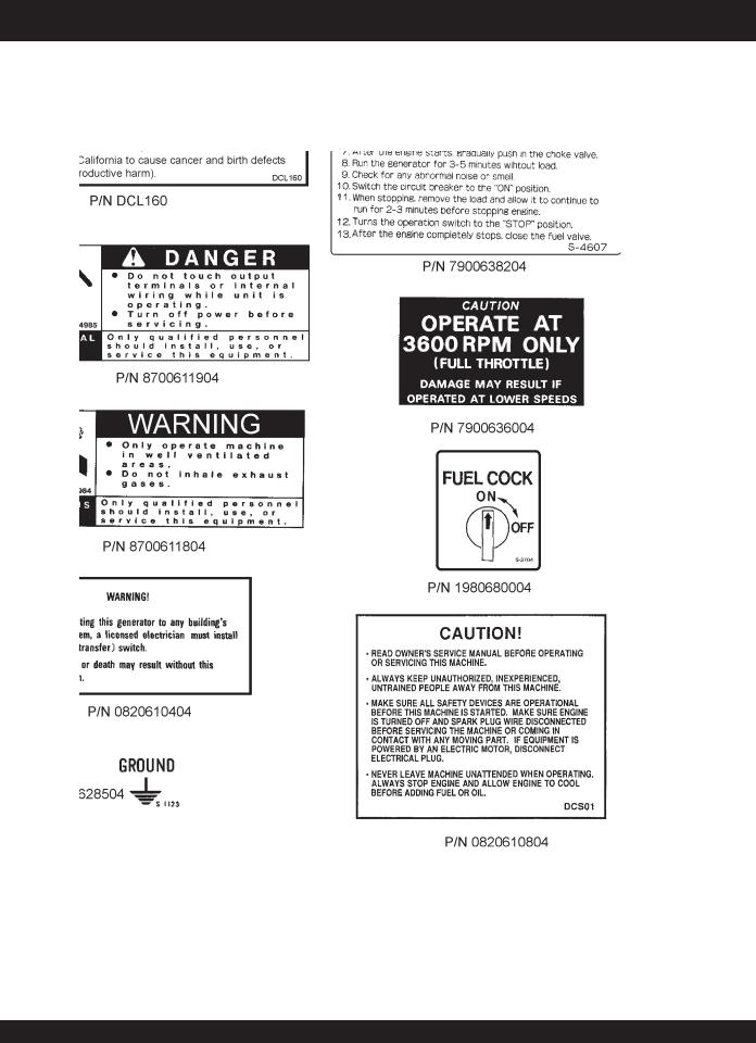
OPERATION AND SAFETY DECALS
Machine Safety Decals
The GLW-180H portable generator is equipped with a number of safety decals.These decals are provided for operator safety and maintenance information.The illustration below shows these decals as they appear on the machine. Should any of these decals become unreadable, replacements can be obtained from your dealer.
GLW-180H A.C. GENERATOR/WELDER — PARTS & OPERATION MANUAL — REV. #5 (03/14/05) — PAGE 7

|
|
|
GLW-180H — SPECIFICATIONS |
|
|
|
|
|
|
|
|
|
|
|
|
|
Table 1. Specifications GLW-180H |
|
|
|
|
|
|
|
|
|
Max. Current |
180 Amps |
|
|
|
|
|
|
|
|
Rated Voltage |
26.4 Volts |
|
|
|
|
|
|
|
Welder |
Duty Cycle |
50% |
|
|
|
|
|
|
|
Adjustable Current Range |
50-180 Amps |
|
|
|
|
|
||
|
|
|
|
|
|
|
Rated Current |
160 Amps |
|
|
|
|
|
|
|
|
Applicable Electrode Size |
5/64" - 5/32" |
|
|
|
|
|
|
|
|
Type Alternator |
2-pole, Brushless Type Revolving Field |
|
|
|
|
|
|
|
|
Max. Output |
4500 Watts |
|
|
|
|
|
|
|
|
Rated Output (continuous) |
4000 Watts |
|
|
|
|
|
|
|
60 Cycle Generator |
Rated Voltage |
120 VAC |
|
|
|
|
|
|
|
Rated Current |
33.3 Amps |
|
|
|
|
|
||
|
|
|
|
|
|
|
Phase |
Single Phase (3-wire) |
|
|
|
|
|
|
|
|
Frequency |
60 Hz |
|
|
|
|
|
|
|
|
Rated Speed |
3600 RPM |
|
|
|
|
|
|
|
|
Power Factor |
100% |
|
|
|
|
|
|
|
|
Model |
Honda GX340K1VD |
|
|
|
|
|
|
|
|
Type |
Air-cooled 4 stroke OVH 25° inclinded cylinder |
|
|
|
|
|
|
|
|
Bore X Stroke |
3.23 in. X 2.52 in. |
|
|
|
(82 mm X 64 mm) |
|
|
|
|
|
|
|
|
|
|
|
|
|
|
Displacement |
20.63 cc |
|
|
|
|
|
|
|
Engine |
Max Output |
8.0 H.P./3600 R.P.M. |
|
|
|
|
|
|
|
|
Fuel Tank Capacity |
Approx. 3-3/4 U.S. Gallons |
|
|
|
|
|
|
|
|
Fuel |
Unleaded Automobile Gasoline |
|
|
|
|
|
|
|
|
Lube Oil Capacity |
1-3/4 pints |
|
|
|
|
|
|
|
|
Speed Control Method |
Centrifugal Fly-weight Type |
|
|
|
|
|
|
|
|
Starting Method |
Recoil Start |
|
|
|
|
|
|
|
Dimension (LXWXH) |
|
31.5 x 22 x 22 in. |
|
|
|
(800 x 560 x 560 mm.) |
|
|
|
|
|
|
|
|
|
|
|
|
|
Dry Net Weight |
|
297 lbs. (135 Kg.) |
|
|
|
|
|
|
Effects of Altitude and Heat
The maximum output of the engine listed above is applicable to supplying electrical power for continuous service at ambient conditions in accordance with SAE Test cord J607. The above ambient conditions are at standard sea level, with a barometric reading of 29.92 inches and a temperature of 60 degrees fahrenheit.
Generally, the engine output power will decrease 3-1/2% for each 1000 feet of altitude above sea level, and 1% for each 10° F fahrenheit above the standard temperature of 60° F .
PAGE 8 — GLW-180H A.C. GENERATOR/WELDER — PARTS & OPERATION MANUAL — REV. #5 (03/14/05)

GLW-180H — GENERAL INFORMATION
WARNING: |
Excitation System |
Before connecting this generator to any building’s electrical system, a licensed electrician must install an isolation (transfer) switch.
Serious injury or death may result without this transfer switch.
GLW-180H FAMILIARIZATION
Generator/Welder
The Multiquip Model GLW-180H generator has been designed as a portable lightweight power source for 60 Hz (singlephase) vibrators, lighting facilities, power tools, submersible pumps and other industrial and construction machinery.
This generator is powered by a HONDA GLWsoline engine.
The alternator, a brushless revolving-field type, is permanently aligned to the engine through rigid coupling.
The generator is mounted on rubber vibration isolators that have a steel base backplate which is attached to the protective steel pipe carrying frame.The protective carrying frame is made of steel tubing and fully wraps around the generator to protect aGLWinst damage.
This portable generator is supplied with a electrical control box. To reduce vibration caused by the engine, the control box is also placed on rubber isolators.
Control Box
The control box has the following: (all outputs are 60 Hz, single phase)
zOne 120V output receptacle.
zOne 120V output receptacle (GFCI protected).
zOne main 40 amp circuit breaker.
zAC Voltmeter
zIdle Control Switch
zOperation Switch
zOutput Terminals (Welding)
All GLW-series generators use a magnet attached to a flywheel to produce AC voltage from a lamp coil beneath the flywheel. As the magnet passes the coil it produces approximately 19-22 AC volts.
This voltage (19-22 VAC) is then sent to the control box that contains three rectifying diodes:
zExcitation (diode 1)
zBattery (diode 2)
zSlow Down (diode 3)
The AC voltage will pass through the excitation diode that converts the voltage to DC power.
This DC power is then sent to the excitation windings housed within the main windings commonly called the "stator".
This voltage is then transferred into the rotor through induction.The rotor contains two diodes within it which rectify the DC voltage and send it out through the main windings, as AC voltage.
Engine
The four-cycle air-cooled HONDA GLWsoline engine is designed to meet every performance requirement of this generator. Reference Table 1, page 8 for engine specifications.
Figure 1 (page 10) shows the basic controls and indicators for the GLW-180H generator.
Idle Control Switch
DO NOT use the idle control switch in conjunction with AC electro-magnetic switches relays etc. Using the idle control switch with these devices will cause the idle control device not to actuate. If any of these devices are being used, leave the idle control switch in the OFF position.
When running capacitor start motors such as submersible pumps, the idle control switch should NOT BE USED. Disconnect the pump or tool from the power source by switching OFF the main circuit breaker.
NOTE
In keeping with Multiquip's policy of constantly improving its products, the specifications quoted herein are subject to change without prior notice.
GLW-180H A.C. GENERATOR/WELDER — PARTS & OPERATION MANUAL — REV. #5 (03/14/05) — PAGE 9

GLW-180H — CONTROLS AND INDICATORS
Figure 1. Controls and Indicators
PAGE 10 — GLW-180H A.C. GENERATOR/WELDER — PARTS & OPERATION MANUAL — REV. #5 (03/14/05)
CAUTION :
When using a combination of dual receptacles, total load should not exceed the rated capacity of the generating.
The definitions below describe the controls and functions of the of the GLW-180 H Generator/Welder.
1.Ground Terminal Equipment – If required ground equipment (power tools etc,) to this ground terminal.This ground is not EARTH ground.
2.120 VAC Twist Lock Receptacle – This unit is supplied with one Twist Lock NEMA L5-30R (120V, 30 Amp) output receptacle.
3.120 VAC GFCI Receptacle – This unit is supplied with one Duplex NEMA (GFCI) 5-20R (120V, 20 Amp) output receptacle.
4.ACVoltmeter – This voltmeter indicates (with a mark) the rated 60 Hz, 120 VAC single phase output voltage. In addition the voltmeter can also be used as a diagnostic tool.
If the voltmeter indicator (needle) is below the rated voltage, engine problems may exist (low/high RPM's).To prevent damage to the generator or power tools turn the generator OFF and consult your authorized Multiquip service dealer.
5.Circuit Breaker – This single-pole, 40 amp breaker is provided to protect both 120 VAC output receptacles from overload.
6.Operation Switch – Must be in the up position (ON) for normal operation.To turn-off generator place this switch in the down position (OFF).
GLW-180H — INSTRUMENTATION
7.Current Regulator – Use this dial to adjust the welder's output to the desired setting.
8.Idle Control Switch – This unit is provided with an automatic idle control for noise suppression and reduced fuel consumption.The automatic idle control automatically enGLWges under a no-load condition.
With the automatic idle control switched “ON”, the engine revolutions will automatically drop to about 2500 rpm (lowspeed operation) within 3 seconds after the load stops.
When the operation is resumed, the engine speed is automatically increased to about 3600 rpm (high-speed operation) as soon as the load is connected.
9.Current Regulator Selector Switch –Two position switch, left position selects minimum current output (min.-130 amps), right position selects maximum current output (max.-180).
10.DC OutputTerminals – Connect the welder's (+) and (-) welding cables to these terminals.
11.FuelTank – The fuel GLWuge is located on the fuel tank and allows easy monitoring of the fuel level.
12.Chassis Ground – Connect earth ground (ground rod) to this lug. See Figure 3.
CAUTION :
When AC power is required, ALWAYS place the current regulator dial in the AC power using range.
CAUTION :
NEVER turn the load ON or OFF by |
|
|
connecting and disconnecting the load |
|
|
power cord from the generator's AC output |
Figure 2. Current Regulator Switch |
|
receptacle. ALWAYS turn the circuit |
||
AC Power Range |
||
breaker OFF to remove power from the |
||
|
||
120 AC recepracles (load). |
|
GLW-180H A.C. GENERATOR/WELDER — PARTS & OPERATION MANUAL — REV. #5 (03/14/05) — PAGE 11
Outdoor Installation
GLW-180H — INSTALLATION
CAUTION :
Install the generator in a location where it will not be exposed to rain or sunshine. Make sure that the generator is on secure level ground so that it cannot slide or shift around. Also install the generator in a manner so that the exhaust will not be discharged in the direction of nearby homes.
The installation site must be relatively free from moisture and dust. All electrical equipment should be protected from excessive moisture.Failure to do will result in deterioration of the insulation and will result in short circuits and grounding.
Foreign materials such as dust, sand, lint and abrasive materials have a tendency to cause excessive wear, not only to the engine parts, but also to the alternator parts.
CAUTION :
Pay close attention to ventilation when operating the generator inside confined areas. The engine exhaust contains noxious elements.
Indoor Installation
Exhaust GLWses from GLWsoline engines are extremely poisonous. Whenever an engine is installed indoors the exhaust fumes must be vented to the outside. The engine should be installed at least two feet from any outside wall.
Using an exhaust pipe which is too long or too small can cause excessive back pressure which will cause the engine to heat excessively and possibly burn the valves
Eliminate the danger of deadly carbon monoxide GLWs. Remember that exhaust fumes from any GLWsoline engine are very poisonous if discharged in a closed room, but harmless if allowed to mix with the outside air.If the generator is installed indoors, you must make provisions for venting the engine exhaust to the outside of the building.
An electric shock is apt to happen when vibrators are used. Pay close attention to handling when operating vibrators and always use rubber boots and gloves to insulate the body from a short circuit.
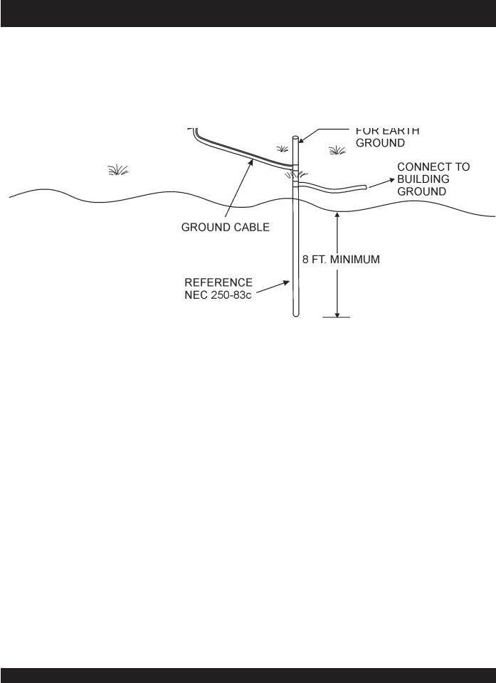
Generator Grounding
To guard aGLWnist electrical shock and possible damage to the equipment, it is important to provide a good EARTH ground.
Article 250 (Grounding) of the National Electrical Code (NEC) provides guide lines for proper grounding and specifies that the cable ground shall be connected to the grounding system of the building (Figure 3) as close to the point of cable entry as practical.
NEC articles 250-91a and 250-95 set the following grounding requirements:
1.Use one of the following wire types to connect the generator to earth ground.
a.Copper - 10 AWG (5.3 mm2) or larger.
b.Aluminum - 8 AWG (8.4 mm2) or larger.
2.When grounding the generator (Figure 3) connect the ground cable between the lock washer and the nut on the generator and tighten the nut fully.Connect the other end of the ground cable to earth ground.
3.NEC article 250-83c specifies that the earth ground rod should be buried a minimum of 8 ft. into the ground.
NOTE
When connecting the generator to any buildings electrical system ALWAYS consult with a licensed electrician.
PAGE 12 — GLW-180H A.C. GENERATOR/WELDER — PARTS & OPERATION MANUAL — REV. #5 (03/14/05)
GLW-180H — INSTALLATION
Grounding
Figure 3. Generator Ground Rod Application
GLW-180H A.C. GENERATOR/WELDER — PARTS & OPERATION MANUAL — REV. #5 (03/14/05) — PAGE 13

GLW-180H — PRE-SETUP
General Inspection Prior to Operation |
Circuit Breaker |
This generator has been thoroughly inspected and accepted prior to shipment from the factory.However, be sure to check for damaged parts or components, or loose nuts and bolts, which could have occurred in transit.
To protect the generator from an overload, a single-pole 40 amp circuit breaker is provided on the control box. Make sure to switch this circuit breaker to the "OFF" position prior to starting the engine.
Ground
The nut and ground terminal on the generator should always be used to connect the generator to a suitable ground. The ground path should be of #8 size wire.
Connect the terminal of the ground wire between the lock washer and the nut at the base of the generator and tighten the nut fully. Connect the other end of the ground wire to a grounding rod as shown in Figure 3.
Extension Cable
When electric power is to be provided to various tools or loads at some distance from the generator, extension cords are normally used. Cables should be sized to allow for distance in length and amperage so that the voltage drop between the generator and point of use (load) is held to a minimum. Use the cable selection chart (Table 2 ) as a guide for selecting the proper extension cable size.
Table 2. Extension Cable Selection (60 Hz, Single Phase Operation)
|
Load In |
|
Maximum Allowable Cable Length |
|
||||
Current in |
Watts |
|
|
|||||
|
|
|
|
|
|
|
||
|
|
|
|
|
|
|
|
|
Amperes |
At 120 |
#10 Wire |
|
#12 Wire |
|
#14 Wire |
|
#16 Wire |
|
|
|
|
|||||
|
Volts |
|
|
|
||||
|
|
|
|
|
|
|
|
|
|
|
|
|
|
|
|
|
|
2.5 |
300 |
1000 ft. |
|
600 ft. |
|
375 ft. |
|
250 ft. |
|
|
|
|
|
|
|
|
|
5 |
600 |
500 ft. |
|
300 ft. |
|
200 ft. |
|
125 ft. |
|
|
|
|
|
|
|
|
|
7.5 |
900 |
350 ft. |
|
200 ft. |
|
125 ft. |
|
100 ft. |
|
|
|
|
|
|
|
|
|
10 |
1200 |
250 ft. |
|
150 ft. |
|
100 ft. |
|
|
|
|
|
|
|
|
|
|
|
15 |
1800 |
150 ft. |
|
100 ft. |
|
65 ft. |
|
|
|
|
|
|
|
|
|
|
|
20 |
2400 |
125 ft. |
|
75 ft. |
|
50 ft. |
|
|
|
|
|
|
|
|
|
|
|
CAUTION: Equipment damage can result from low voltage. |
|
|
|
|||||
|
|
|
|
|
|
|
|
|
PAGE 14 — GLW-180H A.C. GENERATOR/WELDER — PARTS & OPERATION MANUAL — REV. #5 (03/14/05)
Lubrication Oil
Fill the engine crankcase with lubricating oil through the filler hole, but do not overfill. Make sure the generator is level.
With the dipstick inserted all the way, but without being screw into the filler hole, verify that the oil level is maintained between the two notches on the dipstick.
The oil listed in Table 3 is recommended to ensure better engine performance. Use class SC or higher grade motor oil.
Table 3. Recommended Motor Oil
Temperature Range |
Type Oil |
104° F ~ 23° F
SAE 30
(40° C ~ -5°C)
23° F ~ 5° F
SAE 20 or sae 10W-30
(-5° C ~ -15°C)
Below 5° C (-15°) |
SAE 10W or SAE 10W-30 |
GLW-180H — PRE-SETUP
Fuel
Close the fuel cock before filling the tank. Fill the fuel tank with clean and fresh unleaded GLWsoline. DO NOT fill the tank beyond capacity.
Pay attention to the fuel tank capacity when replenishing fuel. Refer to the fuel tank capacity listed on page 8 Specification Table 1.
The fuel tank cap must be closed tightly after filling.
Handle fuel in a safety container. If the container does not have a spout, use a funnel.
CAUTION :
Never fill the fuel tank while the engine is running or in the dark. GLWsoline spillage on a hot engine can cause a fire or explosion. If GLWsoline spillage occurs, wipe up the spilled GLWsoline completely to prevent fire hazards.
GLW-180H A.C. GENERATOR/WELDER — PARTS & OPERATION MANUAL — REV. #5 (03/14/05) — PAGE 15

Single Phase Load
Always be sure to check the nameplate on the generator and equipment to insure the wattage, amperage and frequency requirements are satisfactorily supplied by the generator for operating the equipment.
Generally, the wattage listed on the nameplate of the equipment is its rated output. Equipment may require 130—
150% more wattage than the rating on the nameplate, as the wattage is influenced by the efficiency, power factor and starting system of the equipment.
NOTE
If wattage is not given on the equipment's name plate, approximate wattage may be determined by multiplying nameplate voltage by the nameplate amperage.
WATTS = VOLTAGE x AMPERAGE
To determine the running wattage for your load, multiply the running wattage as indicated by steps 1, 2, and 3 below:
1.INCANDESCENT LOADS
Lights, heaters and similar appliances.
Total the running wattage and multiply by 1.
Example:
29 light bulbs @ 100W each = 2.9 KW use a 3 KW generator.
2.SMALL MOTORS
Drills and other small power tools.
Total the running wattage and multiply by 2.
Example:
A 1 inch drill runs at 1 KW use a 2 KW generator.
3.LARGE MOTORS
Submersible pumps, table saws etc.
Total the running wattage and multiply by 3.
Example:
A conveyor belt runs at 8 KW use a 24 KW generator.
GLW-180H — LOAD APPLICATION
CAUTION:
Motors and motor-driven equipment draw much greater current for starting than during operation.
An inadequate size connecting cable which cannot carry the required load can cause a voltage drop which can burn out the appliance or tool and overheat the cable.
The idle control is operated at minimum load capacity of 100W. If the load capacity is less than 100W, throw the idle control switch to the OFF position.
PAGE 16 — GLW-180H A.C. GENERATOR/WELDER — PARTS & OPERATION MANUAL — REV. #5 (03/14/05)

GLW-180H — GENERATOR OPERATING INSTRUCTIONS
Before Starting
1.Be sure to disconnect the electrical load and switch the main circuit breaker to the “OFF” position prior to starting the engine.
2.Never start the engine with the main circuit breaker “ON”.
3.Check the lubricating oil level prior to starting the engine.
Make sure the generator is level. The oil level must be maintained between two notches on the dipstick.
4.When there is not enough lubricating oil, fill the crankcase with high grade motor oil. Use a high quality detergent oil classified SC, SD or SE. (See Table 3 on page 15)
CAUTION:
|
z NEVER start the engine when the oil level |
|
is below the lower mark on the dipstick. |
|
z Check the fuel level on the fuel GLWuge. |
|
When fuel is low, fill the fuel tank with |
|
clean fresh unleaded automotive |
|
GLWsoline. |
Starting |
z If GLWsoline spillage occurs, completely |
wipe up the spilled GLWsoline. |
1.Place the idle control switch in the “ON” (up) position.
2.Close the choke. Adjust the opening of the choke valve according to operating conditions. When the engine is warm or the air temperature is high, close the choke valve halfway or open it all the way.
3.Confirm that the main circuit breaker on the generator control box is “OFF”.
4.Set the operation switch to the “ON” position and grasp the starting rope and slowly pull it out. The resistance becomes hardest at a certain position, corresponding to the compression point. Rewind the rope a little from that point and pull out sharply.
5.If the engine fails to start, repeat the procedure.
CAUTION:
zDO NOT pull the starter rope all the way to the end.
zDO NOT release the starter rope after pulling. Allow it to rewind as soon as possible.
Warm up
1.When the engine starts, open the choke slowly.
2.Run the engine at low speed for 3 minutes without load until the engine warms up.
3.Turn the idle control switch to the "OFF" (down) position and check the voltage by referring to the voltmeter on the control box.
CAUTION:
DO NOT change the engine speed control lever which has been set at the factory prior to shipping.
1.Check the generator for abnormal noise and smells.Then connect the load to the receptacles of the generator.
2.Switch the main circuit breaker to the “ON” position and turn the idle control switch to the “ON” (down) position for normal (load) engine operation.
Operation
Check the voltage by referring to the voltmeter on the control box. When the voltmeter indicates 120 volts, 120 volts from the 120V receptacles and 240 volts from the 240V receptacle can be obtained at the same time. Refer to Figure 1, Controls and Indicators, item 4 on page 10.
Stopping the Engine
CAUTION:
NEVER stop the engine suddenly while running at high speeds.
1.Remove the load from the generator. Place the circuit breaker in the “OFF” position. Refer to Figure 1, item 5 on page 10. Run the engine (no-load) with the idle control switch set to the ON position for three to five minutes, then stop the engine.
2.Turn the START/STOP switch to the “STOP” position.
3.Never stop the engine suddenly while running at high speed.
4.Close the fuel cock.
GLW-180H A.C. GENERATOR/WELDER — PARTS & OPERATION MANUAL — REV. #5 (03/14/05) — PAGE 17
GLW-180H —WELDER OPERATING INSTRUCTIONS
Welding Cables and Polarities
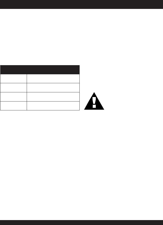
Connect the welding cables (Figure 4) to the welder's output terminals located on the control panel. The output terminals have (+) and (-) polarities. Select the appropriate polarities according to the application (SeeWelding Application,Table 5).
NOTE
Attach terminal connectors at the end of each cable. NEVER connect exposed wires (Figure 5) directly to the terminal. Exposed wiring may cause shocks or di-electric breakdown from poor contact.
Figure 4. Welding Cable Connection
(Correct)
|
|
Figure 5. Welding Cable Connection |
|
|
|
|
(Incorrect) |
|
|
|
|
|
Table 4. Welding Applications |
||
|
|
|
|
POLARITY |
WELDING METHOD |
|
TYPICAL APPLICATIONS |
|
|
|
|
|
(+) ... Grounding (Base Metal) |
|
Welding steel materials for general |
Straight Polarity |
|
structures, and thickness plates. |
|
|
|
||
|
|
|
|
|
(-) ... Welder Holder |
|
Arc welding for copper alloy |
|
|
|
|
|
(+) ... Welder Holder |
|
Build-up welding, ARC welding of |
Reverse Polarity |
|
thin plates |
|
|
|
||
|
|
|
|
|
(+) ... Grounding (Base Metal) |
|
Arc welding of stainless steel |
|
|
|
|
Note: Reguarding the selection of the polarity in the CV charactertics, follow the instructions from the wire maker.
PAGE 18 — GLW-180H A.C. GENERATOR/WELDER — PARTS & OPERATION MANUAL — REV. #5 (03/14/05)
GLW-180H —WELDER OPERATING INSTRUCTIONS
Welding Cables
The required cable welding size is governed by this simple rule:The longer the welding cable, or the greater the welding current, the thicker (copper strands) the calbe must be.
Select a welding cable with adequate thickness according to the cable length and welding amperage (current) as listed in Table 5.
Table 5. Welder Cable Sizes
Welder Output |
Cable Length |
Cable Size |
|
Current |
|||
|
|
||
|
|
|
|
|
50 |
No. 3 |
|
|
|
|
|
|
100 |
No. 3 |
|
|
|
|
|
|
125 |
No. 3 |
|
100 |
|
|
|
150 |
No. 3 |
||
|
|
|
|
|
200 |
No. 3 |
|
|
|
|
|
|
250 |
No. 3 |
|
|
|
|
|
|
300 |
No. 3 |
|
|
|
|
|
|
50 |
No. 3 |
|
|
|
|
|
|
100 |
No. 3 |
|
|
|
|
|
|
125 |
No. 3 |
|
150 |
|
|
|
150 |
No. 3 |
||
|
|
|
|
|
200 |
No. 2 |
|
|
|
|
|
|
250 |
No. 1 |
|
|
|
|
|
|
300 |
No. 1 |
|
|
|
|
|
|
50 |
No. 3 |
|
|
|
|
|
|
100 |
No. 3 |
|
|
|
|
|
|
125 |
No. 3 |
|
|
|
|
|
200 |
150 |
No. 2 |
|
|
|
|
|
|
200 |
No. 1 |
|
|
|
|
|
|
250 |
No. 1/0 |
|
|
|
|
|
|
300 |
No. 1/0 |
|
|
|
|
Duty Cycle
The duty cycle for the generator/welder is based on 10 minute intervals. See Table 6 below.
Table 6. Duty Cycle
Welding |
110 or |
125 |
145 |
160 |
180 |
|
Current |
Less |
|||||
|
|
|
|
|||
|
|
|
|
|
|
|
Duty |
100 |
80 |
60 |
50 |
40 |
|
Cycle% |
||||||
|
|
|
|
|
||
|
|
|
|
|
|
CAUTION:
NEVER switch the current range selector switch during any welding operation.
1.Connect the welding cables (electrodes) to the generator's output terminals (Figure 4). For minimum welding current (min-130 amps), use an eyelet terminal connector with a 5/64" to 1/8" diameter, for maximum welding current (110 - max amps), use an eyelet terminal connector with a 3/32" to 5/32" diameter
2.Set the current regulator control switch on the control panel (Figure X) to the desired setting. The inner scale is for low current, the outer scale is high current output.
CAUTION: |
Figure 6. Current Regulator/Range Switches |
To prevent serious accidents, ALWAYS turn off the generator/welder ( operation switch) and set the main circuit breaker to the OFF position.
3.Set the current range control switch (Figure 7) to either low or high. DO NOT change the position of this switch while welding.
GLW-180H A.C. GENERATOR/WELDER — PARTS & OPERATION MANUAL — REV. #5 (03/14/05) — PAGE 19
General Inspection
At least daily or prior to each use, the generating set should be cleaned and inspected for deficiencies. Check for loose, missing or damaged nuts, bolts or other fasteners. Also check for fuel or oil leaks.
Engine Side (Refer to the Engine Instruction Manual)
Check Oil Level
Check the crankcase oil level prior to each use, or when the fuel tank is filled. Make sure the generating set is level. The oil level must be between the two notches on the dipstick.
Changing Oil
Change oil after the first 20 hours of operation. Drain and refill the engine crankcase every 50 operating hours or once a week thereafter.Drain crankcase oil into a suitable container while engine is still warm. Replace the drain plug tightly. Add oil through the filler hole.
Air Cleaner
Every 50 hours: Remove air cleaner element (std. or heavy duty types), and wash in kerosene or liquid detergent and hot water. Wrap foam element in a cloth and squeeze dry.
Wipe heavy duty paper element dry with toweling. Saturate element with kerosene; squeeze excess from foam element.
Wipe excess from heavy duty paper element.
GLW-180H — MAINTENANCE
Service Daily
If engine is operating in very dusty and dry grass conditions. A clogged air cleaner will result in high fuel consumption, loss of power and excessive carbon buildup in the combustion chamber.
Cleaning the Fuel Strainer
Clean the fuel strainer if it contains dust or water. Remove dust or water in the strainer cap and wash it in GLWsoline. Securely fasten the fuel strainer cap so that fuel will not leak. Check the fuel strainer every 200 hours of operation or once a month.
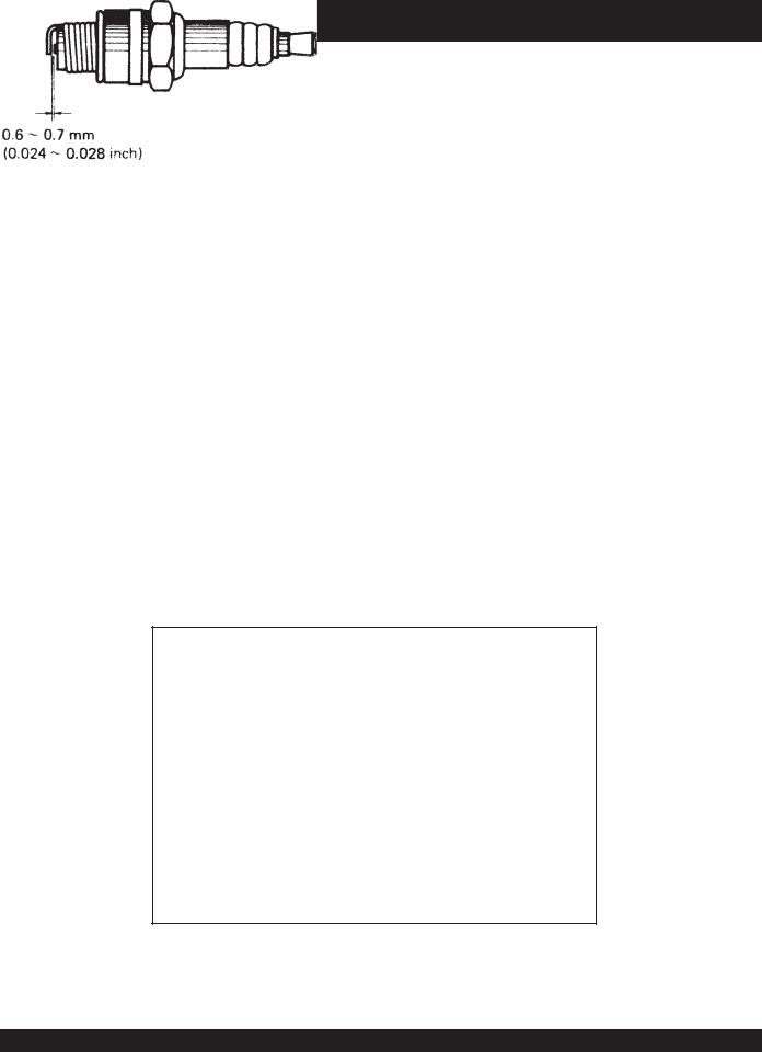
Spark Plug
Remove carbon build-up on the spark plug (Figure 5) with a wire brush. Set the spark plug GLWp to 0.6—0.7mm (0.024-
0.028 inch).Tighten with a spark plug socket wrench. Clean the spark plug every 50 operating hours or once a week.
Figure 5. Spark Plug GLWp
PAGE 20 — GLW-180H A.C. GENERATOR/WELDER — PARTS & OPERATION MANUAL — REV. #5 (03/14/05)
GLW-180H — PREPARATION FOR LONG -TERM STORAGE
Generator Storage
For storage of the generating set for over 30 days, the following is required:
zDrain the fuel tank completely.
zRun the engine until the GLWsoline in the carburetor is completely consumed.
zCompletely drain the oil from the crankcase and refill with fresh oil.
zRemove the spark plug, pour 2 or 3 cc of SAE 30 oil into the cylinder and crank slowly to distribute the oil.
zSlowly rotate the engine a few times with the starter Rope and install a new plug.
zPull out the starter rope slowly and stop at the compression point.
zClean all external parts of the generating set with a cloth.
zCover the generating set and store in a clean, dry place.
GLW-180H A.C. GENERATOR/WELDER — PARTS & OPERATION MANUAL — REV. #5 (03/14/05) — PAGE 21
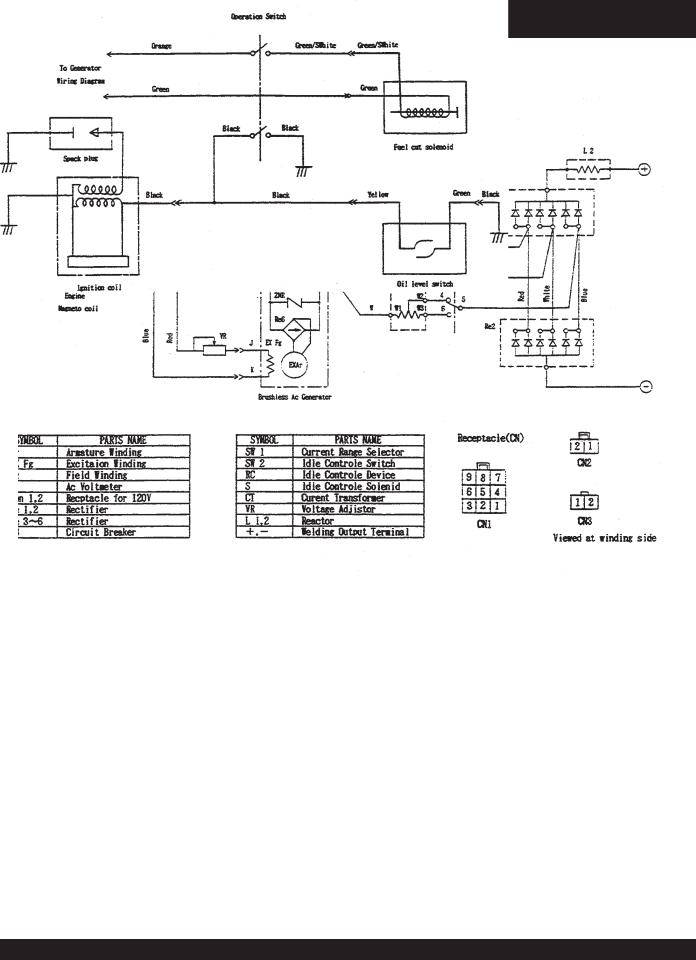
GLW-180H —WIRING DIAGRAM GENERATOR/ ENGINE
GENERATOR
ENGINE
PAGE 22 — GLW-180H A.C. GENERATOR/WELDER — PARTS & OPERATION MANUAL — REV. #5 (03/14/05)

GLW-180H —TROUBLESHOOTING (ENGINE)
Practically all breakdowns can be prevented by proper handling and maintenance inspections, but in the event of a breakdown, please take a remedial action following the
diagnosis based on the Engine Troubleshooting (Table 7) information shown below and on the proceeding page. If the problem cannot be remedied, please leave the unit just as it is and consult our company's business office or service plant.
TABLE 7. ENGINE TROUBLESHOOTING
SYMPTOM |
POSSIBLE PROBLEM |
SOLUTION |
|
|
|
|
|
|
Inspect carburetor to see if fuel |
Check fuel line |
|
|
is reaching it? |
|
|
|
|
|
|
|
No Fuel? |
Add Fuel |
|
|
|
|
|
|
Water in fuel tank? |
Flush or replace fuel tank. |
|
|
|
|
|
|
Fuel filter clogged? |
Replace fuel filter |
|
|
|
|
|
|
Stuck carburetor? |
Check float mechanism. |
|
Poor starting |
|
|
|
Spark plug is red? |
Spark plug is fouled. Check tranistor ignition unit. |
||
|
|
|
|
|
Spark plug is blue-white? |
Insufficient compression, injected air leaking. Carburetor jets are |
|
|
clogged (overflow). |
||
|
|
||
|
|
|
|
|
No spark present at tip of spark |
Tranistor ignition unit broken, high voltage cord cracked or broken. |
|
|
plug? |
Start/Stop switch broken. Replace spark plug if fouled. |
|
|
|
|
|
|
No oil? |
Add oil as required. |
|
|
|
|
|
|
Oil pressure alarm lamp blinks |
Check Automatic shutdown circuit "oil sensor". |
|
|
upon starting? |
||
|
|
||
|
|
|
|
|
Engine will not turn over? |
Replace cylinder and piston and if necessary axel joint. |
|
|
|
|
|
|
Cylinder head connecting bolts |
Tighten cylinder head connecting bolts. |
|
|
loose? |
||
|
|
||
|
|
|
|
Insufficient power output "no |
Cylinder head gasket damaged? |
Replace cylinder head gasket. |
|
compression" |
|
|
|
Malfunction of valve seat? |
Re-seat valves. |
||
|
|||
|
|
|
|
|
Spark plug is loose? |
Replace spark plug. |
|
|
|
|
|
|
Worn piston rings? |
Replace piston rings. |
|
|
|
|
|
|
Malfunction in air-cleaner |
Clean or replace air filter. |
|
|
system, air filter clogged? |
||
|
|
||
|
|
|
|
|
Air leaking in from interface |
Tighten bolts between carburetor and cylinder head. Replace |
|
Insufficient power output |
between carburetor and cylinder |
cylinder head gasket. |
|
"compression" |
head? |
|
|
|
|
|
|
|
|
Clean or replace fuel filter. |
|
|
Malfunction in fuel system? |
Clean or replace carburetor. |
|
|
|
Check carburetor float. |
|
|
|
|
GLW-180H A.C. GENERATOR/WELDER — PARTS & OPERATION MANUAL — REV. #5 (03/14/05) — PAGE 23

GLW-180H —TROUBLESHOOTING (ENGINE)
TABLE 7. ENGINE TROUBLESHOOTING (CONTINUED)
SYMPTOM |
POSSIBLE PROBLEM |
SOLUTION |
|
|
|
|
|
Insufficient power output |
Malfunction in cooling fan? |
Check or replace cooling fan. |
|
|
|
||
"compression" and overheats |
Air in-take filter clogged? |
Clean or replace air in-take filter. |
|
|
|||
|
|
|
|
|
Over accumulation of exhaust |
Clean and check valves. |
|
Burns to much fuel |
products? |
Check muffler, replace if necessary. |
|
|
|
||
|
Wrong spark plug? |
Replace spark plug with manufactures suggested type spark plug. |
|
|
|
|
|
|
Lubricating oil is wrong |
Replace lubricating oil with correct viscosity. |
|
Exhaust color is continiously |
viscosity? |
||
|
|||
"WHITE" |
Worn rings? |
Replace rings |
|
|
|||
|
|
|
|
|
Air cleanner clogged? |
Clean or replace air cleaner. |
|
|
|
|
|
|
Choke valve has not been set |
Adjust choke valve to the correct position. |
|
Exhaust color is continiously |
to the correct position? |
|
|
|
|
||
|
|
||
"BLACK" |
Carburetor defective, seal on |
Replace carburetor or seal. |
|
|
carburetor broken? |
|
|
|
|
|
|
|
Poor carburetor adjustment |
Adjust carburetor. |
|
|
"engine runs too rich? |
|
|
|
|
|
PAGE 24 — GLW-180H A.C. GENERATOR/WELDER — PARTS & OPERATION MANUAL — REV. #5 (03/14/05)
 Loading...