


OPERATION AND PARTS MANUAL
MODEL GA-6H/GA-6HA
Portable Generators
(HONDA GASOLINE ENGINE)
Revision #0 (06/02/05)
THIS MANUAL MUST ACCOMPANY
THE EQUIPMENT AT ALLTIMES.
PAGE 2 — GA-6H/GA-6HA A.C. GENERATORS — OPERATION & PARTS MANUAL — REV. #0 (06/02/05)
HERE'S HOW TO GET HELP
PLEASE HAVE THE MODEL AND SERIAL
NUMBER ON-HAND WHEN CALLING
MULTIQUIP CORPORATE OFFICE |
|
18910 Wilmington Ave. |
800-421-1244 |
Carson, CA 90746 |
FAX:310-537-3927 |
Email: mq@multiquip.com |
|
Internet: www.multiquip.com |
|
PARTS DEPARTMENT |
|
800-427-1244 |
FAX:800-672-7877 |
310-537-3700 |
FAX:310-637-3284 |
MAYCO PARTS |
|
800-306-2926 |
FAX:800-672-7877 |
310-537-3700 |
FAX:310-637-3284 |
SERVICE DEPARTMENT |
|
800-421-1244 |
FAX:310-537-4259 |
310-537-3700 |
|
TECHNICAL ASSISTANCE |
|
800-478-1244 |
FAX:310-631-5032 |
WARRANTYDEPARTMENT |
|
800-421-1244, EXT. 279 |
FAX:310-537-1173 |
310-537-3700, EXT. 279 |
|
© COPYRIGHT 2005, MULTIQUIP INC.
Multiquip Inc, the MQ logo are registered trademarks of Multiquip Inc. and may not be used, reproduced, or altered without written permission. All other trademarks are the property of thier respective owners and used with permission.
This manual MUST accompany the equipment at all times.This manual is considered a permanent part of the equipment and should remain with the unit if resold.
The information and specifications included in this publication were in effect at the time of approval for printing. Illustrations are based on the MQ GA-6H/GA-6HA Portable Generators. Illustrations, descriptions, references and technical data contained in this manual are for guidance only and may not be considered as binding. Multiquip Inc. reserves the right to discontinue or change specifications, design or the information published in this publication at any time without notice and without incurring any obligations.
To find the latest revision of this publication, visit our website at: www.multiquip.com
GA-6H/GA-6HA A.C. GENERATORS — OPERATION & PARTS MANUAL — REV. #0 (06/02/05) — PAGE 3

Multiquip GA-6H/GA-6HA
AC Portable Generators
Here's How To Get Help ............................................ |
3 |
Table Of Contents ..................................................... |
4 |
Parts Ordering Procedures ....................................... |
5 |
Safety Message Alert Symbols .............................. |
6-7 |
Rules for Safe Operation ..................................... |
8-10 |
Operation and Safet Decals.................................... |
11 |
Specifications (Generator) ...................................... |
12 |
Specifications (Engine) ........................................... |
13 |
Dimensions ............................................................. |
14 |
General Information ................................................ |
15 |
Load Application ..................................................... |
16 |
Controls and Indicators ...................................... |
17-19 |
Generators Refueling.............................................. |
20 |
Installation .......................................................... |
21-22 |
Pre-Inspection ......................................................... |
23 |
Pre-Inspection (Engine) .......................................... |
24 |
Initial Start-up (Engine) ........................................... |
25 |
Initial Start-up/Generators Operation ..................... |
26 |
Generators Operation/Shutdown ............................ |
27 |
Preparation For Long Term Storage ....................... |
28 |
Maintenance (Engine)........................................ |
30-31 |
Wiring Diagram (GA-6H Generator) ....................... |
32 |
Wiring Diagram (GA-6HA Generator) ..................... |
33 |
Troubleshooting (Engine) ................................... |
34-35 |
Troubleshooting (Generator) .................................. |
36 |
Explanation of Code In Remarks Column............... |
38 |
Suggested Spare Parts ........................................... |
39 |
TABLE OF CONTENTS
HONDA GX340K1EDN2 ENGINE
Air Cleaner Assembly......................................... |
52-53 |
Camshaft Assembly ........................................... |
54-55 |
Carburetor Assembly ......................................... |
56-57 |
Control Assembly ............................................... |
58-59 |
Crankcase Cover Assembly ............................... |
60-61 |
Crankshaft Assembly ......................................... |
62-63 |
Cylinder Barrel Assembly ................................... |
64-65 |
Cylinder Head Assembly .................................... |
66-67 |
Fan Cover Assembly .......................................... |
68-69 |
Flywheel Assembly ............................................ |
70-71 |
Ignition Coil Assembly ........................................ |
72-73 |
Piston Assembly ................................................. |
74-75 |
Recoil Starter Assembly..................................... |
76-77 |
Solenoid Assembly............................................. |
78-79 |
Label Assembly .................................................. |
80-81 |
Terms and Conditions Of Sale — Parts .................. |
82 |
Specification and part number are subject to change without notice.
Component Drawings
Nameplate and Decals....................................... |
40-41 |
Generators Assembly ........................................ |
42-43 |
Control Box Assembly (GA-6H) ......................... |
44-45 |
Control Box Assembly (GA-6HA) ....................... |
46-47 |
Muffler Assembly .............................................. |
48-49 |
Pipe Frame Assembly ........................................ |
50-51 |
PAGE 4 — GA-6H/GA-6HA A.C. GENERATORS — OPERATION & PARTS MANUAL — REV. #0 (06/02/05)

PARTS ORDERING PROCEDURES
When ordering parts,
please supply the following information:
Dealer account number
Dealer name and address
Shipping address (if different than billing address)Return fax number
Applicable model number
Quantity, part number and description of each part
Specify preferred method of shipment:
FedEx or UPS Ground
FedEx or UPS Second Day or Third Day
FedEx or UPS Next Day
Federal Express Priority One
DHL
Truck
Note:Unless otherwiseindicatedby customer,all orders are treated as “Standard Orders”, and will ship within 24 hours.We will make every effort to ship “Air Shipments” the same day that the order is received, if prior to 2PM west coast time. “Stock Orders” must be so noted on fax or web forms.
Here’s how to get help...
Please have the model and serial number on hand when calling.
MULTIQUIP CORPORATE OFFICE
18910 Wilmington Ave. |
800-421-1244 |
Carson, CA 90746 |
FAX: 310-537-3927 |
Email: mq@multiquip.com |
|
Internet: www.multiquip.com |
|
PARTS DEPARTMENT |
|
800-427-1244 |
FAX: 800-672-7877 |
310-537-3700 |
FAX: 310-637-3284 |
MAYCO PARTS |
|
800-306-2926 |
FAX: 800-672-7877 |
310-537-3700 |
FAX: 310-637-3284 |
SERVICE DEPARTMENT |
|
800-421-1244 |
FAX: 310-537-4259 |
310-537-3700 |
|
TECHNICAL ASSISTANCE |
|
800-478-1244 |
FAX: 310-631-5032 |
WARRANTY DEPARTMENT |
|
800-421-1244, EXT. 279 |
FAX: 310-537-1173 |
310-537-3700, EXT. 279 |
|
Place Your Parts Order Via Web or Fax For Even More Savings!
(Domestic USA Dealers Only)
Extra Discounts!
All parts orders which include complete part numbers and are received by our automated web parts order system, or by fax qualify for the following extra discounts:
Ordered |
Standard |
Stock orders |
|
via |
orders |
($750 list and above) |
|
|
|
|
|
Fax |
3% |
10% |
|
Web |
5% |
10% |
|
Special freight allowances when you order 10 or more line items via Web or Fax!**
FedEx Ground Service at no charge for freight
No other allowances on freight shipped by any other carrier.
**Common nuts, bolts and washers (all items under $1.00 list price) do not count towards the 10+ line items.
NOTE:DISCOUNTSARESUBJECTTOCHANGE
MULTIQUIP INC. |
Direct TOLL-FREE access |
18910 WILMINGTON AVENUE |
|
POST OFFICE BOX 6254 |
to our Parts Department: |
|
|
CARSON, CALIFORNIA 90749 |
|
310-537-3700 • 800-421-1244 |
Toll-free nationwide — 800-427-1244 |
FAX: 310-537-3927 |
Toll-free FAX — 800-6-PARTS-7 (800/672-7877) |
E-MAIL:mq@multiquip.com |
|
INTERNET:www.multiquip.com |
|
GA-6H/GA-6HA A.C. GENERATORS — OPERATION & PARTS MANUAL — REV. #0 (06/02/05) — PAGE 5
GA-6H/GA-6HA — SAFETY MESSAGE ALERT SYMBOLS
FORYOUR SAFETY AND THE SAFETY OF OTHERS!
Safety precautions should be followed at all times when operating this equipment. Failure to read and understand the Safety Messages and Operating Instructions could result in injury to yourself and others.
This Owner's Manual has been developed to provide complete instructions for the safe and efficient operation of the MQ Model GA-6H/ GA-6HA Portable Generators. Refer to the engine manufacturers instructions for data relative to its safe operation.
Before using these generators, ensure that the operating individual has read and understands all instructions in this manual.
HAZARD SYMBOLS
Potential hazards associated with the operation of a GA-6H/ GA-6HA Portable Generators will be referenced with Hazard Symbols which appear throughout this manual, and will be referenced in conjunction with Safety Message Alert
Symbols.
 WARNING Lethal Exhaust Gas Hazards
Engine exhaust gases contain poisonous carbon monoxide. This gas is colorless and odorless, and can cause death if inhaled. NEVER operate this equipment in a confined area or enclosed structure that does not provide ample free flow air.
SAFETY MESSAGE ALERT SYMBOLS
The three (3) Safety Messages shown below will inform you about potential hazards that could injure you or others. The Safety Messages specifically address the level of exposure to the operator, and are preceded by one of three words: DANGER,
 DANGER
You WILL be KILLED or SERIOUSLY INJURED if you DO NOT follow these directions.
 WARNING
You CAN be KILLED or SERIOUSLY INJURED if you DO NOT follow these directions.
 CAUTION
You CAN be INJURED if you DO NOT follow these directions.
 WARNING Explosive Fuel Hazards
Gasoline is extremely flammable, and its vapors can cause an explosion if ignited. DO NOT start the engine near spilled fuel or combustible fluids.
DO NOT fill the fuel tank while the engine is running or hot. DO NOT overfill tank, since spilled fuel could ignite if it comes into contact with hot engine parts or sparks from the ignition system. Store fuel in approved containers, in well-ventilated areas and away from sparks and flames.
|
WARNING |
Burn Hazards |
Engine components can generate extreme heat. To prevent burns, DO NOT touch these areas while the engine is running or immediately after operations. Never operate the engine with heat shields or heat guards removed.
|
WARNING |
Respiratory Hazards |
ALWAYS wear approved respiratory protection when required.
PAGE 6 — GA-6H/GA-6HA A.C. GENERATORS — OPERATION & PARTS MANUAL — REV. #0 (06/02/05)

GA-6H/GA-6HA — SAFETY MESSAGE ALERT SYMBOLS
|
CAUTION |
Rotating Parts Hazards |
|
|
|
NEVER operate equipment with covers, or guards removed. Keep fingers, hands, hair and clothing away from all moving parts to prevent injury.
 CAUTION Accidental Starting Hazards
ALWAYS place the power source, circuit breakers or ON/OFF switch in the OFF position, when the generators is not in use, unless connected to transfer switch.
 CAUTION Eye and Hearing Hazards
ALWAYS wear approved eye and hearing protection.
|
CAUTION |
Equipment Damage |
|
Hazards |
|
|
|
Other important messages are provided throughout this manual to help prevent damage to your portable generator, other property, or the surrounding environment.
GA-6H/GA-6HA A.C. GENERATORS — OPERATION & PARTS MANUAL — REV. #0 (06/02/05) — PAGE 7
GA-6H/GA-6HA — RULES FOR SAFE OPERATION
|
DANGER |
Read this manual! |
|
|
|
Failure to follow instructions in this manual may lead to serious injury or even death! This equipment is to be operated by trained and qualified personnel only!
This equipment is for industrial use only.
The following safety guidelines should always be used when operating the GA-6H/GA-6HA Portable Generator:
GENERAL SAFETY
■DO NOT operate or service this equipment before reading this entire manual.
■This equipment should not be operated by persons under
18 years of age.
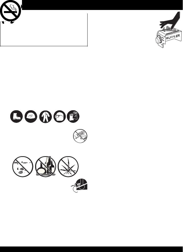
■NEVER operate this equipment without proper protective clothing, shatterproof glasses, steel-toed boots and other protective devices required by the job.
■NEVER operate this equipment when not
feeling well due to fatigue, illness or taking medicine.
■NEVER operate this equipment under the influence of drugs or alcohol.
■ALWAYS wear proper respiratory (mask), 
 hearing and eye protection equipment when
 operating the generator.
■Whenever necessary, replace nameplate, operation and safety decals when they become difficult read.
■Manufacturer does not assume responsibility for any accident due to equipment modifications.
■NEVER use accessories or attachments, which are not recommended by Multiquip for this equipment. Damage to the equipment and/or injury to user may result.
■NEVER touch the hot exhaust manifold, muffler or cylinder. Allow these parts to cool before servicing engine or generators.
■The engine section of this generators requires an adequate free flow of cooling air. NEVER operate the generators in any enclosed or narrow area where free flow of the air is restricted. If the air flow
is restricted it will cause serious damage to the generators or engine and may cause injury to people. Remember the generator's engine gives off DEADLY carbon monoxide gas.
■ALWAYS refuel in a well-ventilated area, away from sparks and open flames.
■ALWAYS use extreme caution when working with flammable liquids. When refueling, stop the engine and allow it to cool.DO NOT smoke around or near the machine. Fire or explosion could result from fuel vapors, or if fuel is spilled on a hot engine.
■NEVER operate the generators in an explosive atmosphere or near combustible materials. An explosion or fire could result causing severe bodily harm or even death.
■NEVER disconnect any "emergency or safety devices". These devices are intended for operator safety. Disconnection of these devices can cause severe injury, bodily harm or even death! Disconnection of any of these devices will void all warranties.
PAGE 8 — GA-6H/GA-6HA A.C. GENERATORS — OPERATION & PARTS MANUAL — REV. #0 (06/02/05)

GA-6H/GA-6HA — RULES FOR SAFE OPERATION
■ALWAYS be sure the operator is familiar with proper safety precautions and operation techniques before using generators.
■NEVER leave the generators unattended, turn off engine when unattended.
■Unauthorized equipment modifications will void all warranties.
■ALWAYS ensure generators are on level ground before use.
■DO NOT place hands or fingers inside generators engine compartment when engine is running.
■NEVER run engine without air cleaner.Severe engine damage may occur.
■NEVER change or adjust the engine speed which has been
set at the factory prior to shipping.
Power Cord Safety
■NEVER let power cables or cords lay in water.
■NEVER stand in water while AC power from the generators is being transfer to a load.
■NEVER use a defective or frayed power cable. Check the cable for cuts in the insulation.
■NEVER use a extension cord that is frayed or damaged where the insulation has been cut.
■ALWAYS make certain that proper power or extension cord has been selected for the job See Table 4.
Grounding Safety
■ALWAYS make sure that electrical circuits are properly grounded per the National Electrical Code (NEC) and local codes before operating generator. Severe injury or death! by electrocution can result from operating an ungrounded generator.
■ALWAYS make sure the generators are properly grounded to a suitable earth ground (GROUND ROD). See installation in this manual.
■NEVER use gas piping as an electrical ground.
Maintenance Safety
■NEVER lubricate components or attempt service on a running machine.
■HighTemperatures – Always stop engine and allow the engine to cool before adding fuel, oil or performing service and maintenance functions. Contact with hot! components can cause serious burns.
■Keep the machinery in proper running condition.
■Fix damage to the machine immediately and replace any broken parts immediately.
■ALWAYS replace any worn or damaged warning decals.
■ALWAYS store equipment properly when it is not being used. Equipment should be stored in a clean, dry location out of the reach of children and un-authorized personnel.
■The electrical voltage required to operate the generators can cause severe injury or even death through physical contact with live circuits. Turn all circuit breakers OFF before performing maintenance on the generator.
■Dispose of hazardous waste properly.Examples of potentially hazardous waste are used motor oil, fuel and fuel filters.
■DO NOT use food or plastic containers to dispose of hazardous waste.
■DO NOT pour waste, oil or fuel directly onto the ground, down a drain or into any water source.
■Removing the engine oil drain plug while the engine is hot will result in hot oil to gush out of the oil drain plug, therefore causing severescaldingtoanypersonsinthegeneral area of the generator.
GA-6H/GA-6HA A.C. GENERATORS — OPERATION & PARTS MANUAL — REV. #0 (06/02/05) — PAGE 9
GA-6H/GA-6HA — RULES FOR SAFE OPERATION
DANGER-ELECTROCUTION HAZARDS
During operation of this generation, there exists the possibility of electrocution, electrical shock or burn, which can cause severe bodily harm or even
DEATH!
To avoid these hazards:
NEVER use damaged or worn cables when connecting equipment to the generator.Make sure power connecting cables are securely connected to the generator’s output receptacles, incorrect connections may cause damage to the generators and electrical shock.
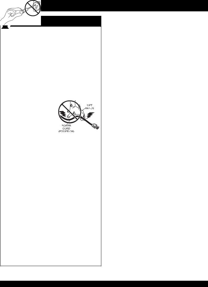
NEVER grab or touch a live power cord with wet hands, the possibility exist of electrical shock, electrocution, and even death!
NEVER insert any objects into the output receptacles during operation. This is extremely dangerous. ALWAYS turn-off
the generators and place all circuit breakers in the “OFF” position when contact with the output receptacles is required. There exist the possibility of electrocution, electrical shock or burn, which can cause severe bodily harm or even death!
Backfeed to a utility system can cause electrocution and or property damage. NEVER connect the generators to a building's electrical system without a transfer switch or other approved device. All installations should be performed by a licensed electrician in accordance with all applicable laws and electrical codes. Failure to do so could result in electrical shock or burn causing serious injury or even death!
Emergencies
■ALWAYS know the location of the nearest fire extinguisher.
■ALWAYS know the location of the nearest first aid kit.
■In emergencies always know the location of the nearest phone or keep a phone on the job site. Also know the phone numbers of the nearest ambulance, doctor and fire department. This information will be invaluable in the case of an emergency.
PAGE 10 — GA-6H/GA-6HA A.C. GENERATORS — OPERATION & PARTS MANUAL — REV. #0 (06/02/05)

GA-6H/GA-6HA — OPERATION AND SAFETY DECALS
Machine Safety Decals
The GA-6H/GA-6HA portable generators are equipped with a number of safety decals (Figure 1).These decals are provided for operator safety and maintenance information.The illustration below shows these decals as they appear on the machine.Should any of these decals become unreadable, replacements can be obtained from your dealer.
Figure 1. Operation and Safety Decals
GA-6H/GA-6HA A.C. GENERATORS — OPERATION & PARTS MANUAL — REV. #0 (06/02/05) — PAGE 11

GA-6H/GA-6HA — SPECIFICATIONS (GENERATORS)
Table 1. Specifications (Generators)
|
Model |
GA-6H/GA-6HA |
|
|
|
|
|
|
Type |
Brushless Revolving Field Type |
|
|
|
|
|
AC Generator |
Excitation |
Solid State, Statically Excited System |
|
|
|
||
Speed |
3,600 RPM |
||
|
|||
|
|
|
|
|
Cooling System |
Self-Ventilation |
|
|
|
|
|
|
Fuel Capacity |
5 gallons (19 liters) |
|
|
|
|
|
|
Continuous Output |
5.0 kW |
|
|
|
|
|
|
Stanby Output |
6.0 kW |
|
|
|
|
|
|
Rated Voltage |
120/240V |
|
|
|
|
|
60 Cycle AC Power |
Current Max/Continuous (120V) |
50.0/41.6 amps |
|
|
|
||
Source |
Current Max/Continuous (240V) |
25.0/20.8 amps |
|
|
|||
|
|
|
|
|
Phase |
Single Phase (4 wire) |
|
|
|
|
|
|
Frequency |
60 Hz |
|
|
|
|
|
|
Power Factor |
1 |
|
|
|
|
|
Dimensions |
|
25.6 x 22.6 X 21.3 in. |
|
(L x W x H) |
|
(650 X 560 X 540 mm) |
|
|
|
|
|
Dry Net Weight |
|
201 lbs. (91 kg.) |
|
|
|
|
|
Weight (With Fuel) |
|
227 lbs. (103 kg.) |
|
|
|
|
Effects of Altitude and Heat
The maximum output of the engines listed above are applicable to supplying electrical power for continuous service at ambient conditions in accordance with SAE Test cord J607. The above ambient conditions are at standard sea level, with a barometric reading of 29.92 inches and a temperature of 60 degrees fahrenheit.
Generally, the engine's output power will decrease 3-1/2% for each 1000 feet of altitude above sea level, and 1% for each 10° F Fahrenheit above the standard temperature of 60° F
PAGE 12 — GA-6H/GA-6HA A.C. GENERATORS — OPERATION & PARTS MANUAL — REV. #0 (06/02/05)

GA-6H/GA-6HA — SPECIFICATIONS (ENGINE)
Table 2. Specifications (Engine)
|
Model |
HONDA GX340K1EDN2 |
|
|
|
|
|
Air-cooled 4 stroke, Single |
|
Type |
Cylinder, OHV, |
|
Horizontal Shaft Gasoline |
|
|
|
|
|
|
Engine |
|
|
|
|
Bore X Stroke |
2.90 in. X 2.30 in. |
|
(73 mm x 58 mm.) |
|
|
|
|
|
|
|
Engine |
Displacement |
23.70 cu-in (389 cm3) |
|
|
|
|
Max Output |
11.0 H.P./3600 R.P.M. |
|
|
|
|
Fuel |
Unleaded Automobile Gasoline |
|
|
|
|
Lube Oil Capacity |
1.16 quarts (1.1 liters) |
|
|
|
|
Oil Alert System |
Yes |
|
|
|
|
Speed Control Method |
Centrifugal Fly-weight Type |
|
|
|
|
Starting Method |
Recoil Start |
|
|
|
Dimension |
|
15.0 x 17.7 X 17.4 in. |
(L x W x H) |
|
(380 X 450 X 443 mm.) |
|
|
|
Dry Net Weight |
|
68.4 lbs (31 Kg.) |
|
|
|
In keeping with Multiquip's policy of constantly improving its products, the specifications quoted herein are subject to change without prior notice.
GA-6H/GA-6HA A.C. GENERATORS — OPERATION & PARTS MANUAL — REV. #0 (06/02/05) — PAGE 13
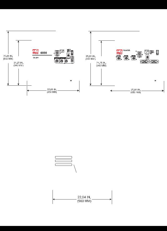
GA-6H/GA-6HA — DIMENSIONS
Figure 2. Dimensions
PAGE 14 — GA-6H/GA-6HA A.C. GENERATORS — OPERATION & PARTS MANUAL — REV. #0 (06/02/05)

GA-6H/GA-6HA — GENERAL INFORMATION
 WARNING
Before connecting this generators to any building’s electrical system, a licensed electrician must install an isolation (transfer) switch.
Serious injury or death may result without this transfer switch.
GA-6H/GA-6HA FAMILIARIZATION
Generator
The Multiquip GA-6H and GA-6HA generators have been designed as a portable dual purpose power source for 60 Hz (single phase) lighting facilities, power tools, submersible pumps and other industrial and construction machinery.
These generators are mounted on rubber vibration isolators that have a steel base backplate which is attached to the protective steel pipe carrying frame.The protective carrying frame is made of steel tubing and fully wraps around the generators to protect against damage. See Figures 3A through 3E for the basic controls and indicators for the GA-
6H/GA-6HA generators.
These portable generators are supplied with a electrical control box. To reduce vibration caused by the engine, the control box is also placed on rubber isolators.
Control Box
The control box is provided with the following:
■120/240V twist-lock output receptacle (single phase).
■120V twist-lock receptacle (2) (single phase).
■120V GFCI single phase duplex output receptacle (GA6HA has two).
■21 amp main circuit breaker.
■AC Voltmeter
■Ground Terminal
■Full Power Switch
■Idle Control Switch
■Operation Switch
Excitation System
The GA-6H/GA-6HA-series generators use a magnet attached to a flywheel to produce AC voltage from a lamp coil beneath the flywheel. As the magnetic passes the coil it produces approximately 19-22 AC volts.
This voltage (19-22 VAC) is then sent to the control box that contains three rectifying diodes:
zExcitation (diode 1)
zBattery (diode 2)
zSlow Down (diode 3)
The AC voltage will pass through the excitation diode that converts the voltage to DC power.
This DC power is then sent to the excitation windings housed within the main windings commonly called the "stator".
This voltage is then transferred into the rotor through induction.The rotor contains two diodes within it which rectify the DC voltage and send it out through the main windings, as AC voltage.
Alternator
The alternator, a brushless revolving-field type, is permanently aligned to the engine through rigid coupling.
Engine
These generators are powered by a 11 HP, air-cooled, 4- stroke HONDA gasoline engine. Reference Table 2, for engine specifications.
GA-6H/GA-6HA A.C. GENERATORS — OPERATION & PARTS MANUAL — REV. #0 (06/02/05) — PAGE 15
GA-6H/GA-6HA — LOAD APPLICATION
Single Phase Load — 60 Hz
Always be sure to check the nameplate on the generators and equipment to insure the wattage, amperage and frequency requirements are satisfactorily supplied by the generators for operating the equipment.
Generally, the wattage listed on the nameplate of the equipment is its rated output. Equipment may require 130— 150% more wattage than the rating on the nameplate, as the wattage is influenced by the efficiency, power factor and starting system of the equipment.
If wattage is not given on the equipment's name plate, approximate wattage may be determined by multiplying nameplate voltage by the nameplate amperage.
WATTS = VOLTAGE x AMPERAGE
The power factor of this generators is 1.0 See Table 3 below when connecting loads.
Table 3. Power Factor By Load
Type Of Load |
Power Factor |
|
|
|
|
Single-phase induction motors |
0.4 - 0.75 |
|
|
|
|
Electric heaters, incandescent |
1.0 |
|
lamps |
||
|
||
|
|
|
Fluorescent lamps, mecury |
0.4 - 0.9 |
|
lamps |
||
|
||
|
|
|
Electronic devices, |
1.0 |
|
communication equipment |
||
|
||
|
|
|
Common power tools |
0.8 |
|
|
|
When using a combination of dual receptacles, total load should not exceed the rated capacity of the generator.
To determine the running wattage for your load, multiply the running wattage as indicated by steps 1, 2, and 3 below:
1.INCANDESCENT LOADS
Lights, heaters and similar appliances. Total the running wattage and multiply by 1. Example:
29 light bulbs @ 100W each = 2.9 KW use a 3 KW generator.
2.SMALL MOTORS
Drills and other small power tools.
Total the running wattage and multiply by 2. Example:
A 1 inch drill runs at 1 KW use a 2 KW generator.
3.LARGE MOTORS
Submersible pumps, table saws etc.
Total the running wattage and multiply by 3. Example:
A conveyor belt runs at 8 KW use a 24 KW generator.
 CAUTION
Motors and motor-driven equipment draw much greater current for starting than during operation. Always use an adequate size extension cable which can carry the required load.
Extension Cables
When electric power is to be provided to various tools or loads at some distance from the generator, extension cords are normally used. Cables should be sized to allow for distance in length and amperage so that the voltage drop between the generators and point of use (load) is held to a minimum. Use the cable selection chart (Tables
4 and 5 ) as a guide for selecting proper cable size.
The idle control device is operated at a minimum load capacity of 100W. If the load capacity is less than 100W, place the idle control switch in the OFF position.
PAGE 16 — GA-6H/GA-6HA A.C. GENERATORS — OPERATION & PARTS MANUAL — REV. #0 (06/02/05)
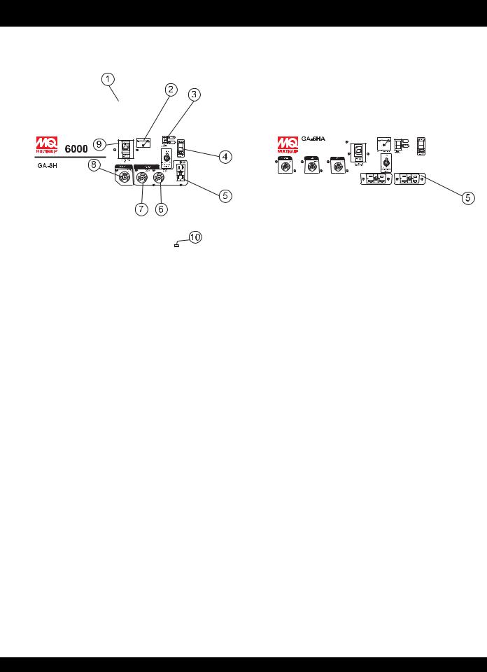
GA-6H/GA-6HA — CONTROLS AND INDICATORS
Figure 3A. Generators Components
1. |
Lifting Bail Eye – Attach a rope or chain to this lifting eye |
|
when lifting of the generators is required. Never stand |
|
underneath the generators while it is being lifted. Place |
|
lifting eye in down position when not in use. |
2. |
AC-Voltmeter – This voltmeter indicates (with a mark) the |
|
rated 60 Hz (single-phase) output voltage. In addition the |
|
voltmeter can also be used as a diagnostic tool. If the |
|
voltmeter indicator (needle) is below the rated voltage, |
|
engine problems may exist (low/high RPM's). To prevent |
|
damage to the generators or power tools turn the generators |
|
OFF and consult your authorized Multiquip service dealer. |
3. |
Idle Control Switch – The generators are provided with |
|
an automatic idle control device for noise suppression and |
|
reduced fuel consumption. The automatic idle control |
|
automatically engages under a no-load condition. With the |
automatic idle control switched “ON”, the engine revolutions will automatically drop to about 2600 rpm (low-speed operation) within 3 seconds after the load stops. When the operation is resumed, the engine speed is automatically increased to about 3600 rpm (high-speed operation) as soon as the load is connected.
5.GFCIDuplexReceptacle– NEMA 5-20R, GFCI receptacle will provide 120V, 20 amps. (GA-6HA has two.)
6. |
120V Output Receptacle – NEMA L5-20R twist-lock |
|
receptacle will provide 120V, 20 amps, 60 Hz. |
7. |
120V Output Receptacle – NEMA L5-30R twist-lock |
|
receptacle will provide 120V, 30 amps, 60 Hz. |
8. |
120V/240V Output Receptacle – NEMA L14-30R twist- |
|
lock receptacle will provide (120V, 50 amps, or 240V, |
|
25 amps, 60 Hz.) |
9. |
Main Breaker – This 2-pole circuit breaker (120/240V, 21 |
|
amps) protects the generators from short circuiting or |
|
overloading. When starting the generators always have |
|
the circuit breaker placed in the "OFF" position. |
10. |
Ground – This ground connection point should be |
|
connect to a good earth ground (ground rod) |
4. Operation Switch – Place this rocker switch in the "ON" position (up) for normal operation.To turn-off the generators, place the operation switch in the "OFF" position (down).
GA-6H/GA-6HA A.C. GENERATORS — OPERATION & PARTS MANUAL — REV. #0 (06/02/05) — PAGE 17
GA-6H/GA-6HA — CONTROLS AND INDICATORS
Figure 3B. Generators Components
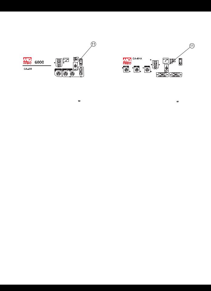
11. Full Power Switch – The generators are provided with a full power switch. Figures 3C and 3D show simplified wiring diagrams of the dual voltage system.
When the full power switch is in the 120 volt (up) position, you can access the full rated power of the generators at 120 volts from the GFCI duplex receptacle and the120V twist-lock receptacle, or a combination of both receptacles as long as the total load does not exceed the generating set capacity.
When the switch is in the 240 volt (down) position, you can acess half of the rated power of the generating set at 120 volts from the GFCI duplex receptacle and up to half of the rated power of the set at 120 volts from 120V twist-lock receptacle; or full rated power of the set at 240 volts from the 240V twist-lock receptacle.
|
Figure 3D. 120/240V Full Power Switch |
Figure 3C. 120V Full Power Switch |
Simplified Diagram (Down Position) |
Simplified Diagram (Up Position) |
|
When the full power switch is in the 120V position, the 240V twist-lock receptacle cannot be used.
PAGE 18 — GA-6H/GA-6HA A.C. GENERATORS — OPERATION & PARTS MANUAL — REV. #0 (06/02/05)
GA-6H/GA-6HA — CONTROLS AND INDICATORS
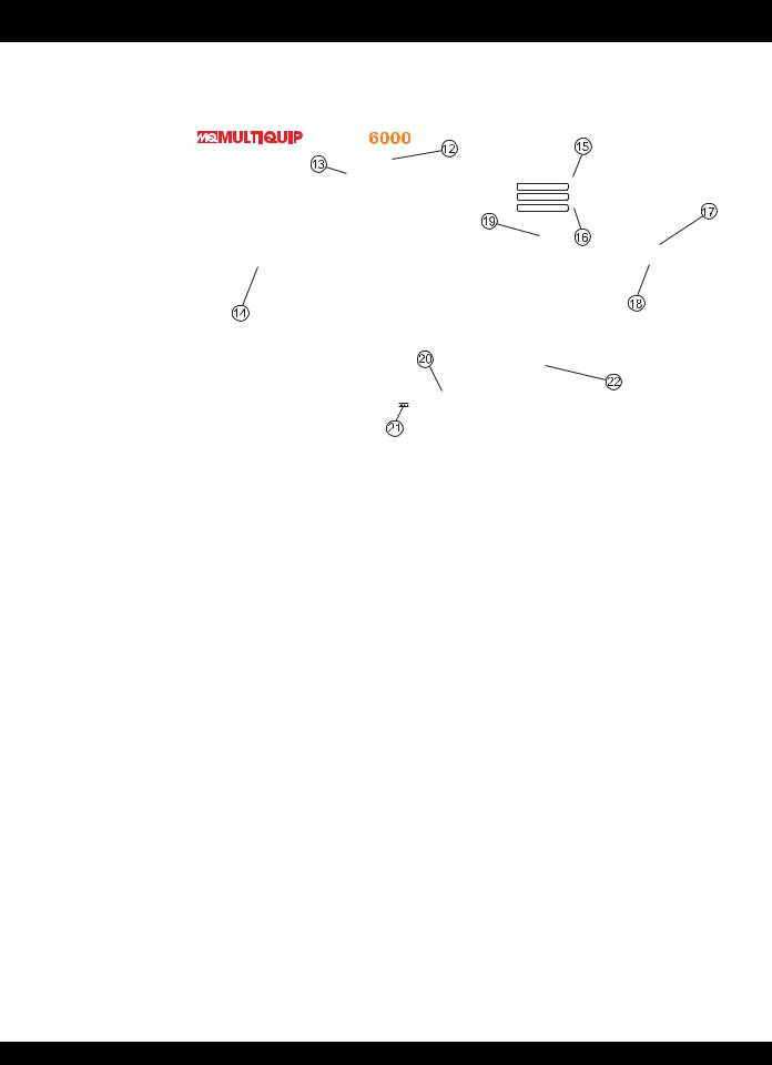
Figure 3E. Generators Components
12. Fuel Cock Lever – Turn this lever downward to start (down)the flow of fuel into the carburetor.Turn upward to stop (up) the flow of fuel.
13. Spark Plug – Provides spark to the ignition system. Set spark plug gap to 0.6 - 0.7 mm (0.028 - 0.031 inch) Clean spark plug once a week.
14. Muffler/HeatShield– Used to reduce noise and emissions. NEVER touch this heat shield when the generator/welder is in use. Always allow time for the generators to cool down before performing maintenance.
15. Choke Lever – Used for starting the engine. Close the choke lever when starting a cold engine or in cold weather conditions.The choke enriches the fuel mixture.Open the choke lever if starting a warm engine or in warm weather conditions.
16. Recoil Starter (pull rope) – Manual-starting method. Pull the starter grip until resistance is felt, then pull briskly and smoothly.
17.Engine Oil Filler Cap – Remove this cap/dipstick when the adding of engine oil is required. See Table 5 for recommended type engine oil.
18.Engine Oil Drain Plug – Remove this drain plug when draining of the oil from the engine crankcase is required. Fill with recommeded type oil as listed in Table 6.
19. Air Cleaner – Prevents dirt and other debris from entering the fuel system. Remove wing-nut on top of air filter cannister to gain access to filter element. NEVER run the engine without an air cleaner.
20. Fuel Tank Cap – Remove this cap to add unleaded gasoline to the fuel tank. Replenish with clean unleaded gasoline. Make sure cap is tightened securely. DO NOT over fill.
21. Fuel Gauge – This gauge is located on top of the fuel tank. Read this gauge to determine when fuel is low.
22. FuelTank – Fuel tank capacity is 5 gallons (19 liters).
This HONDA engine is equipped with a low oil shutdown capability. A built in sensor will automatically turn off the engine should the oil level fall below a safe operating condition. Make sure the generators is placed
on level ground. Placing the generators on level ground will ensure that the low oil sensor will function properly.
GA-6H/GA-6HA A.C. GENERATORS — OPERATION & PARTS MANUAL — REV. #0 (06/02/05) — PAGE 19
GA-6H/GA-6HA — GENERATOR REFUELING
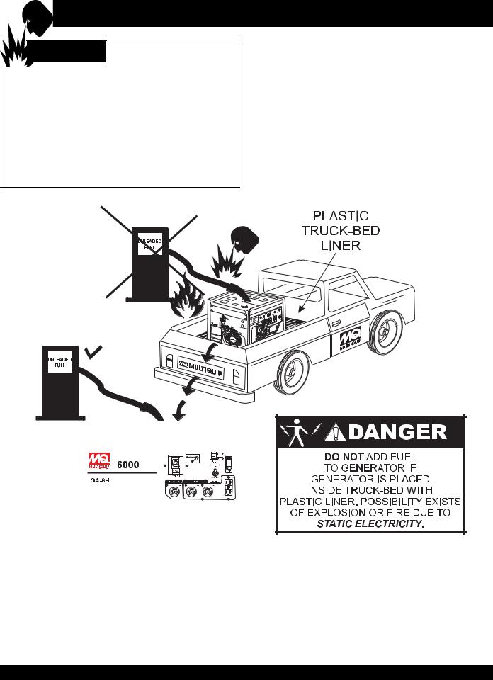
 DANGER
Addingfueltothetankshouldbedoneonlywhen theengineisstoppedandhashadanopportunity to cool down. In the event of a fuel spill, DONOT attempt to start the engine until the fuel residue
has been completely wiped up, and the area surrounding the engine is dry. If generators is placed in a truck bed with a plastic liner, REMOVEgenerators from truck bed and place on ground (Figure4)torefuel.Thispossibilityexistoffireorexplosiondue tostaticelectricity.
Figure 4. Generators Refueling
PAGE 20 — GA-6H/GA-6HA A.C. GENERATORS — OPERATION & PARTS MANUAL — REV. #0 (06/02/05)
Outdoor Installation
Install the generator/welder in a area that is free of debris, bystanders, and overhead obstructions. Make sure the generators is on secure level ground so that it cannot slide or shift around. Also install the generators in a manner so that the exhaust will not be discharged in the direction of nearby homes.
The installation site must be relatively free from moisture and dust. All electrical equipment should be protected from excessive moisture. Failure to do will result in deterioration of the insulation and will result in short circuits and grounding.
Foreign materials such as dust, sand, lint and abrasive materials have a tendency to cause excessive wear to engine and alternator parts.
 CAUTION
Pay close attention to ventilation when operating the generators inside tunnels and caves.The engine exhaust contains noxious elements.
Mounting
The generators should always be mounted on a flat level surface to isolate vibration of the generators when it is running. DO NOT place the generators on slopes, the possibility exists that the generators could slide.
 CAUTION
An electric shock is apt to happen when vibrators are used. Pay close attention to handling when operating vibrators and always use rubber boots and gloves to insulate the body from a short circuit.
GA-6H/GA-6HA — INSTALLATION
Indoor Installation
Exhaust gases from gasoline engines are extremely poisonous. Whenever an engine is installed indoors the exhaust fumes must be vented to the outside. The engine should be installed at least two feet from any outside wall. Using an exhaust pipe which is too long or too small can cause excessive back pressure which will cause the engine to heat excessively and possibly burn the valves.
Eliminate the danger of deadly carbon monoxide gas.
Remember that exhaust fumes from any gasoline engine are very poisonous if discharged in a closed room, but harmless if allowed to mix with the outside air. If the generators is installed indoors, you must make provisions for venting the engine exhaust to the outside of the building.
Generators Grounding
To guard against electrical shock and possible damage to the equipment, it is important to provide a good EARTH ground. Always use the ground terminal on the generators to ground the generator. Ground the generators from its ground connector so that the resistance to ground is 500 ohms or less.
Article 250 (Grounding) of the National Electrical Code (NEC) provides guide lines for proper grounding and specifies that the cable ground shall be connected to the grounding system of the building as close to the point of cable entry as practical.
NEC articles 250-64(b) and 250-66 set the following grounding requirements:
1.Use one of the following wire types to connect the generators to earth ground.
a.Copper - 10 AWG (5.3 mm2) or larger.
b.Aluminum - 8 AWG (8.4 mm2) or larger.
2.When grounding the generators (Figure 3) connect the ground cable between the lock washer and the nut on the generators and tighten the nut fully. Connect the other end of the ground cable to earth ground.
3.NEC article 250-52(c) specifies that the earth ground rod should be buried a minimum of 8 ft. into the ground.
GA-6H/GA-6HA A.C. GENERATORS — OPERATION & PARTS MANUAL — REV. #0 (06/02/05) — PAGE 21
GA-6H/GA-6HA — INSTALLATION
Connecting the Ground
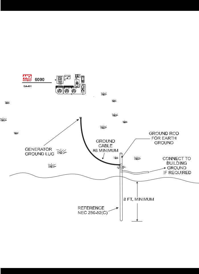
The nut and ground terminal on the generators should always be used to connect the generators to a suitable ground.The ground cable should be #8 size wire minimum.
At the generator, connect the terminal of the ground cable between the lock washer and the nut (Figure 5) and tighten the nut fully. Connect the other end of the ground cable to a suitable earth ground (ground rod).
Figure 5. Generators Grounding
PAGE 22 — GA-6H/GA-6HA A.C. GENERATORS — OPERATION & PARTS MANUAL — REV. #0 (06/02/05)

GA-6H/GA-6HA — PRE-INSPECTION
General Inspection Prior to Operation
Ground Power Tools
When using power tools or electrical equipment requireing AC power from the generator, make sure connecting (power tool) cable (Figure 6) has a ground as shown in Figure.
Figure 6. Ground Cables/Plugs
Extension Cable
When electric power is to be provided to various tools or loads at some distance from the generator, extension cords are normally used. Cables should be sized to allow for distance in length and amperage so that the voltage drop between the generators and point of use (load) is held to a minimum. Use the cable selection chart (Table 4) as a guide for selecting proper cable size.
Never! use power tools or equipment that do not have a ground capability, the possibility exists of electrocution, electrical shock or burn, which can cause severe bodily harm or even
DEATH!
Main Circuit Breaker
To protect the generators from an overload always place the main circuit breaker in the "OFF" position prior to starting the engine.
Table 4. Cable Selection (60 Hz, Single Phase Operation)
Current In |
Load In Watts |
|
|
Maximum Allowable Cable Length |
|
|||||
|
|
|
|
|
|
|
|
|
|
|
Amperes |
120 Volts |
240 Volts |
#10 Wire |
|
#12 Wire |
#14 Wire |
|
#16 Wire |
||
|
|
|
||||||||
|
|
|
|
|
|
|
|
|
|
|
2.5 |
300 |
600 |
1000 ft. |
|
600 |
ft. |
375 ft. |
|
250 ft. |
|
|
|
|
|
|
|
|
|
|
|
|
5 |
600 |
1200 |
500 |
ft. |
|
300 |
ft. |
200 ft. |
|
125 ft. |
|
|
|
|
|
|
|
|
|
|
|
7.5 |
900 |
1800 |
350 |
ft. |
|
200 |
ft. |
125 ft. |
|
100 ft. |
|
|
|
|
|
|
|
|
|
|
|
10 |
1200 |
2400 |
250 |
ft. |
|
150 ft. |
100 ft. |
|
|
|
|
|
|
|
|
|
|
|
|
||
15 |
1800 |
3600 |
150 ft. |
|
100 ft. |
65 ft. |
|
|
||
|
|
|
|
|
|
|
|
|
||
20 |
2400 |
4800 |
125 ft. |
|
75 ft. |
50 ft. |
|
|
||
|
|
|
|
|
|
|
|
|
|
|
CAUTION: Equipment damage can result from low voltage. |
|
|
|
|
|
|
||||
|
|
|
|
|
|
|
|
|
|
|
GA-6H/GA-6HA A.C. GENERATORS — OPERATION & PARTS MANUAL — REV. #0 (06/02/05) — PAGE 23
GA-6H/GA-6HA — PRE-INSPECTION (ENGINE)
 CAUTION
NEVERoperatethegenerators in a confined area or enclosed area structure that does not provide ample free flow of air.
ALWAYS wear approved eye and hearing protection before operating the generator.
Before Starting
1.Read safety instructions at the beginning of manual.
2.Clean the generator, removing dirt and dust, particularly the engine cooling air inlet, carburetor and air cleaner.
3.Check the air filter for dirt and dust. If air filter is dirty, replace air filter with a new one as required.
4.Check carburetor for external dirt and dust. Clean with dry compressed air.
5.Check fastening nuts and bolts for tightness.
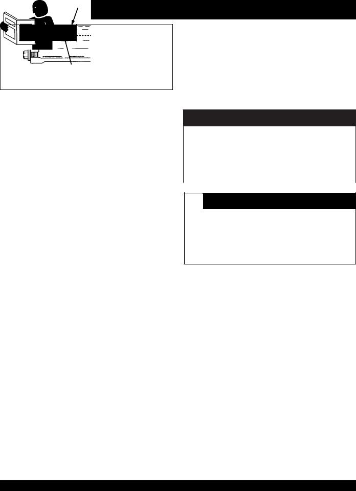
Engine Oil Check
1.To check the engine oil level, place the generators on secure level ground with the engine stopped.
2.Remove the filler dipstick from the engine oil filler hole (Figure 7) and wipe clean.
Figure 7. Engine Oil Dipstick (Removal)
3.Insertandremovethedipstickwithoutscrewingitintothefiller neck. Check the oil level shown on the dipstick.
4.If the oil level is low (Figure 8), fill to the edge of the oil filler hole with the recommended oil type (Table 5).Maximum oil capacity is 1.16 quarts (1.1 liters)
Figure 8. Engine Oil Dipstick (Oil Level)
Table 5. Oil Type
Season |
Temperature |
Oil Type |
|
|
|
Summer |
25°C or Higher |
SAE 10W-30 |
|
|
|
Spring/Fall |
25°C~10°C |
SAE 10W-30/20 |
|
|
|
Winter |
0°C or Lower |
SAE 10W-10 |
|
|
|
 DANGER EXPLOSIVE FUEL
Motor fuels are highly flammable and can be dangerous if mishandled. DO NOT smoke while refueling. DO NOT attempt to refuel the generators if the engine is hot! , running or in the dark.
Fuel Check
1.Close the fuel cock before filling the fuel tank.
2.Remove the fuel cap located on top of fuel tank.
3.Readthefuelgaugelocatedontopofthefueltank(Figure9)to determin if the fuel level is low. If fuel is low, replenish with clean unleaded fuel.
Figure 9. Fuel Gauge
4.When refueling, be sure to use a strainer for filtration. DO NOT top-off fuel. DO NOT fill the tank beyond capacity.
Wipe up any spilled fuel immediately!
PAGE 24 — GA-6H/GA-6HA A.C. GENERATORS — OPERATION & PARTS MANUAL — REV. #0 (06/02/05)

GA-6H/GA-6HA — INITIAL START-UP (ENGINE)
 CAUTION
DO NOT attempt to operate this generators until the Safety, General Information and Inspection sections of this manual have been read and thoroughly understood.
This section is intended to assist the operator with the initial start-up of the portable generator. It is extremely important that this section be read carefully before attempting to use the generators in the field.
Before Starting the Engine
1.Be sure to disconnect all electrical loads from the generators prior to starting the engine.
2.NEVER start the engine with the main circuit breaker in the “ON" position. Always place this circuit breakers
(Figure 10) in the OFF position before starting.
Figure 10. Main Circuit Breaker (OFF Position)
Starting the Engine
1.Place the engine fuel valve lever (Figure 11) to the "ON" position.”
Figure 11. Engine Fuel Valve Lever (ON Position)
2.Placethechokelever (Figure12)inthe"CLOSED"position if starting a cold engine.
Figure 12. Choke Lever
3.Place the choke lever (Figure 12) in the "OPEN " position if starting a warm engine or the temperature is warm.
4.Place thegenerator's operationswitch(Figure13)inthe "ON"position.
Figure 13. Generator On/Off Switch (ON)
5.Grasp the starter grip (Figure 14) and slowly pull it out.The resistancebecomesthehardestatacertainposition,corresponding to the compression point. Pull the starter grip briskly and smoothly for starting.
Figure 14. Starter Grip
 CAUTION
DO NOT pull the starter rope all the way to the end.
DO NOT release the starter rope after pulling. Allow it to rewind as soon as possible.
GA-6H/GA-6HA A.C. GENERATORS — OPERATION & PARTS MANUAL — REV. #0 (06/02/05) — PAGE 25
GA-6H/GA-6HA — INITIAL START-UP/GENERATOR OPERATION
6.If the engine has started, slowly return the choke lever (Figure 12 ) to the “OPEN” position. If the engine has not started repeat steps 1 through 5.
7.Before the generators is placed into operation, run the engine for 3-5 minutes. Check for abnormal smells, fuel leaks, and noises that would associate with lose components.
8.Place the idle control switch (Figure 15) in the "OFF" (down) position. This will allow the engine speed to run at speed about 3600 RPM's
Figure 15. Idle Control Switch (Off)
Placing the idle control switch in the OFF position (Figure 15) allows the engine to operate at a maximum speed of about 3600 RPM's. When the idle control switch is placed in the up position (ON) (Figure 16),
the generators will run at idle speed (2200 RPM's) until a load is applied, at that time the engine speed will increase to 3600 RPM's as long as the load is being applied. When the load is not in use, the engine speed will drop back to the idle mode after about 3 seconds.
Figure 16. Idle Control Switch (On)
60 Hz Operation
1. Place main circuit breaker (Figure 17) in the ON position.
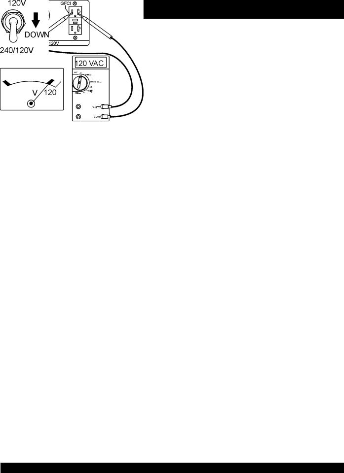
2.Place the full power switch (Figure 18) in the 120V position (up).
Figure 18. Full Power Switch 120 V Position (Up)
When the full power switch is in the 120 V position, the 240V twist-lock receptacle cannot be used.
3.Read the voltmeter on the front panel of the generators
(Figure 19) and verify that120 VAC is present at the
120V twist-lock and GFCI duplex receptacles. For additional verification of voltage, an external voltmeter can be used to measure the output voltage as shown in
Figure 19.
Figure 19. 120 V and GFCI Receptacles
4.Place the full power switch (Figure 20) in the 240V position (down).
Figure 17. Main Circuit Breaker (ON) |
Figure 20. Full Power Switch 240/120 V Position (Down) |
PAGE 26 — GA-6H/GA-6HA A.C. GENERATORS — OPERATION & PARTS MANUAL — REV. #0 (06/02/05)
 Loading...