


OPERATION AND PARTS MANUAL
WHISPERWATTTM SERIES
MODEL DCA10SPX4
MODEL DCA10SPXU4
50 Hz GENERATORS
(KUBOTA D1503-M DIESEL ENGINE)
(DCA10SPX4 S/N 3819207~) (DCA10SPXU4 S/N 8710001~)
Revision #0 (08/05/09)
To find the latest revision of this publication, visit our website at: www.mqpower.com
THIS MANUAL MUST ACCOMPANY THE EQUIPMENT AT ALL TIMES.

DCA10SPX4/DCA10SPXU4 — PROPOSITION 65 WARNING
Diesel engine exhaust and some of
PAGE 2 — DCA10SPX4/DCA10SPXU4 — OPERATION AND PARTS MANUAL — REV. #0 (08/05/09)

DCA10SPX4/DCA10SPXU4 — NOTE PAGE
DCA10SPX4/DCA10SPXU4 — OPERATION AND PARTS MANUAL — REV. #0 (08/05/09) — PAGE 3

DCA10SPX4/DCA10SPXU4 —TABLE OF CONTENTS
MQ POWER DCA-10SPX4
WHISPERWATTTM GENERATOR
California Proposition 65 Warning .................................... |
2 |
Table Of Contents ............................................................ |
4 |
Parts Ordering Procedures .............................................. |
5 |
Specifications ................................................................... |
6 |
Dimensions (Top, Side, Front) .......................................... |
7 |
Safety Message Alert Symbols .................................... |
8-9 |
Rules for Safe Operation .......................................... |
10-14 |
Installation ................................................................ |
16-17 |
General Information ....................................................... |
18 |
Major Components ......................................................... |
19 |
Generator Control Panel ................................................ |
20 |
Output Terminal Panel Familiarization ...................... |
21-23 |
Load Application/Maximum Amperage ........................... |
24 |
Setup ........................................................................ |
25-28 |
Generator Start-up Procedure.................................. |
29-30 |
Generator Shut-Down Procedure ................................... |
31 |
Maintenance (Engine) .............................................. |
32-33 |
Maintenance (Trailer)................................................ |
34-36 |
Generator Wiring Diagram.............................................. |
37 |
Engine Wiring Diagram .................................................. |
38 |
Troubleshooting (Engine) ......................................... |
39-40 |
Troubleshooting (Generator) .......................................... |
41 |
Troubleshooting (Pre-heat Lamp Codes) ....................... |
42 |
Explanation of Code in Remarks Column ...................... |
44 |
Suggested Spare Parts .................................................. |
45 |
COMPONENT DRAWINGS
Generator Assembly................................................. |
46-47 |
Control Panel Assembly ........................................... |
48-51 |
Output Receptacle Assembly ................................... |
52-53 |
Engine and Radiator Assembly ................................ |
54-57 |
Battery Assembly (DCA10SPX4) ............................. |
58-59 |
Battery Assembly (DCA10SPXU4)........................... |
60-61 |
Muffler Assembly ...................................................... |
62-63 |
Fuel Tank Assembly ................................................. |
64-65 |
Enclosure Assembly ................................................. |
66-69 |
Rubber Seals Assembly ........................................... |
70-71 |
Nameplate and Decals ............................................. |
72-73 |
Terms and Condition of Sale — Parts ............................ |
74 |
NOTE |
Specifications are subject to |
|
change without notice. |
PAGE 4 — DCA10SPX4/DCA10SPXU4 — OPERATION AND PARTS MANUAL — REV. #0 (08/05/09)
www.mqpower.com

DCA10SPX4/DCA10SPXU4 — PARTS ORDERING PROCEDURES
Ordering parts has never been easier!
Choose from three easy options:
Effective: January
Order via Internet (Dealers Only):
Order parts on-line using Multiquip’s SmartEquip website!
■View Parts Diagrams Order Parts
Goto www.multiquip.com and click on
Order Parts to log in and
save!
If you have an MQ Account, to obtain a Username and Password, E-mail us at: parts@multiquip.com.
To obtain an MQ Account, contact your
Use the internet and qualify for a 5% Discount on Standard orders for all orders which include
Note: Discounts Are Subject To Change
|
|
|
|
|
|
|
|
|
Order via Fax (Dealers Only): |
|
|
|
|
|
|
|
|
|
|
|
|
|
|
|
|
|
|
|
|
|
|
|
|
|
|
|
|
|
|
|
|
|
|
|
|
|
|
|||||||||||||||||||||||||||||||||
|
|
|
|
|
|
|
|
|
|
|
|
Fax your order in and qualify for a 2% Discount |
|
|||||||||||||||||||||||||||||||||||||||||||||||||||||||||||||||||||
|
|
|
|
|
|
|
|
|
|
|
|
|
||||||||||||||||||||||||||||||||||||||||||||||||||||||||||||||||||||
|
|
|||||||||||||||||||||||||||||||||||||||||||||||||||||||||||||||||||||||||||||||
|
|
|
|
|
|
|
|
|
All customers are welcome to order parts via Fax. |
|
|
|
on Standard orders for all orders which include |
|
||||||||||||||||||||||||||||||||||||||||||||||||||||||||||||||||||
|
|
|||||||||||||||||||||||||||||||||||||||||||||||||||||||||||||||||||||||||||||||
|
|
|
|
|
|
|
|
|
|
|
|
|
||||||||||||||||||||||||||||||||||||||||||||||||||||||||||||||||||||
|
|
|||||||||||||||||||||||||||||||||||||||||||||||||||||||||||||||||||||||||||||||
|
|
|
|
|
|
|
|
|
Domestic (US) Customers dial: |
|
|
|
|
|
|
|
|
|
|
|
|
|
|
|
|
|
|
|
|
|
|
|
|
|
|
|
|
|
|
|
|
|
|
|
|
|
|
|||||||||||||||||||||||||||||||||
|
|
|
|
|
|
|
|
|
|
|
|
|
|
|
|
|
|
|
|
|
|
|
|
|
|
|
|
|
|
|
|
|
|
|
|
|
|
|||||||||||||||||||||||||||||||||||||||||||
|
|
|
|
|
|
|
|
|
|
|
|
|
|
|
|
|
|
|
|
|
|
|
|
|
|
|
|
|
|
|
|
|
|
|
|
|
|
|
|
|
|
|
|
|
|
|
|
|
|
|
|
|
|
|
|
|
|
|
|
|
|
|
|
|
|
|
|
|
|
|
|
|
|
|
|
|
|
|
|
|
|
|
|
|
|
|
|
|
|
|
|
|
|
|
|
|
|
|
|
|
|
|
|
|
|
|
|
|
|
|
|
|
|
|
|
|
|
|
|
|
|
|
|
|
|
|
|
|
|
|
|
|
|
|
|
|
|
|
|
|
|
|
Note: Discounts Are Subject To Change |
|
|||||||||||||||||
|
|
|
|
|
|
|
|
|
|
|
|
|
|
|
|
|
|
|
|
|
|
|
|
|
|
|
|
|
|
|
|
|
|
|
|
|
|
|
|
|
|
|
|
|
|
|
|
|
|
|
|
|
|
|
|
|
|
|
|
|
|
|
||||||||||||||||||
|
|
|
|
|
|
|
|
|
|
|
|
|
|
|
|
|
|
|
|
|
|
|
|
|
|
|
|
|
|
|
|
|
|
|
|
|
|
|
|
|
|
|
|
|
|
|
|
|
|
|
|
|
|
|
|
|
|
|
|
|
|
|
|
|
|
|
|
|
|
|||||||||||
|
|
|
|
|
|
|
|
|
|
|
|
|
|
|
|
|
|
|
|
|
|
Order via Phone: Domestic (US) Dealers Call: |
|
|||||||||||||||||||||||||||||||||||||||||||||||||||||||||
|
|
|
|
|
|
|
|
|
|
|
|
|
|
|
|
|
|
|
|
|
|
|
||||||||||||||||||||||||||||||||||||||||||||||||||||||||||
|
|
|
|
|
|
|
|
|
|
|
|
|
|
|
|
|
|
|
|
|
|
|
||||||||||||||||||||||||||||||||||||||||||||||||||||||||||
|
|
|
|
|
|
|
|
|
|
|
|
|
|
|
|
|
|
|
|
|
|
|
|
|
|
|
|
|
|
|
|
|
|
|
|
|
|
|
|
|
|
|
|
|
|
|
|
|
|
|
|
|
|
|
|
|
|
|
|
|
|
|
|
|
|
|
|
|
|
|
|
|
|
|
|
|
|
|
|
|
|
|
|
|
|
|
|
|
|
|
|
|
|
|
|
|
|
|
|
|
|
|
|
|
|
|
|
|
|
|
|
|
|
|
|
|
|
|
|
|
|
|
|
|
|
|
|
|
|
|
|
|
|
|
|
|
|
|
|
|
|
|
|
|
|
|
|
|
|
|
|
|
|
|
|
|
|
|
|
|
|
|
|
|
|
Non-Dealer Customers: |
|
|
|
|
|
|
|
|
|
International Customers should contact |
|
|
|
|
|
|||||||||||||||||||||||||||||||||||||||||||||||||||||||||||||
|
|
|
|
|
|
|
|
|
|
|
|
|
||||||||||||||||||||||||||||||||||||||||||||||||||||||||||||||||||||
|
|
|
|
|
|
|
|
|
|
|
|
|
||||||||||||||||||||||||||||||||||||||||||||||||||||||||||||||||||||
|
|
|
|
Contact your local Multiquip Dealer for |
|
|
|
|
|
|
|
|
|
|
|
|
|
|
|
|
|
|
|
|
||||||||||||||||||||||||||||||||||||||||||||||||||||||||
|
|
|
|
|
|
|
|
|
|
|
|
|
|
|
|
|
|
|
|
|
|
|
|
|
|
|
||||||||||||||||||||||||||||||||||||||||||||||||||||||
|
|
|
|
|
|
|
|
|
|
|
|
|
|
|
|
|
their local Multiquip Representatives for |
|
|
|
|
|
||||||||||||||||||||||||||||||||||||||||||||||||||||||||||
|
|
|
|
parts or call 800-427-1244 for help in |
|
|
|
|
|
|
|
|
|
|
|
|
|
|
|
|
|
|
|
|
||||||||||||||||||||||||||||||||||||||||||||||||||||||||
|
|
|
|
|
|
|
|
|
|
|
|
|
|
|
|
|
|
|
|
|
|
|
||||||||||||||||||||||||||||||||||||||||||||||||||||||||||
|
|
|
|
|
|
|
|
|
|
|
|
|
|
|
|
|
|
|
|
|
|
|
|
|
|
|
|
|
|
|
|
|
|
|
|
|
|
|
|
|
|
|
|
|
|
|
|
|
|
|
||||||||||||||||||||||||||||||
|
|
|
|
|
|
|
|
|
|
|
|
|
|
|
|
|
|
|
|
|
|
|
|
|
|
|
|
|
|
|
|
|
|
|
|
|
|
|
|
|
|
|
|
|
|
|
|
|
|
|
|
|
|
|
|
|
|
|
|
|
|
|
|
|
|
|
|
|
|
|||||||||||
|
|
|
|
|
|
|
|
|
|
|
|
|
|
|
|
|
|
|
|
|
|
|
|
|
|
|
|
|
|
|
|
|
|
|
|
|
|
|
|
|
|
|
|
|
|
|
|
|
|
|
|
|
|
|
|
|
|
|
|
|
|
|
|
|
|
|
|
|
|
|
|
|
|
|
|
|
|
|
|
|
|
|
|
|
|
|
|
|
|
|
|
|
|
|
|
|
|
|
|
|
|
|
|
|
|
|
|
|
|
|
|
|
|
|
|
|
|
|
|
|
|
|
|
|
|
|
|
|
|
|
|
|
|
|
|
|
|
|
|
|
|
|
|
|
|
|
|
|
|||||||||||||
|
|
|
|
|
|
|
|
|
|
|
|
|
|
When ordering parts, please supply: |
|
|||||||||||||||||||||||||||||||||||||||||||||||||||||||||||||||||
|
Dealer Account Number |
Specify Preferred Method of Shipment: |
|
|
Dealer Name and Address |
UPS/Fed Ex |
DHL |
|
Shipping Address (if different than billing address) |
Priority One |
Truck |
Ground |
|
||
|
Return Fax Number |
|
|
Next Day |
|
||
|
|
|
|
Applicable Model Number
AllordersaretreatedasStandardOrders and will ship the same day if received
WE ACCEPT ALL MAJOR CREDIT CARDS!
DCA10SPX4/DCA10SPXU4 — OPERATION AND PARTS MANUAL — REV. #0 (08/05/09) — PAGE 5

DCA10SPX4/DCA10SPXU4 — SPECIFICATIONS
|
Table 1. Generator Specifications |
|
|
|
|
Model |
DCA10SPX4/DCA10SPXU4 |
|
|
|
|
Type |
Revolving field, self ventilated, open protected type synchronous |
|
generator |
||
|
||
|
|
|
Phase |
Single Phase |
|
|
|
|
Standby Output |
8.8 KW |
|
|
|
|
Prime Output |
8 KW |
|
|
|
|
Voltage |
200V/100 |
|
|
|
|
Frequency |
50 Hz |
|
|
|
|
Speed |
1500 rpm |
|
|
|
|
Power Factor |
1.0 |
|
|
|
|
Sound Level dB(A) |
61 |
|
@23 ft. (7 meters) |
||
|
||
|
|
|
Approx. Dry Weight |
1,107 lbs. (502 kg.) |
|
|
|
|
Approx. Wet Weight |
1,250 lbs. (567 kg.) |
|
|
|
|
|
Table 2. Engine Specifications |
|
|
|
|
Model |
KUBOTA D1503-M |
|
|
|
|
Type |
4 Cycle, water-cooled, swirl combustion chamber type |
|
|
|
|
No. of Cylinders |
3 cylinders |
|
|
|
|
Bore x Stroke |
3.27 in. x 3.64 in. (83 mm x 92.4 mm) |
|
|
|
|
Rated Speed |
1500 rpm |
|
|
|
|
Displacement |
91.4 cu. in. (1,498 cc) |
|
|
|
|
Starting |
Electric |
|
|
|
|
Coolant Capacity |
1.85 gal. (7 liters) |
|
|
|
|
Lube Oil Capacity |
1.48 gal. (5.6 liters) |
|
|
|
|
Fuel Tank Capacity |
16.4 gal. (62 liters) |
|
|
|
|
Fuel Consumption |
0.79 gal. (3.0 L)/hr at full load |
|
|
|
|
Battery |
12V 65Ah x 1 |
|
|
|
|
Fuel |
#2 Diesel Fuel |
|
|
|
PAGE 6 — DCA10SPX4/DCA10SPXU4 — OPERATION AND PARTS MANUAL — REV. #0 (08/05/09)
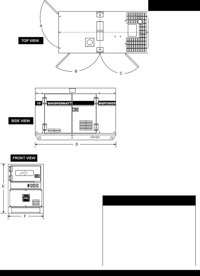
DCA10SPX4/DCA10SPXU4 — DIMENSIONS (TOP, SIDE AND FRONT)
Figure 1.
TABLE 3. DIMENSIONS
Reference Letter |
Dimension ft. (mm.) |
|
|
A |
21.65 in. (550 mm.) |
|
|
B |
19.29 in. (490 mm.) |
|
|
C |
18.50 in. (470 mm.) |
|
|
D |
55.12 in. (1,400 mm.) |
|
|
E |
35.43 in. (900 mm.) |
|
|
F |
26.00 in. (650 mm.) |
|
|
DCA10SPX4/DCA10SPXU4 — OPERATION AND PARTS MANUAL — REV. #0 (08/05/09) — PAGE 7
DCA10SPX4/DCA10SPXU4 — SAFETY MESSAGE ALERT SYMBOLS
FOR YOUR SAFETY AND THE SAFETY OF OTHERS! |
|
HAZARD SYMBOLS |
|
|
|
Safety precautions should be followed at all times when operating this equipment. Failure to read and understand the Safety Messages and Operating Instructions could result in injury to yourself and others.
|
This Owner's Manual has been |
|
NOTE |
developed to provide complete |
|
instructions for the safe and |
||
|
||
|
efficient operation of the |
|
|
MQ Power Generator. |
Before using this generator, ensure that the operating individual has read and understands all instructions in this manual.
SAFETY MESSAGE ALERT SYMBOLS
The three (3) Safety Messages shown below will inform you about potential hazards that could injure you or others. The
Safety Messages specifically address the level of exposure to the operator, and are preceded by one of three words:
DANGER, WARNING, or CAUTION.
DANGER
You WILL be KILLED or SERIOUSLY injured if you do not follow directions.
WARNING
You COULD be KILLED or SERIOUSLY injured if you do not follow directions.
CAUTION
You CAN be injured if you do not follow directions
Potential hazards associated with the operation of this equipment will be referenced with "Hazard Symbols" which appear throughout this manual, and will be referenced in conjunction with Safety "Message Alert Symbols".
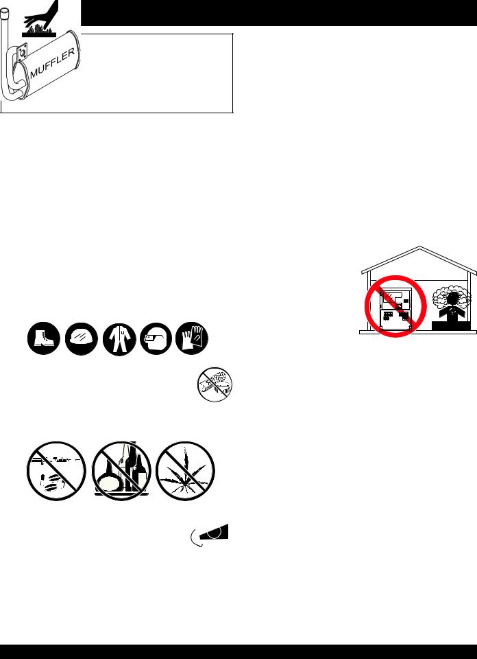
WARNING - LETHAL EXHAUST GASES
Gasoline engine exhaust gases contain poisonous carbon monoxide. This gas is colorless and odorless, and can cause
DEATH if inhaled. NEVER operate this equipment in a confined area or enclosed structure that does not provide ample free flow air.
WARNING - EXPLOSIVE FUEL
Diesel fuel is extremely flammable, and its vapors can cause an explosion if ignited. DO NOT start the engine near spilled fuel or combustible fluids.
DO NOT fill the fuel tank while the engine is running or hot.
DO NOT overfill tank, since spilled fuel could ignite if it comes into contact with hot engine parts or sparks from the ignition system. Store fuel in approved containers, in well-ventilated areas and away from sparks and flames.
NEVER use fuel as a cleaning agent.
WARNING - BURN HAZARDS
Engine components can generate extreme heat.To prevent burns, DO NOT touch these areas while the engine is running or immediately after operations. NEVER operate the engine with heat shields or heat guards removed.
DANGER - ELECTROCUTION HAZARDS
During operation of this generator, there exists the possibility of electrocution, electrical shock or burn,which can cause severe bodily harm or even DEATH!
PAGE 8 — DCA10SPX4/DCA10SPXU4 — OPERATION AND PARTS MANUAL — REV. #0 (08/05/09)
DCA10SPX4/DCA10SPXU4 — SAFETY MESSAGE ALERT SYMBOLS
WARNING - ROTATING PARTS
NEVER operate equipment with covers, or guards removed. Keep fingers, hands, hair and clothing away from all moving parts to prevent injury.
CAUTION - ACCIDENTAL STARTING
ALWAYS place the engine ON/OFF switch (MPEC) in the OFF/RESET position when the generator is not in use.
CAUTION - OVER-SPEED CONDITIONS
NEVER tamper with the factory settings of the engine governor or settings.
Personal injury and damage to the engine or equipment can result if operating in speed ranges above maximum allowable.
This generator, other property, or the surrounding environment could be damaged if you do not follow instructions.
CAUTION - RESPIRATORY HAZARDS
ALWAYS wear approved respiratory protection.
CAUTION - SIGHT AND HEARING HAZARDS
ALWAYS wear approved eye and hearing protection.
CAUTION - EQUIPMENT DAMAGE MESSAGES
Other important messages are provided throughout this manual to help prevent damage to your generator, other property, or the surrounding environment.
CAUTION - ENGINE LOAD (WET-STACKING)
Wet-Stacking is a common problem with diesel engines which are operated for extended periods with light or no load applied. When a diesel engine operates without sufficient load (less than 40% of the rated output) it will not operate at its optimum temperature. This will allow unburned fuel to accumulate in the exhaust system, which can foul the fuel injectors, engine valves and exhaust system, including turbocharges, and reduce the operating performance.
In order for a diesel engine to operate at peak efficiency it must be able to provide fuel and air in the proper ratio and at a high enough engine temperature for the engine to completely burn all of the fuel.
Wet stacking does usually cause any permanent damage and can be alleviated if additional load is applied to relieve the condition. It can reduce the system performance and increase maintenance. Applying an increasing load over a period of time until the excess fuel is burned off and the system capacity is reached usually can repair the condition.
This can take several hours to burn off the accumulated unburned fuel.
DCA10SPX4/DCA10SPXU4 — OPERATION AND PARTS MANUAL — REV. #0 (08/05/09) — PAGE 9
DCA10SPX4/DCA10SPXU4 — RULES FOR SAFE OPERATION
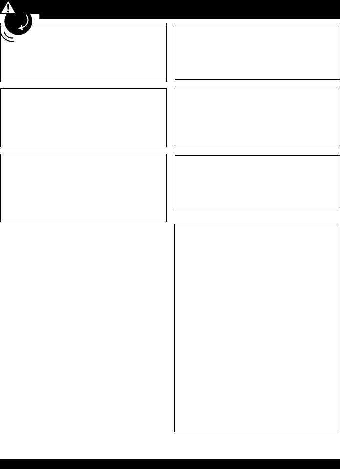
DANGER - READ THIS MANUAL!
Failure to follow instructions in this manual may lead to serious injury or even DEATH! This equipment is to be operated by trained and qualified personnel only! This equipment is for industrial use only.
The following safety guidelines should always be used when operating the generator.
General Safety:
■DO NOT operate or service this equipment before reading this entire manual.
The operator MUST BE familiar with proper safety precautions and operations techniques before using generator.
■This equipment should not be operated by persons under
18 years of age.
■NEVER operate this equipment without proper protective clothing, shatterproof glasses, steel-toed boots and other protective devices required by the job.
■ NEVER operate this equipment when not feeling well due to fatigue, illness or taking medicine.
■NEVER operate this equipment under the influence or drugs or alcohol.
■ALWAYS wear proper respiratory (mask), 


 hearing and eye protection equipment when
  operating the generator.
Whenever necessary, replace nameplate, operation and safety decals when they become difficult read.
Manufacturer does not assume responsibility for any accident due to equipment modifications. Unauthorized equipment modification will void all warranties.
NEVER use accessories or attachments, which are not recommended by Multiquip for this equipment. Damage to the equipment and/or injury to user may result.
NEVER touch the hot exhaust manifold, muffler or cylinder.Allow these parts to cool before servicing engine or generators.
The engine section of this generators requires an adequate free flow of cooling air. NEVER operate the generator in any enclosed or narrow area where free flow of the air is restricted. If the air flow is restricted it will
cause serious damage to |
|
the generators or engine |
|
and may cause injury to |
|
people. Remember the |
|
generator's engine gives |
Denyo |
off DEADLY carbon |
|
monoxide gas. |
DANGEROUS |
GAS FUMES |
ALWAYS refuel in a well-ventilated area, away from sparks and open flames.
ALWAYS use extreme caution when working with flammable liquids. When refueling, stop the engine and allow it to cool. DO NOT smoke around or near the machine. Fire or explosion could result from fuel vapors, or if fuel is spilled on a hot engine.
NEVER operate the generator in an explosive atmosphere or near combustible materials. An explosion or fire could result causing severe bodily harm or even death.
■NEVER disconnect any "emergency or safety devices". These devices are intended for operator safety. Disconnection of these devices can cause severe injury, bodily harm or even death! Disconnection of any of these devices will void all warranties.
PAGE 10 — DCA10SPX4/DCA10SPXU4 — OPERATION AND PARTS MANUAL — REV. #0 (08/05/09)
DCA10SPX4/DCA10SPXU4 — RULES FOR SAFE OPERATION
■ALWAYS be sure the operator is familiar with proper safety precautions and operation techniques before using generators.
NEVER leave the generator unattended, turn off engine when unattended.
Unauthorized equipment modifications will void all warranties.
ALWAYS ensure generator is on level ground before use.
DO NOT place hands or fingers inside generators engine compartment when engine is running.
NEVER run engine without air cleaner.Severe engine damage may occur.
NEVER change or adjust the engine speed which has been set at the factory prior to shipping.
Power Cord Safety
NEVER let power cables or cords lay in water.
NEVER stand in water while AC power from the generators is being transfer to a load.
NEVER use a defective or frayed power cable. Check the cable for cuts in the insulation.
NEVER use a extension cord that is frayed or damaged where the insulation has been cut.
ALWAYS make certain that proper power or extension cord has been selected for the job See Table 6.
Grounding Safety
ALWAYS make sure that electrical circuits are properly grounded per the National Electrical Code (NEC) and local codes before operating generator. Severe injury or death! by electrocution can result from operating an ungrounded generator.
ALWAYS make sure the generators are properly grounded to a suitable earth ground (GROUND ROD). See installation in this manual.
NEVER use gas piping as an electrical ground.
Maintenance Safety
NEVER lubricate components or attempt service on a running machine.
High Temperatures – Always stop engine and allow the engine to cool before adding fuel, oil or performing service and maintenance functions. Contact with hot! components can cause serious burns.
Keep the machinery in proper running condition.
Fix damage to the machine immediately and replace any broken parts immediately.
ALWAYS replace any worn or damaged warning decals.
ALWAYS store equipment properly when it is not being used. Equipment should be stored in a clean, dry location out of the reach of children and un-authorized personnel.
The electrical voltage required to operate the generator can cause severe injury or even death through physical contact with live circuits. Turn all circuit breakers OFF before performing maintenance on the generator.
Dispose of hazardous waste properly. Examples of potentially hazardous waste are used motor oil, fuel and fuel filters.
DO NOT use food or plastic containers to dispose of hazardous waste.
DO NOT pour waste, oil or fuel directly onto the ground, down a drain or into any water source.
ALWAYS allow the machine a proper amount of time to cool before servicing.
ALWAYS service air cleaner frequently to prevent engine malfunction.
ALWAYS disconnect the NEGATIVE battery terminal before performing service on the generator.
Follow all battery safety guidelines listed in this manual when handleing or servicing the generator.
DCA10SPX4/DCA10SPXU4 — OPERATION AND PARTS MANUAL — REV. #0 (08/05/09) — PAGE 11

DCA10SPX4/DCA10SPXU4 — RULES FOR SAFE OPERATION
WARNING - BURN HAZARDS
To prevent burns, DO NOT touch or open any of the below mentioned components while the engine is
running or immediately after operations. Always allow sufficient time for the engine and generator to cool before performing maintenance.
Radiator Cap - Removing the radiator cap while the engine is hot will result in high pressurized, boiling water to gush out of the radiator, causing severe scalding to any persons in the general area of the generator.
Coolant Drain Plug - Removing the coolant drain plug while the engine is hot will result in hot coolant gushing out of the coolant drain plug, therefore causing severe scalding to any persons in the general area of the generator.
Engine Oil Drain Plug - Removing the engine oil drain plug while the engine is hot will result in hot oil gushing out of the oil drain plug, therefore causing severe scalding to any persons in the general area of the generator.
Battery Safety
Use the following guidelines when handling the battery:
The battery contains acids that can cause injury to the eyes and skin. To avoid eye irritation, always wear safety glasses.
Use well insulated gloves when picking up the battery.
DANGER - EXPLOSION HAZARDS
The risk of an explosion exists when performing service on the battery. To avoid severe injury or DEATH:
DO NOT drop the battery.There is the possibility of risk that the battery may explode.
DO NOT expose the battery to open flames, sparks, cigarettes
etc.The battery contains combustible gases and liquids.
If these gases and liquids come in contact with a flame or spark, an explosion could occur.
■ALWAYS keep the battery charged. If the battery is not charged a buildup of combustible gas will occur.
ALWAYS keep battery charging and cables in good working condition. Repair or replace all worn cables.
ALWAYS recharge the battery in an vented air environment, to avoid risk of a dangerous concentration of combustible gases.
In case the battery liquid (dilute sulfuric acid) comes in contact with clothing or skin, rinse skin or clothing immediately with plenty of water.
In case the battery liquid (dilute sulfuric acid) comes in contact with your EYES, rinse eyes immediately with plenty of water and contact the nearest doctor or hospital to seek medical attention.
PAGE 12 — DCA10SPX4/DCA10SPXU4 — OPERATION AND PARTS MANUAL — REV. #0 (08/05/09)
DCA10SPX4/DCA10SPXU4 — RULES FOR SAFE OPERATION
DANGER-Electrocution Hazards
During operation of this generation, there exists the possibility of electrocution, electrical shock or burn, which can cause severe bodily harm or even
DEATH!
To avoid these hazards:
NEVER use damaged or worn cables when connecting equipment to the generator.Make sure power connecting cables are securely connected to the generator’s output receptacles, incorrect connections may cause damage to the generators and electrical shock.
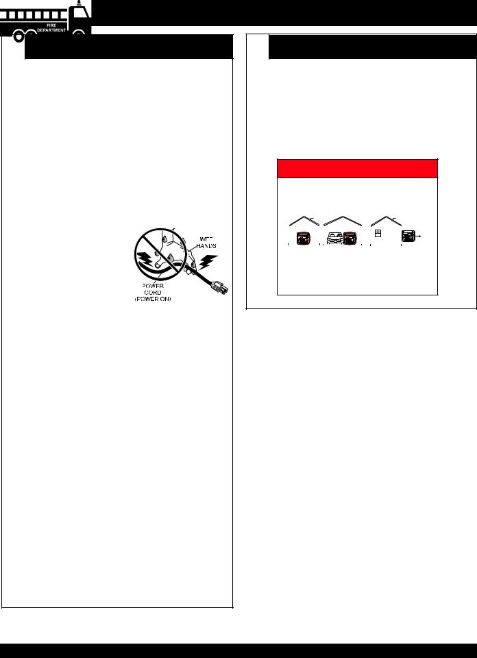
NEVER grab or touch a live power cord with wet hands, the possibility exist of electrical shock, electrocution, and even death!
NEVER insert any objects into the output receptacles during operation. This is extremely dangerous. ALWAYS turn-off
the generators and place all circuit breakers in the “OFF” position when contact with the output receptacles is required. There exist the possibility of electrocution, electrical shock or burn, which can cause severe bodily harm or even death!
Backfeed to a utility system can cause electrocution and or property damage. NEVER connect the generators to a building's electrical system without a transfer switch or other approved device. All installations should be performed by a licensed electrician in accordance with all applicable laws and electrical codes. Failure to do so could result in electrical shock or burn causing serious injury or even death!
DANGER-Lethal Exhaust Gas Hazards
Engine exhaust gases contain poisonous carbon monoxide. This gas is colorless and odorless, and can cause death if inhaled. NEVER operate this equipment in a confined area or enclosed structure that does not provide ample free flow air.
 DANGER
Using a generator indoors CAN KILL YOU IN MINUTES.
Generator exhaust contains carbon monoxide. This is a posion you cannot see or smell
|
|
|
|
|
|
|
|
|
|
|
|
|
|
|
|
|
|
|
|
|
|
|
|
|
|
|
|
|
|
|
|
|
|
|
|
|
|
|
|
|
|
|
|
|
|
|
|
|
|
|
|
|
|
|
|
|
|
|
|
|
|
|
|
|
|
|
|
|
|
|
|
|
|
|
|
|
|
|
|
|
|
|
|
|
|
|
|
|
|
|
|
|
|
|
|
|
|
|
|
|
|
|
|
|
|
|
|
|
|
|
|
|
|
|
|
|
|
|
|
|
|
|
|
|
|
|
|
|
|
|
|
|
|
|
|
|
|
|
|
|
|
|
|
|
|
|
|
|
|
|
|
|
|
|
|
|
|
|
|
|
|
|
|
|
|
|
|
|
|
|
|
|
|
|
|
|
|
|
|
|
|
|
|
|
|
|
|
|
|
|
|
|
|
|
|
|
|
|
|
|
|
|
|
|
|
|
|
|
|
|
|
|
|
|
|
|
|
|
|
|
|
|
|
|
|
|
|
|
|
|
|
|
|
|
|
|
|
|
|
|
|
|
|
|
|
|
|
|
|
|
|
|
|
|
|
|
|
|
|
|
|
|
|
|
|
|
|
|
|
|
|
|
|
|
|
|
|
|
|
|
|
|
|
|
|
|
|
|
|
|
|
|
|
|
|
|
|
|
|
|
|
|
|
|
|
|
|
|
|
|
|
|
|
|
|
|
|
|
|
NEVER use inside a home |
Only use OUTSIDE and |
||||||||||||||||||||||||||||||||||||||
far away from windows, |
|||||||||||||||||||||||||||||||||||||||
or garage, even if doors |
|||||||||||||||||||||||||||||||||||||||
doors, and vents. |
|||||||||||||||||||||||||||||||||||||||
and windows are open |
|||||||||||||||||||||||||||||||||||||||
|
|
|
|
|
|
|
|
|
|
|
|
|
|||||||||||||||||||||||||||
|
|
|
|
|
|
|
|
|
|
|
|
|
|
|
|
|
|
|
|
|
|
|
|
|
|
|
|
|
|
|
|
|
|
|
|
|
|
|
|
Avoid other generator hazards.
READ MANUAL BEFORE USE.
Emergencies
ALWAYS know the location of the nearest fire extinguisher.
ALWAYS know the location of the nearest first aid kit.
In emergencies always know the location of the nearest phone or keep a phone on the job site. Also know the phone numbers of the nearest ambulance, doctor and fire department. This information will be invaluable in the case of an emergency.
DCA10SPX4/DCA10SPXU4 — OPERATION AND PARTS MANUAL — REV. #0 (08/05/09) — PAGE 13
DCA10SPX4/DCA10SPXU4 — RULES FOR SAFE OPERATION
If your generator is trailer mounted, please read the towing and safety requirements listed below.
Towing and Transporting Safety
To reduce the possibility of an accident while transporting the generator on public roads, always make sure the trailer that supports the generator and the towing vehicle are in good operating condition and both units are mechanically sound.
The following list of safety precautions should be followed when towing your generator:
CAUTION - FOLLOW TOWING REGULATIONS
Check with your local county or state safety towing regulations, in addition to meeting Department of Transportation (DOT) Safety Towing Regulations, before towing your generator.
ALWAYS shutdown engine before transporting.
Drain fuel from generator fuel tank before towing.
If generator is mounted on a trailer, make sure trailer complies with all local and state safety transportation laws.
Follow the listed Towing & Transporting Safety guidelines for basic towing techniques.
Make sure the hitch and coupling of the towing vehicle are rated equal to, or greater than the trailer "gross vehicle weight rating.”
ALWAYS inspect the hitch and coupling for wear. NEVER tow a trailer with defective hitches, couplings, chains etc.
Check the tire air pressure on both towing vehicle and trailer. Trailer tires should be inflated to 50 psi cold.
Also check the tire tread wear on both vehicles.
ALWAYS make sure the trailer is equipped with a "Safety Chain".
ALWAYS attach trailer’s safety chains to towing vehicle properly.
ALWAYS make sure the vehicle and trailer directional, backup, brake, and trailer lights are connected and working properly.
DOT Requirements include the following:
Connect and test electric brake operation.
Secure portable power cables in cable tray with tie wraps.
The maximum speed for highway towing is 55 MPH unless posted otherwise. Recommended off-road towing is not to exceed 15 MPH or less depending on type of terrain.
Place chock blocks underneath wheel to prevent rolling, while parked.
Use the trailer’s swivel jack to adjust the trailer height to a level position while parked.
Avoid sudden stops and starts.This can cause skidding, or jack-knifing. Smooth, gradual starts and stops will improve towing.
Avoid sharp turns.
Trailer should be adjusted to a level position at all times when towing.
Raise and lock trailer wheel stand in up position when transporting.
The maximum speed for highway towing is 55 MPH unless posted otherwise. Recommended off-road towing is not to exceed 15 MPH or less depending on type of terrain.
Place support blocks underneath the trailer’s bumper to prevent tipping, while parked.
Avoid sharp turns to prevent rolling.
DO NOT transport generator with fuel in tank.
For more saftey tips, see the trailer saftey guidelines section in this manual.
PAGE 14 — DCA10SPX4/DCA10SPXU4 — OPERATION AND PARTS MANUAL — REV. #0 (08/05/09)

NOTE PAGE
DCA10SPX4/DCA10SPXU4 — OPERATION AND PARTS MANUAL — REV. #0 (08/05/09) — PAGE 15
DCA10SPX4/DCA10SPXU4 — INSTALLATION
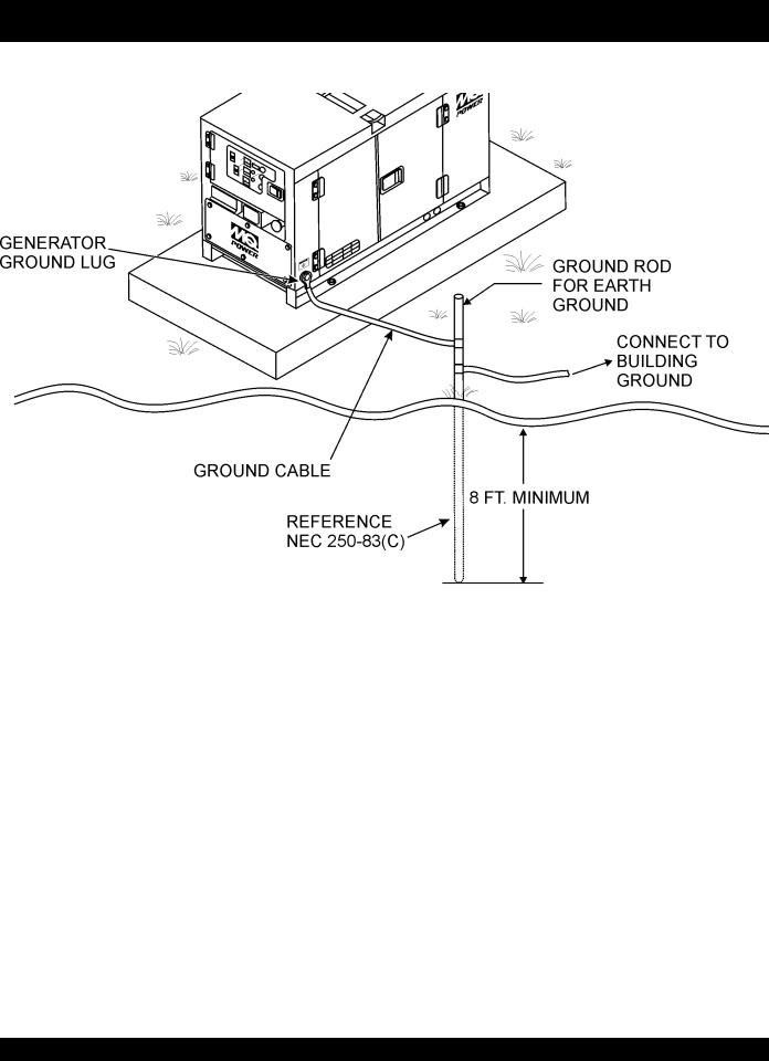
Figure 2. Typical Generator Grounding Application
PAGE 16 — DCA10SPX4/DCA10SPXU4 — OPERATION AND PARTS MANUAL — REV. #0 (08/05/09)
DCA10SPX4/DCA10SPXU4 — INSTALLATION
Outdoor Installation
Install the generator in a area that is free of debris, bystanders, and overhead obstructions. Make sure the generator is on secure level ground so that it cannot slide or shift around. Also install the generator in a manner so that the exhaust will not be discharged in the direction of nearby homes.
The installation site must be relatively free from moisture and dust. All electrical equipment should be protected from excessive moisture. Failure to do will result in deterioration of the insulation and will result in short circuits and grounding.
Foreign materials such as dust, sand, lint and abrasive materials have a tendency to cause excessive wear to engine and alternator parts.
CAUTION - EXHAUST HAZARD
Pay close attention to ventilation when operating the generator inside tunnels and caves. The engine exhaust contains noxious elements.Engine exhaust must be routed to a ventilated area.
Indoor Installation
Exhaust gases from diesel engines are extremely poisonous.
Whenever an engine is installed indoors the exhaust fumes must be vented to the outside.The engine should be installed at least two feet from any outside wall. Using an exhaust pipe which is too long or too small can cause excessive back pressure which will cause the engine to heat excessively and possibly burn the valves.
Mounting
The generator must be mounted on a solid foundation (such as concrete) and set firmly on the foundation to isolate vibration of the generator when it is running. The generator must set at least 6 inches above the floor or grade level (in accordance to NFPA 110, Chapter 5-4.1). DO NOT remove the metal skids on the bottom of the generator. They are to resist damage to the bottom of the generator and to maintain alignment.
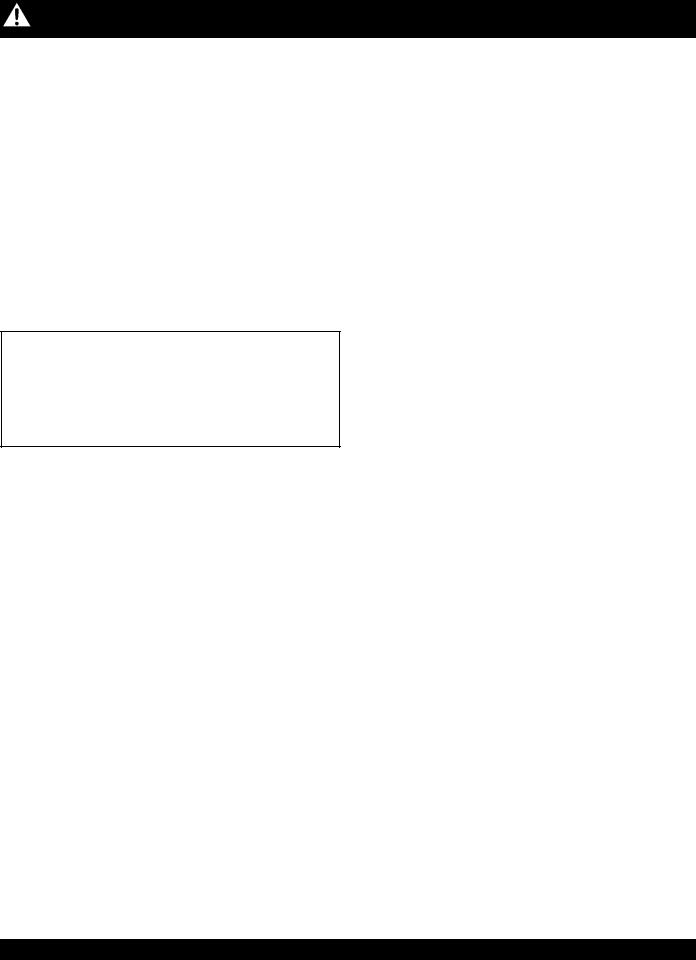
Generator Grounding
To guard against electrical shock and possible damage to the equipment, it is important to provide a good EARTH ground.
Article 250 (Grounding) of the National Electrical Code
(NEC) provides guide lines for proper grounding and specifies that the cable ground shall be connected to the grounding system of the building as close to the point of cable entry as practical.
NEC articles 250-64(b) and 250-66 set the following grounding requirements:
1.Use one of the following wire types to connect the generator to earth ground.
a.Copper - 10 AWG (5.3 mm2) or larger.
b.Aluminum - 8 AWG (8.4 mm2) or larger.
2.When grounding the generator (Figure 2) connect the ground cable between the lock washer and the nut on the generator and tighten the nut fully.Connect the other end of the ground cable to earth ground.
3.NEC article 250-52(c) specifies that the earth ground rod should be buried aminimum of 8 ft.into the ground.
When connecting the generator NOTE to any buildings electrical system ALWAYS consult with
a licensed electrician.
DCA10SPX4/DCA10SPXU4 — OPERATION AND PARTS MANUAL — REV. #0 (08/05/09) — PAGE 17

DCA10SPX4/DCA10SPXU4 — GENERAL INFORMATION
DCA-10SPX4 Whisperwatt™ Series Familiarization
Generator
The MQ Power Model DCA10SPX4 is a 8 kW generator
(Figure 3) that is designed as a high quality portable (requires a trailer for transport) power source for telecom sites, lighting facilities, power tools, submersible pumps and other industrial and construction machinery.
Generator Control Panel
The “Engine Operating Panel” is provided with the following:
■Warning Lamp Unit
■Speed Control Switch
■Frequency Meter (Hz)
■AC Ammeter (Amps)
■AC Voltmeter (Volts)
■Voltage Regulator
■Ignition Switch
■Hour Meter
■3-Pole, 45 amp Main Circuit Breaker
■1-Pole, 20 amp Circuit Breaker (for GFCI)
■1-Pole, 30 amp Circuit Breaker (for L5-30R)
■1-Pole, 30 amp Circuit Breaker (for L6-30R)
■1-Pole, 45 amp Circuit Breaker (for CS6369)
■“Control Box” (located behind the Gen. Control Panel)
■Automatic Voltage Regulator
■Current Transformer
■Voltage Rectifer
■Starter Relay
Output Terminal Panel
The “Output Terminal Panel” is provided with the following:
■100V output receptacle (5-20R) GFCI, 20A
■100V output receptacle (L5-30R), 30A
■200V output receptacle(L6-30R), 30A
■100/200V output receptacle (CS6369), 45A
Open Delta Excitation System
The generator is equipped with the state of the art "OpenDelta" excitation system. The open delta system consist of an electrically independent winding wound among stationary windings of the AC output section.
There are four connections of the open delta A, B, C and D. During steady state loads, the power from the voltage regulator is supplied from the parallel connections of A to B,
A to D, and C to D. These three phases of the voltage input to the voltage regulator are then rectified and are the excitation current for the exciter section.
When a heavy load, such as a motor starting or a short circuit occurs, the automatic voltage regulator (AVR) switches the configuration of the open delta to the series connection of B to C. This has the effect of adding the voltages of each phase to provide higher excitation to the exciter section and thus better voltage response during the application of heavy loads.
The connections of the AVR to the AC output windings are for sensing only. No power is required from these windings.
The open-delta design provides virtually unlimited excitation current, offering maximum motor starting capabilities. The excitation does not have a "fixed ceiling" and responds according the demands of the required load.
Engine
The DCA-10SPX4 is powered by a 3 cylinder, water cooled,
Kubota Model D1503-M diesel engine. This engine is designed to meet every performance requirement for the generator. Reference Table 2 for engine specifications.
In keeping with MQ Power's policy of constantly improving its products, the specifications quoted herein are subject to change without prior notice.
Electric Governor System
The electric governor system controls the RPMs of the engine. When the engine demand increases or decreases, the governor system regulates the frequency variation to ±.25%.
Extension Cables
When electric power is to be provided to various tools or loads at some distance from the generator, extension cords are normally used. Cables should be sized to allow for distance in length and amperage so that the voltage drop between the generator and point of use (load) is held to a minimum. Use the cable selection chart (Table 6) as a guide for selecting proper extension cable size.
PAGE 18 — DCA10SPX4/DCA10SPXU4 — OPERATION AND PARTS MANUAL — REV. #0 (08/05/09)

DCA10SPX4/DCA10SPXU4 — MAJOR COMPONENTS
|
Table 4. Generator Major Components |
||
|
|||
|
|
|
|
|
ITEM NO. |
DESCRIPTION |
|
|
|
|
|
|
1 |
Fuel Tank Assembly |
|
|
|
|
|
|
2 |
Engine and Radiator Assembly |
|
|
|
|
|
|
3 |
Muffler Assembly |
|
Figure 3. Major Components |
|
|
|
4 |
Generator Assembly |
||
|
|||
|
|
|
|
|
5 |
Battery Assembly |
|
|
|
|
|
|
6 |
Generator Control Panel Assembly |
|
|
|
|
|
|
7 |
Output Receptacles Assembly |
|
|
|
|
|
|
8 |
Ground Terminal Assembly |
|
|
|
|
|
DCA10SPX4/DCA10SPXU4 — OPERATION AND PARTS MANUAL — REV. #0 (08/05/09) — PAGE 19

DCA10SPX4/DCA10SPXU4 — GENERATOR CONTROL PANEL
The definitions below describe the controls and functions of the Generator Control Panel (Figure 4).
1.Frequency Meter – Indicates the output frequency in hertz (Hz). Normally 50 Hz.
2.AC Ammeter – Indicates the amount of current the load is drawing from the generator.
3.AC Voltmeter – Indicates output voltage.
4.Engine Warning Display Module – This module displays the following engine failures:
A.Overheat Lamp – This lamp goes ON when the coolant is over 234oF. If the lamp goes ON during normal operation of the generator, the emergency shut-down device will stop the engine automatically.
B.Low Oil Pressure Lamp – During normal operation of the generator this lamp should remain OFF. After the oil pressure rises after start-up,
the lamp will go OFF. This lamp goes ON when the oil presure drops below 7.1 PSI.If this lamp is ever lit (ON) during normal operation of the generator, the emergency shut-down device will stop the engine automatically.
C.Low Battery Fluid Lamp – This lamp goes ON when the battery fluid is low. If this lamp goes ON during normal operation of the generator, stop the engine and fill the battery with distilled water to the specified level.
D.Pre-Heat Lamp – This lamp indicates when the engine is ready for starting during cold weather operating condition.
When engine failures (this light flashes) occur, refer to the
TROUBLESHOOTIG for a more detailed code.
5.Hour Meter – Indicates the number of hours machine has been in use.
6.Speed Control Switch –This switch controls the speed of the engine (idle/high).
Figure 4. Generator Control Panel
7.Ignition Switch – Insert ignition key into this switch to start engine.
8.Voltage Regulator Control – Allows ±15% manual adjustment of the generator’s output voltage.
9.Twist Lock Dual Voltage Receptacle (CS6369) –
Provides 100/200 VAC output (45 amps max).
10.Auxillary Receptacle (for L6-30R) – Provides 200VAC output (30 amps max).
11.Auxillary Receptacle (for L5-30R) – Provides 100VAC output (30 amps max).
12.GFCI Receptacle – Provides 100VAC output (20 amps max).
13.CS6369 Receptacle Circuit Breaker -This single-pole,
45A breaker is provided to protect the CS6369 receptacle from overload.
14.Ground Terminal - Ground Terminal for Output Receptacles.
15.Auxillary Receptacle Circuit Breaker - This singlepole, 30A breaker is provided to protect the auxillary receptacle (for L6-30R) from overload.
16.Auxillary Receptacle Circuit Breaker - This singlepole, 30A breaker is provided to protect the auxillary receptacle (for L5-30R) from overload.
17.GFCI Receptacle Circuit Breaker - This single-pole,
20A GFCI breaker is provided to protect the GFCI receptacle from overload.
18.Main Circuit Breaker – This three-pole, 45A main breaker is provided to protect the the generator from overload.
PAGE 20 — DCA10SPX4/DCA10SPXU4 — OPERATION AND PARTS MANUAL — REV. #0 (08/05/09)
DCA-10SPX4 /U4— OUTPUT TERMINAL PANEL FAMILIARIZATION
Output Terminal Panel
The Output Terminal Panel (Figure 5) shown below is located on the right-hand side (left from control panel) of the generator. Lift up on the cover to gain access to receptacles and terminal lugs.
Output Terminal Familiarization
The “Output Terminal Panel ” (Figure 5) is provided with the following:
■100V GFCI receptacle @ 20 amp
■100V receptacle @ 30 amp
■200V receptacle @ 30 amp
■100/200V CS6369 receptacle @ 45 amp
■Ground
Figure 5. Output Terminal Panel
DCA10SPX4/DCA10SPXU4 — OPERATION AND PARTS MANUAL — REV. #0 (08/05/09) — PAGE 21

DCA-10SPX4 /U4 — OUTPUT TERMINAL PANEL FAMILIARIZATION
100 VAC GFCI Receptacle
This100 VAC, 20 amp GFCI (Duplex Nema 5-20R) receptacle can be used anytime the generator is in operation. The receptacle is protected by a 20 amp circuit breaker. The breaker can be located on the generator control panel.
Pressing the reset button resets the GFCI receptacle after being tripped. Pressing the Test Button (See Figure 6) in the center of the receptacle will check the GFCI function. This receptacle should be tested at least once a month.
L5-30R Twist Lock 100 VAC Receptacle (Option)
There is one L5-30R, 100 VAC 30 amp auxilliary twist-lock receptacle (Figure 8) provided on the output terminal panel.
This receptacle is protected by a 30 amp circuit breaker.
Figure 6. G.F.C.I. Receptacle
Twist Lock DualVoltage 100/200VAC Receptacle (Option)
There is one CS-6369 100/200V, 45 amp auxilliary twistlock receptacle (Figure 7) provided on the output terminal panel. This receptacle is protected by a 45 amp circuit breaker.
Figure 8. L5-30R Twist-Lock
Auxiliary Receptacle
L6-30R Twist Lock 200 VAC Receptacle (Option)
There is one L6-30R, 200 VAC 30 amp auxilliary twist-lock receptacle (Figure 9) provided on the output terminal panel.
This receptacle is protected by a 30 amp circuit breaker.
Figure 9. L6-30R Twist-Lock
Auxiliary Receptacle
Turn the voltage regulator control knob (Figure 10) on the control panel to obtain the desired voltage. Turning the knob clockwise will increase the voltage, turning the knob counter-clockwise will decrease the voltage.
Figure 7. CS6369 Twist-Lock
Auxiliary Receptacle
Figure 10. Voltage Regulator Control Knob
PAGE 22 — DCA10SPX4/DCA10SPXU4 — OPERATION AND PARTS MANUAL — REV. #0 (08/05/09)
DCA-10SPX4 /U4— OUTPUT TERMINAL PANEL FAMILIARIZATION
Connecting Loads
Loads are connected to the generator by the convenience receptacles (Figure 11). Make sure to read the operation manual before attempting to connect a load to the generator.
To protect the output terminals from overload, a
3-pole, 45A main circuit breaker is provided. Make sure to switch ALL circuit breakers to the OFF position prior to starting the engine.
Figure 11. Connecting Loads
DCA10SPX4/DCA10SPXU4 — OPERATION AND PARTS MANUAL — REV. #0 (08/05/09) — PAGE 23
 Loading...