


DCA-70SSJU

PARTS AND OPERATION MANUAL
MULTIQUIP INC
..
..
. PARTS DEPARTMENT:
18910 WILMINGTON AVE. 800-427-1244
CARSON, CALIFORNIA 90746 FAX: 800-672-7877
310-537-3700
SERVICE DEPARTMENT:
800-421-1244 800-835-2551
FAX: 310-537-3927 FAX: 310-638-8046
E-mail:mq@multiquip.com
www:multiquip.com
OPERATION AND PARTS MANUAL
MQ POWER
DCA-70SSJU
WHISPERWATT
TM
GENERATOR
S/N 7300000-2140 KEY START
S/N 7302141-3869 ECU/EGS
PARTS LIST NO. M1870300034A
Revision #5 (06/03/03)
© COPYRIGHT 2003, MULTIQUIP INC.
PAGE 2 — DCA-70SSJU SERIES — OPERATION AND PARTS MANUAL (STD) — REV. #5 (06/03/03)
DCA-70SSJU SERIES — OPERATION AND PARTS MANUAL (STD)— REV. #5 (06/03/03) — PAGE 3
1
HERE'S HOW TO GET HELP
PLEASE HAVE THE MODEL AND SERIAL
NUMBER ON-HAND WHEN CALLING
PARTS DEPARTMENT
800-427-1244 or 310-537-3700
FAX: 800-672-7877 or 310-637-3284
SERVICE DEPARTMENT
800-421-1244
FAX: 310- 537-4259
TECHNICAL ASSISTANCE
800-478-1244
FAX: 310- 631-5032
WARRANTY DEPARTMENT
888-661-4279, or 310-661-4279
FAX: 310- 537-1173

PAGE 4 — DCA-70SSJU SERIES — OPERATION AND PARTS MANUAL (STD) — REV. #5 (06/03/03)
TABLE OF CONTENTS
COMPONENT DRACOMPONENT DRA
COMPONENT DRACOMPONENT DRA
COMPONENT DRA
WINGSWINGS
WINGSWINGS
WINGS
Name Plate And Decals ............................................ 64-65
Generator Assembly .................................................. 66-69
Control Box Assembly ............................................... 70-75
Engine & Radiator Assembly..................................... 76-79
Engine Operating Panel Assembly ............................ 80-83
Output Terminal Assembly ......................................... 84-85
Battery Assembly ...................................................... 86-87
Muffler Assembly ...................................................... 88-89
Fuel Tank Assembly .................................................. 90-95
Enclosure Assembly ................................................. 96-97
Rubber Seal Assembly .............................................. 98-99
Terms and Condition of Sale — Parts .......................... 100
Specification and part
number are subject to
change without notice.
NOTE
MQ POWER DCA70SSJUMQ POWER DCA70SSJU
MQ POWER DCA70SSJUMQ POWER DCA70SSJU
MQ POWER DCA70SSJU
AC GENERAAC GENERA
AC GENERAAC GENERA
AC GENERA
TORTOR
TORTOR
TOR
Here's How To Get Help ....................................................3
Table Of Contents ............................................................. 4
Parts Ordering Procedures ............................................... 5
Specifications ................................................................... 6
Dimensions (Top, Side, Front) ........................................... 7
Safety Message Alert Symbols .................................... 8-9
Rules for Safe Operation ........................................... 10-13
Installation ................................................................. 14-15
Towing Safety Precaution ...............................................16
Trailer Specifications ................................................. 17-19
Generator Decals....................................................... 20-21
General Information ........................................................ 22
Major Components .........................................................23
Generator Control Panel ................................................. 24
Engine Operating Panel (up to S/N 73002140) ............... 25
Engine Operating Panel (S/N 73002140~) ................. 26-27
Output Terminal Panel Familiarization ........................ 28-30
Load Application ............................................................. 31
Generator Outputs ..................................................... 32-33
Gauge Reading ............................................................... 33
Output Terminal Panel Connections ........................... 34-35
Pre Setup .................................................................. 36-40
Generator Start-up Procedure (Manual) ..................... 41-44
Generator Start-up Procedure (Auto Mode) .................... 45
Generator Shut-Down Procedure .................................... 46
Maintenance .............................................................. 47-49
Trailer Brakes Maintenance ............................................ 50
Trailer Maintenance .................................................... 51-52
Trailer Wiring Diagram ..................................................... 53
Generator Wiring Diagram ............................................... 54
Engine Wiring Diagram (w/ Controller) ............................ 55
Engine Wiring Diagram (Ignition Switch) ......................... 56
Engine Troubleshooting .............................................. 57-58
Generator Troubleshooting .............................................. 59
Engine Controller Troubleshooting ................................... 60
Explanation of Code in Remarks Column ....................... 62
Suggested Spare Parts .................................................. 63
DCA-70SSJU SERIES — OPERATION AND PARTS MANUAL (STD)— REV. #5 (06/03/03) — PAGE 5
1
PARTS ORDERING PROCEDURES
When ordering parts,
please supply the following information:
❒❒
❒❒
❒ Dealer account number
❒❒
❒❒
❒ Dealer name and address
❒❒
❒❒
❒ Shipping address (if different than billing address)
❒❒
❒❒
❒ Return fax number
❒❒
❒❒
❒ Applicable model number
❒❒
❒❒
❒ Quantity, part number and description of each part
❒❒
❒❒
❒ Specify preferred method of shipment:
✓ FedEx or UPS Ground
✓ FedEx or UPS Second Day or Third Day
✓ FedEx or UPS Next Day
✓ Federal Express Priority One
✓ DHL
✓ Tr u ck
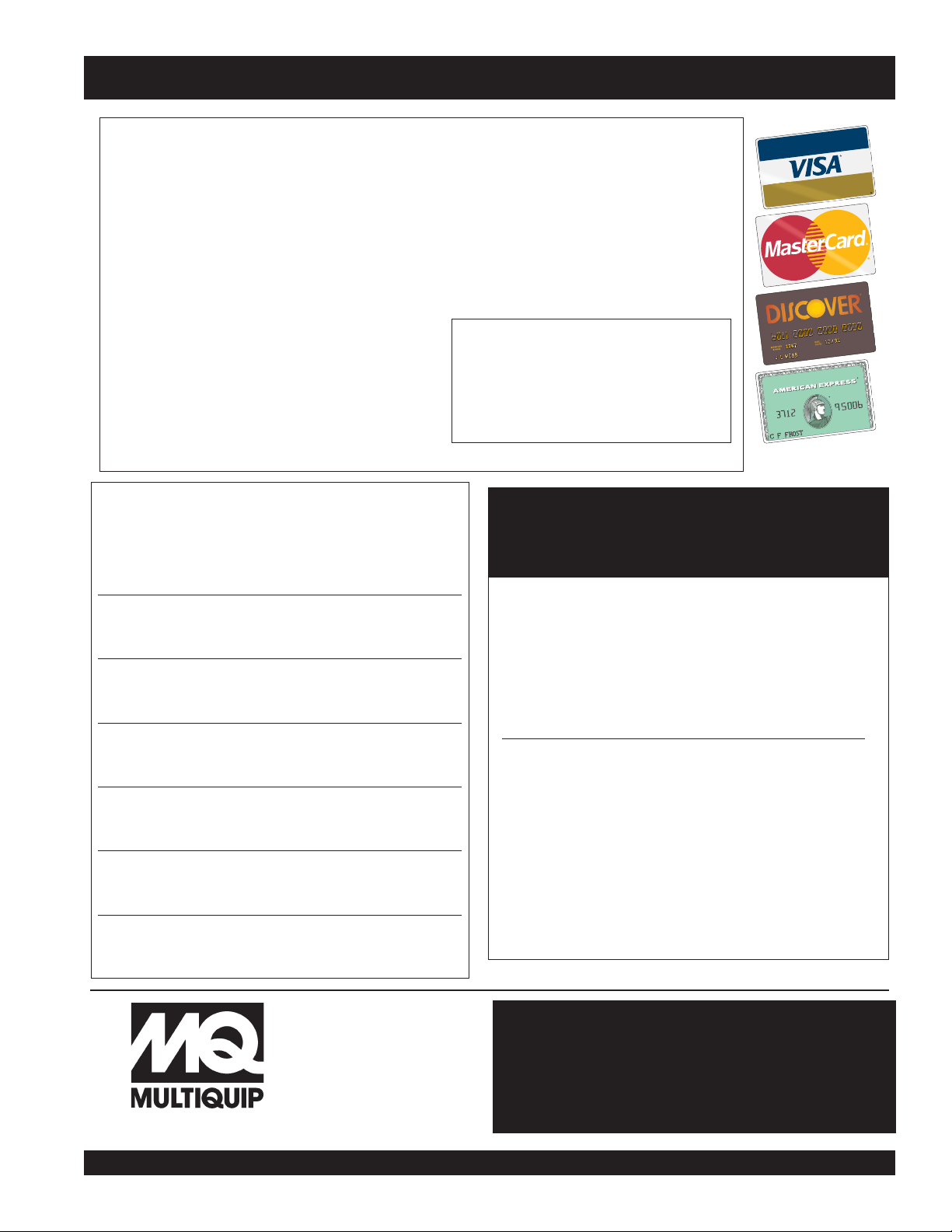
Here’s how to get help...
Please have the model and serial number on
hand when calling.
Parts Department
800-427-1244 Fax: 800-672-7877
310-537-3700 Fax: 310-637-3284
Mayco Parts
800-306-2926 Fax: 800-672-7877
310-537-3700 Fax: 310-637-3284
Service Department
800-478-1244 Fax: 310-537-4259
310-537-3700
MQ Power Service Department
800-835-2551 Fax: 310-638-8046
310-537-3700
Warranty Department
800-421-1244, Ext. 279 Fax: 310-537-1173
310-537-3700, Ext. 279
Multiquip’s Main Phone Numbers
800-421-1244 Fax: 310-537-3927
310-537-3700
Note: Unless otherwise indicated by customer, all
orders are treated as “Standard Orders”, and will
ship within 24 hours. We will make every effort to
ship “Air Shipments” the same day that the order is
received, if prior to 2PM west coast time. “Stock
Orders” must be so noted on fax or web forms.
Extra Discounts!
All parts orders which include complete part numbers
and are received by our automated web parts order
system, or by fax qualify for the following extra
discounts:
Ordered Standard Stock orders
via orders ($750 list and above)
Fax 3% 10%
Web 5% 10%
Special freight allowances
when you order 10 or more
line items via Web or Fax!**
FedEx Ground Service
at no charge for freight
No other allowances on freight shipped by any other
carrier.
Place Your Parts Order Via Web or Fax
For Even More Savings!
NOTE: DISCOUNTS ARE SUBJECT TO CHANGE
MULTIQUIP INC.
18910 WILMINGTON AVENUE
POST OFFICE BOX 6254
CARSON, CALIFORNIA 90749
310-537-3700 • 800-421-1244
FAX: 310-537-3927
E-MAIL: mq@multiquip.com
WWW: multiquip.com
Direct TOLL-FREE access
to our Parts Department:
Toll-free nationwide — 800-427-1244
PAGE 6 — DCA-70SSJU SERIES — OPERATION AND PARTS MANUAL (STD) — REV. #5 (06/03/03)
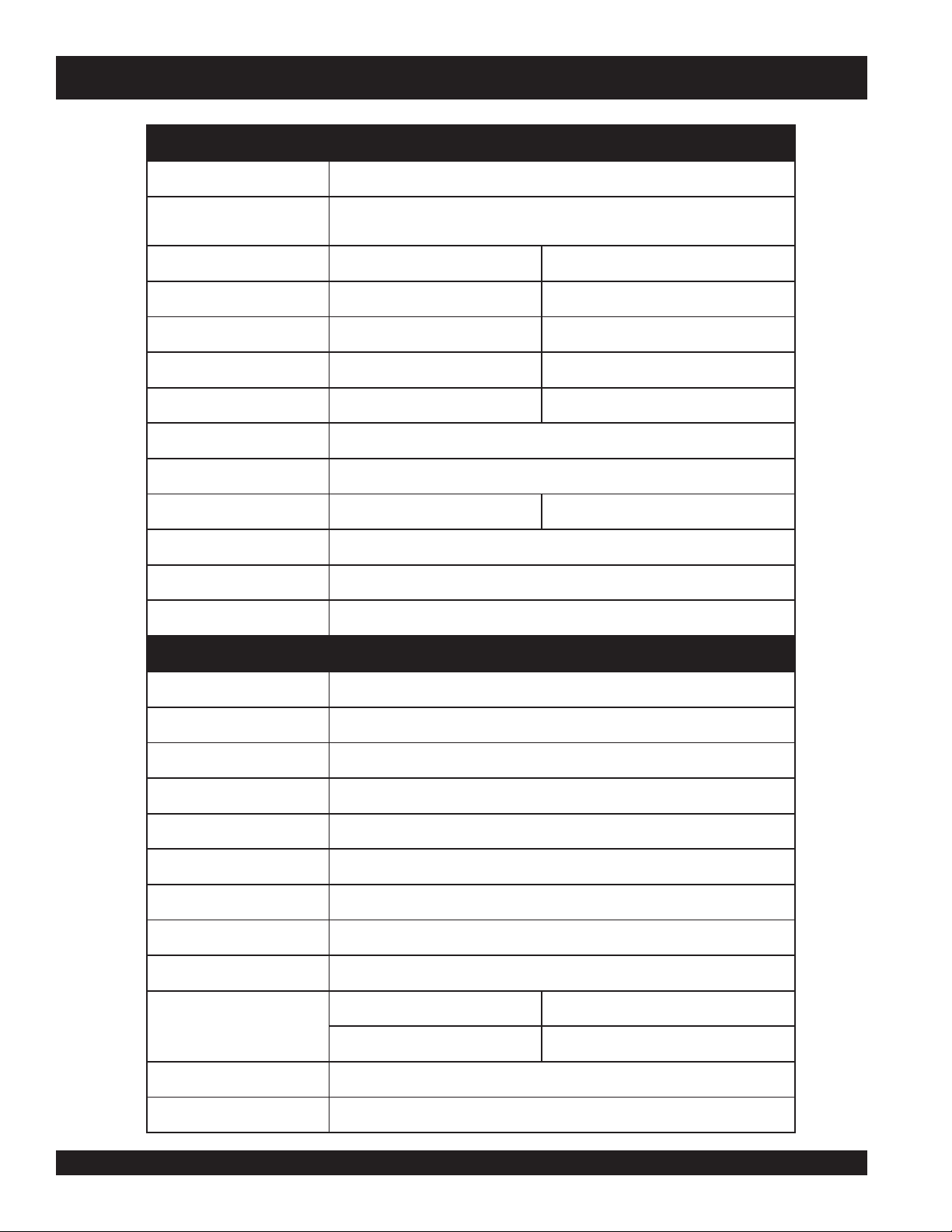
DCA-70SSJU SERIES — SPECIFICATIONS
snoitacificepSrotareneG.1elbaT
ledoMUJSS07-ACD
epyT
suonorhcnysepytdetcetorpnepo,detalitnevfles,dleifgnivloveR
rotareneg
noitcennoCerutam
rAlartueNhtiwratSgaZgiZ
esahP
3elgniS
tuptuOybdnatS
)WK6.16(AVK77WK44
tuptuOemirP
)WK65(AVK07WK04
egatloV
V084roV0
42V021/042
ycneuqerF
zH06
deepS
mpr0081
rotcaFrewoP
8.01
rewoPCA.xuA
zH06,esahPelgniS
egatloV
V021
tuptuO
)2xWK4.2(
WK8.4
snoitacificepSenignE
ledoM
051FT5404EREEDNHOJ
epyT
degrahc-obrut,noitcejnitcerid,delooc-retaw,elcyC4
srednilyCfo.oN
srednilyc4
e
kortSxeroB
)mm721xmm601(.ni5x.ni91.4
tuptuOdetaR
mpr0081/PH09
tnemecalpsiD
)cc0054(.ni.uc472
gnitratS
cirtce
lE
yticapaCtnalooC
)sretil62(.lag9.6
yticapaCliOebuL
)sretil31(.lag4.3
noitpmusnoCleuF
tarh/)L9.71(.lag7.4 d
aollluf tarh/)L3.31(.lag5.3 daol4/3
tarh/)L9.9(.lag6.2 daol2/1 tarh/)L1.6(.lag6.1 daol4/1
yrettaB
HA021-V21
le
uF
leuFleseiD2#
DCA-70SSJU SERIES — OPERATION AND PARTS MANUAL (STD)— REV. #5 (06/03/03) — PAGE 7
1
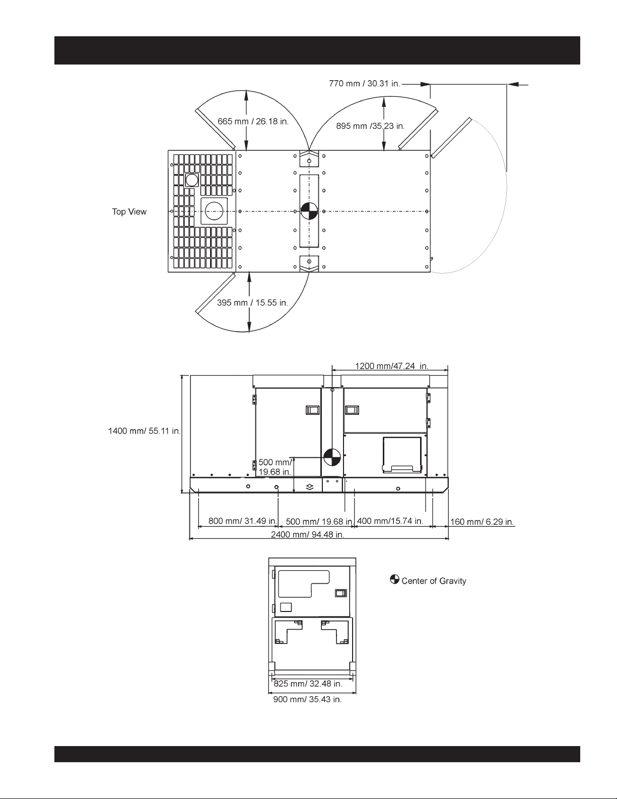
DCA-70SSJU SERIES — DIMENSIONS (TOP, SIDE AND FRONT)
Figure 1. Dimensions
PAGE 8 — DCA-70SSJU SERIES — OPERATION AND PARTS MANUAL (STD) — REV. #5 (06/03/03)
This Owner's Manual has been
developed to provide complete
instructions for the safe and
efficient operation of the MQ Power
Model DCA70SSJU Series
WHISPERWATT™ GENERATOR.
Before using this GENERATOR, ensure that the operating
individual has read and understands all instructions in this
manual.
Safety precautions should be followed at all times when operating
this equipment. Failure to read and understand the Safety
Messages and Operating Instructions could result in injury to
yourself and others.
FOR YOUR SAFETY AND THE SAFETY OF OTHERS!
SAFETY MESSAGE ALERT SYMBOLS
The three (3) Safety Messages shown below will inform you
about potential hazards that could injure you or others. The
Safety Messages specifically address the level of exposure to
the operator, and are preceded by one of three words: DANGER,
WARNING, or CAUTION.
DANGER: You WILL be KILLED or
SERIOUSLY injured if you DO NOT follow
directions.
WARNING: You CAN be KILLED or
SERIOUSLY injured if you DO NOT follow
directions.
CAUTION: You CAN be injured if you
DO NOT follow directions.
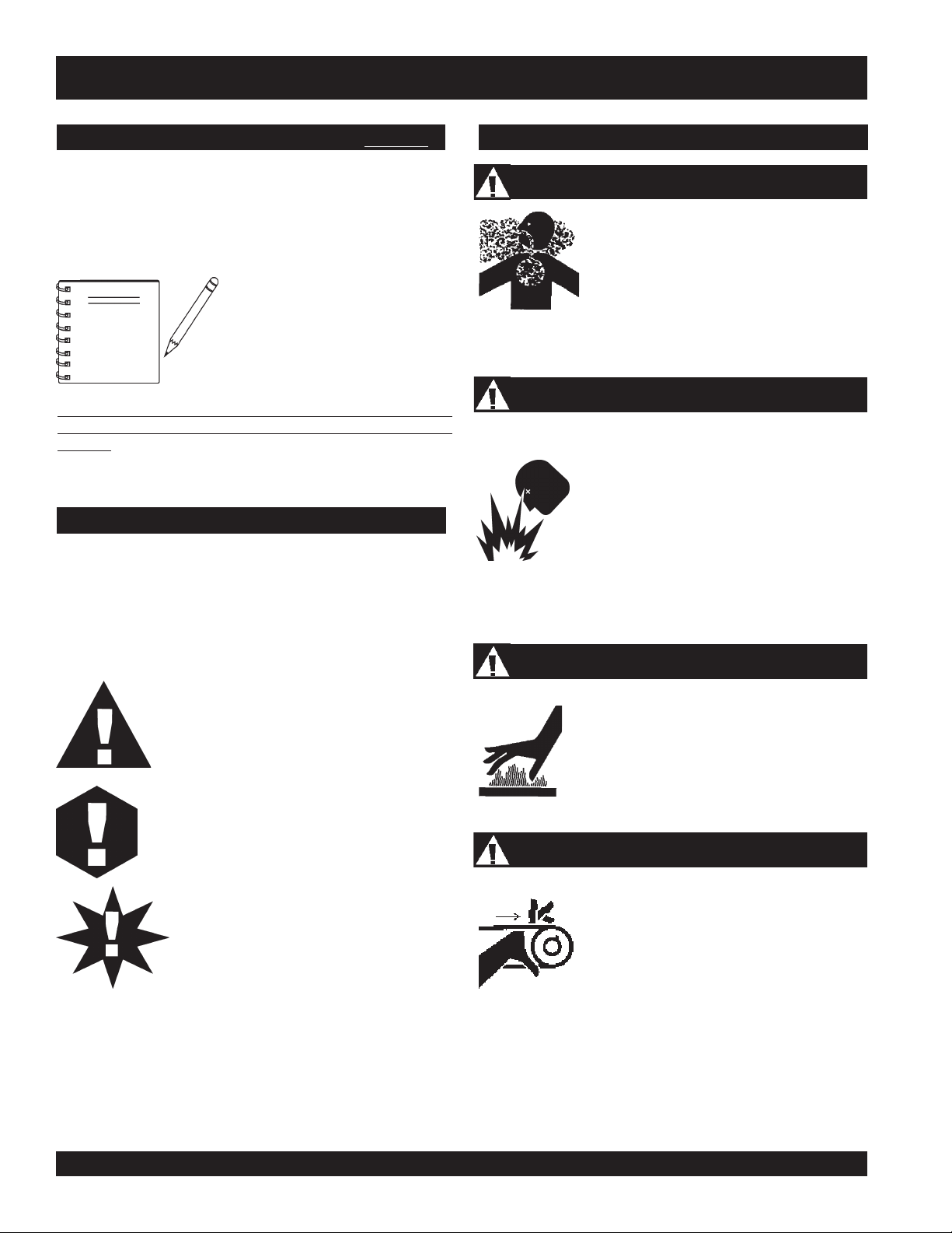
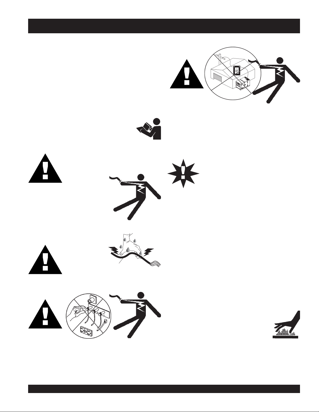
HAZARD SYMBOLS
Engine exhaust gases contain poisonous
carbon monoxide. This gas is colorless and
odorless, and can cause death if inhaled.
NEVER operate this equipment in a confined
area or enclosed structure that does not
provide ample free flow air.
Potential hazards associated with trowel operation will be
referenced with "
Hazard Symbols
" which appear throughout
this manual, and will be referenced in conjunction with Safety
"
Message Alert Symbols
".
Diesel fuel is extremely flammable, and its
vapors can cause an explosion if ignited. DO
NOT start the engine near spilled fuel or
combustible fluids. DO NOT fill the fuel tank
while the engine is running or hot. DO NOT
overfill tank, since spilled fuel could ignite if it
comes into contact with hot engine parts or
sparks from the ignition system. Store fuel in
approved containers, in well-ventilated areas
and away from sparks and flames. NEVER
use fuel as a cleaning agent.
Burn Hazards
Engine components can generate extreme heat.
To prevent burns, DO NOT touch these areas
while the engine is running or immediately after
operations. NEVER operate the engine with
heat shields or heat guards removed.
Rotating Parts
NEVER operate equipment with covers, or
guards removed. Keep
fingers
,
hands
,
hair
and
clothing
away from all moving parts to
prevent injury.
Explosive Fuel
Lethal Exhaust Gases
NOTE
DCA70SSJU — SAFETY MESSAGE ALERT SYMBOLS
DCA-70SSJU SERIES — OPERATION AND PARTS MANUAL (STD)— REV. #5 (06/03/03) — PAGE 9
1
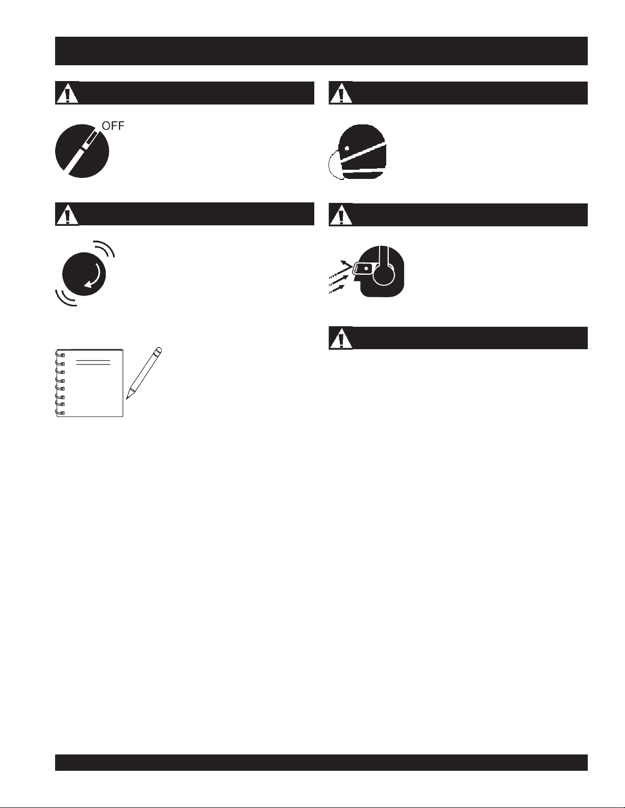
Accidental Starting
ALWAYS place the engine ON/OFF switch
in the OFF position, when the trowel is not
in use.
Over Speed Conditions
NEVER tamper with the factory settings of the
engine governor or settings. Personal injury
and damage to the engine or equipment can
result if operating in speed ranges above
maximum allowable.
Respiratory Hazard
ALWAYS wear approved respiratory protection.
ALWAYS wear approved eye and hearing
protection.
Sight and Hearing hazard
Equipment Damage Messages
Other important messages are provided throughout this manual
to help prevent damage to your trowel, other property, or the
surrounding environment.
This
generator
, other property, or
the surrounding environment could
be damaged if you do not follow
instructions.
NOTE
DCA70SSJU — SAFETY MESSAGE ALERT SYMBOLS
PAGE 10 — DCA-70SSJU SERIES — OPERATION AND PARTS MANUAL (STD) — REV. #5 (06/03/03)
DCA-70SSJU SERIES — RULES FOR SAFE OPERATION
CAUTIONCAUTION
CAUTIONCAUTION
CAUTION
:
Failure to follow instructions in this manual may
lead to serious injury or even death! This
equipment is to be operated by trained and
qualified personnel only! This equipment is for
industrial use only.
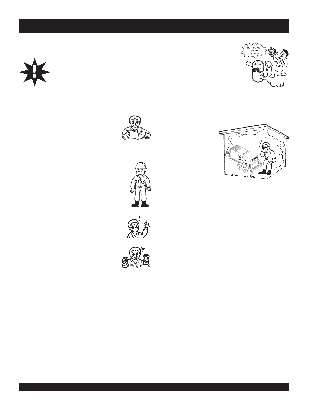
The following safety guidelines should always be used when
operating the DCA-70SSJU Series Generator:
GENERAL SAFETY
■
DO NOT operate or service this equipment
before reading this entire manual.
■
This equipment should not be operated by persons under 18
years of age.
■
NEVER operate this equipment without proper
protective clothing, shatterproof glasses, steel-
toed boots and other protective devices required
by the job.
■
NEVER operate this equipment when not feeling
well due to fatigue, illness or taking medicine.
■
NEVER operate this equipment under the
influence or drugs or alcohol.
■
NEVER use accessories or attachments, which are not
recommended by MQ Power for this equipment. Damage to
the equipment and/or injury to user may result.
■
Manufacture does not assume responsibility for any accident
due to equipment modifications.
■
Whenever necessary, replace nameplate, operation and
safety decals when they become difficult read.
■
ALWAYS check the machine for loosened threads or bolts
before starting.
■
NEVER operate the generator in an explosive atmosphere or
near combustible materials. An explosion or fire could result
causing severe
bodily harm or even death.
■
High Temperatures – Allow the engine to cool before
performing service and maintenance functions. Contact
with
hot!
components can cause serious burns.
■
The engine of this
generator requires an
adequate free flow of
cooling air.
NEVER
operate the generator
in any enclosed or
narrow area where free
flow of the air is
restricted. If the air flow
is restricted it will
cause serious damage to the generator or engine and
may cause injury to people. The generator engine gives
off DEADLY carbon monoxide gas.
■
ALWAYS make sure generator is properly grounded.
■
NEVER use gas piping as an electrical ground.
■
DO NOT place hands or fingers inside generator engine
compartment when engine is running.
■
ALWAYS make sure generator installation is accordance with
national and local electrical codes
.
■
ALWAYS have a qualified electrician perform the generator
wiring installation.
■
NEVER power cables or cords
lay in wate
r.
■
NEVER
stand in water
while AC power from the generator
is being transfer to a load.
■
NEVER use a defective or frayed power cable. Check the
cable for cuts in the insulation.
■
NEVER use a extension cord that is frayed or damaged where
the insulation has been cut.
■
ALWAYS make certain that proper extension cord has been
selected for the job See Table 5.
■
The electrical voltage required to operate the generator can
cause severe injury or even death through physical contact
with live circuits.
Turn all circuit breakers OFF before
performing maintenance on the generator.
■
NEVER touch the hot exhaust
manifold, muffler or cylinder. Allow
these parts to cool before servicing
engine or generator.
DCA-70SSJU SERIES — OPERATION AND PARTS MANUAL (STD)— REV. #5 (06/03/03) — PAGE 11
1
DCA-70SSJU SERIES — RULES FOR SAFE OPERATION
■
Backfeed to a utility system can cause
electrocution
and or
property damage. DO NOT connect to any building's electrical
system except through an approved device or after building
main switch is opened. ALWAYS have a licensed electrician
perform the installation
CAUTIONCAUTION
CAUTIONCAUTION
CAUTION
:
DO NOT touch or open any of the below
mentioned components while the
generator is running. Always allow
sufficient time for the engine and generator
to cool before performing maintenance.
Radiator
1. Radiator Cap - Removing the radiator cap while the engine
is hot will result in high pressurized, boiling water to gush
out of the radiator, causing severe scalding to any persons
in the general area of the generator.
2. Coolant Drain Plug - Removing the coolant drain plug
while the engine is hot will result in hot coolant to gush out
of the coolant drain plug, therefore causing severe scalding
to any persons in the general area of the generator.
3. Engine Oil Drain Plug - Removing the engine oil drain
plug while the engine is hot will result in hot oil to gush out
of the oil drain plug, therefore causing severe scalding to
any persons in the general area of the generator.
DANGERDANGER
DANGERDANGER
DANGER
:
DANGERDANGER
DANGERDANGER
DANGER
:
■
NEVER touch output terminals during operation. This is
extremely dangerous. ALWAYS stop the machine and
place the circuit breaker in the “OFF” position when contact
with the output terminals is required. There exists the
possibility of
electrocution, electrical shock or burn,
which can cause severe bodily harm or even death
!
Never use damaged or worn cables when
connecting equipment to the generator.
Make sure power
connecting
cables are
securely connected to the
generator’s output terminals,
insufficient tightening of the
terminal connections may cause
damage to the generator and
electrical shock.
.
Maintenance Safety
■
NEVER lubricate components or attempt service on a running
machine.
■
ALWAYS allow the machine a proper
amount of time to cool before servicing.
■
Keep the machinery in proper running condition.
■
Fix damage to the machine immediately and always replace
broken parts.
■
ALWAYS make sure that electrical circuits are properly
grounded
per the
National Electrical Code
(NEC) and local
codes before operating generator. Severe
injury
or
death!
by
electrocution can result from operating an ungrounded
generator.
■
ALWAYS be sure the operator is familiar with proper safety
precautions and operations techniques before using generator.
■
ALWAYS store equipment properly when it is not being used.
Equipment should be stored in a clean, dry location out of the
reach of children.
■
ALWAYS read, understand, and follow
procedures in Operator’s Manual before
attempting to operate equipment.
DANGERDANGER
DANGERDANGER
DANGER
:
DANGERDANGER
DANGERDANGER
DANGER
:
POWER
CORD
(POWER ON)
WET
HANDS
NEVER grab or
touch a live
power cord with
wet hands , the
possibility exists
of electrical shock, electrocution, and even
death!
PAGE 12 — DCA-70SSJU SERIES — OPERATION AND PARTS MANUAL (STD) — REV. #5 (06/03/03)
DCA-70SSJU— RULES FOR SAFE OPERATION
■
NEVER Run engine without air filter. Severe engine
damage may occur.
■
ALWAYSservice air cleaner frequently to prevent engine
malfunction.
■
ALWAYS disconnect the
negative battery terminal
before
performing service on the generator.
■
ALWAYS be sure the operator is familiar with proper safety
precautions when operating the generator set.
■
ALWAYS store equipment properly when not in use.
■
DO NOT leave the generator running in the
manual mode
unattended.
■
DO NOT allow unauthorized people to operate this
equipment.
■
ALWAYS read, understand, and follow procedures in
Operator’s Manual before attempting to operate equipment.
■
Refer to the
John Deere Engine Owner's Manual
for
engine technical questions or information.
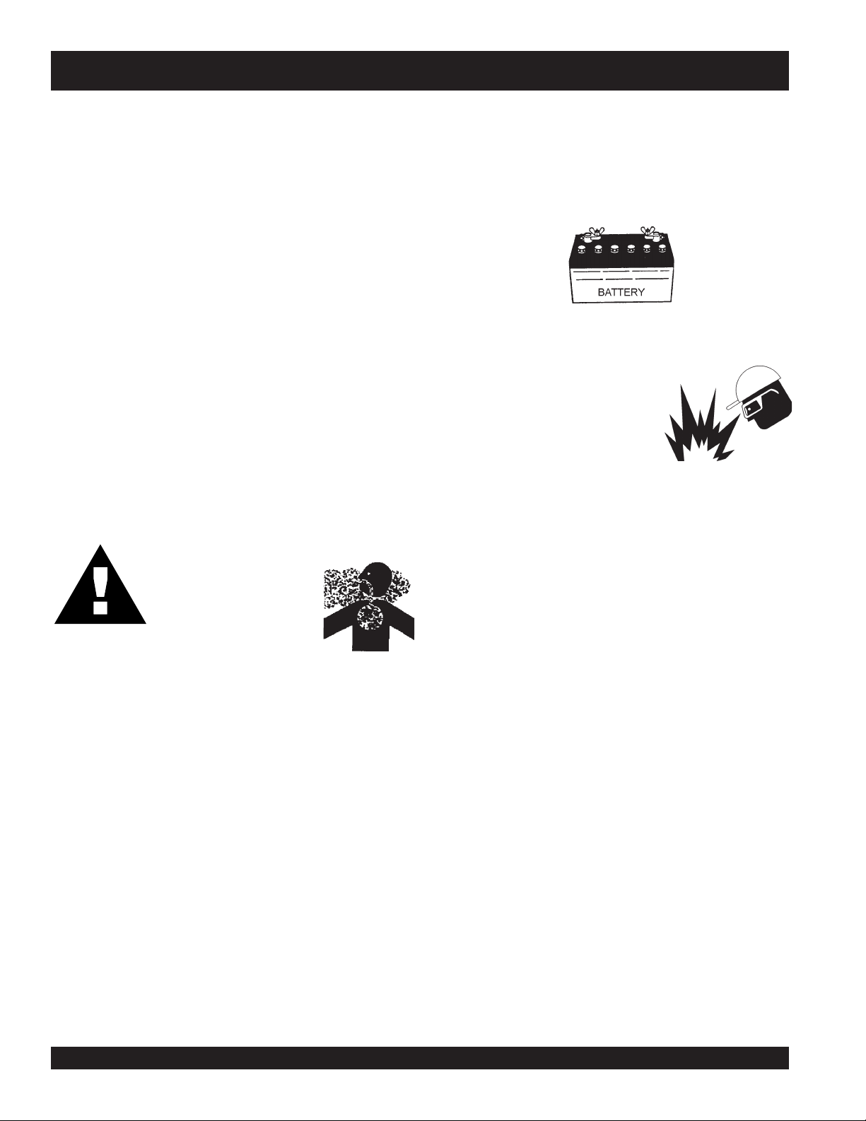
Battery
The battery contains acids that can cause injury to the eyes
and skin. To avoid eye irritation,
always
wear safety glasses.
Use well insulated gloves when picking up the battery. Use
the following guidelines when handling the battery:
1. DO NOT drop the battery. There is the possibility of risk
that the battery may explode.
2. DO NOT expose the battery to
open flames, sparks, cigarettes
etc. The battery contains
combustible gases and liquids. If
these gases and liquids come in
contact with a flame or spark, an
explosion could occur.
3. ALWAYS keep the battery charged. If the battery is not
charged a buildup of combustible gas will occur.
4. ALWAYS keep battery charging and cables in good working
condition. Repair or replace all worn cables.
5. ALWAYS recharge the battery in an vented air
environment, to avoid risk of a dangerous concentration
of combustible gases.
6. In case the battery liquid (dilute sulfuric acid) comes in
contact with
clothing or skin
, rinse skin or clothing
immediately with plenty of water.
7. In case the battery liquid (dilute sulfuric acid) comes in
contact with your eyes, rinse eyes immediately with plenty
of water, then contact the nearest doctor or hospital, and
seek medical attention.
Pay close attention to
ventilation when operating
the generator inside
tunnels and caves. The
engine exhaust contains noxious elements.
Engine exhaust must be routed to a
ventilated area.
DANGER:DANGER:
DANGER:DANGER:
DANGER:
Generator Grounding
To guard against electrical shock and possible damage to
the equipment, it is important to provide a good EARTH
ground.
Article 250 (Grounding) of the
National Electrical Code
(NEC) provides guide lines for proper grounding and specifies
that the cable ground shall be connected to the grounding
system of the building as close to the point of cable entry
as practical.
ALWAYS be sure to use the ground terminal (green wire)
when connecting a load to the UVWO output terminals.
Transporting
■
ALWAYS shutdown engine before transporting.
■
Tighten both fuel tank caps securely.
■
If generator is mounted on a trailer, make sure trailer
complies with all local and state safety transportation
laws. See next page “
Towing Safety Precautions
” for
basic towing techniques.
DCA-70SSJU SERIES — OPERATION AND PARTS MANUAL (STD)— REV. #5 (06/03/03) — PAGE 13
1
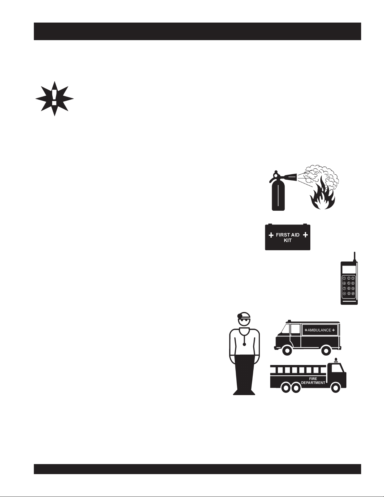
Emergencies
■
ALWAYS know the location of the nearest
fire extinguisher
.
■
ALWAYS know the location of the nearest and
first aid kit
.
■
In emergencies
always
know the location of the
nearest phone or
keep a phone on the job site
.
Also know the phone numbers of the nearest
ambulance
,
doctor
and
fire department
. This
information will be invaluable in the case of an
emergency.
To reduce the possibility of an accident while transporting
the generator on public roads, always make sure the trailer
that supports the generator and the towing vehicle are in
good operating condition and both units are mechanically
sound.
The following list of suggestions should be used when towing
your generator:
■
Make sure the hitch and coupling of the towing vehicle
are rated equal to, or greater than the trailer "gross vehicle
weight rating" (GVWR) of 6,000 lbs.
■
ALWAYS inspect the hitch and coupling for wear. NEVER
tow a trailer with defective hitches, couplings, chains
etc.
■
Check the tire air pressure on both towing vehicle and
trailer.
Trailer tires should be inflated to 50 psi cold.
Also check the tire tread wear on both vehicles.
■
ALWAYS make sure the trailer is equipped with a "Safety
Chain".
■
ALWAYS attach trailer’s safety chains to towing vehicle
properly.
■
ALWAYS make sure the vehicle and trailer directional,
backup, brake, and trailer lights are connected and
working properly.
■
The maximum speed for highway towing is 45 MPH
unless posted otherwise. Recommended off-road towing
is not to exceed 10 MPH or less depending on type of
terrain.
■
Place
chock blocks
underneath wheel to prevent rolling,
while parked.
■
Use the trailer’s swivel jack to adjust the trailer height to
a level position while parked.
■
Avoid sudden stops and starts. This can cause skidding,
or jack-knifing. Smooth, gradual starts and stops will
improve towing.
Towing Safety Precautions
CAUTION:CAUTION:
CAUTION:CAUTION:
CAUTION:
Conform to
Department of Transportation
(DOT)
Safety Towing Regulations
before
towing generator.
■
Avoid sharp turns.
■
Trailer should be adjusted to a level position at all times
when towing.
■
Raise and lock trailer wheel stand in up position when
transporting.
■
DOT Requirements include the following:
DCA-70SSJU— RULES FOR SAFE OPERATION
Connect and test electric brake operation.
Secure portable power cables in cable tray with
tie wraps.
PAGE 14 — DCA-70SSJU SERIES — OPERATION AND PARTS MANUAL (STD) — REV. #5 (06/03/03)
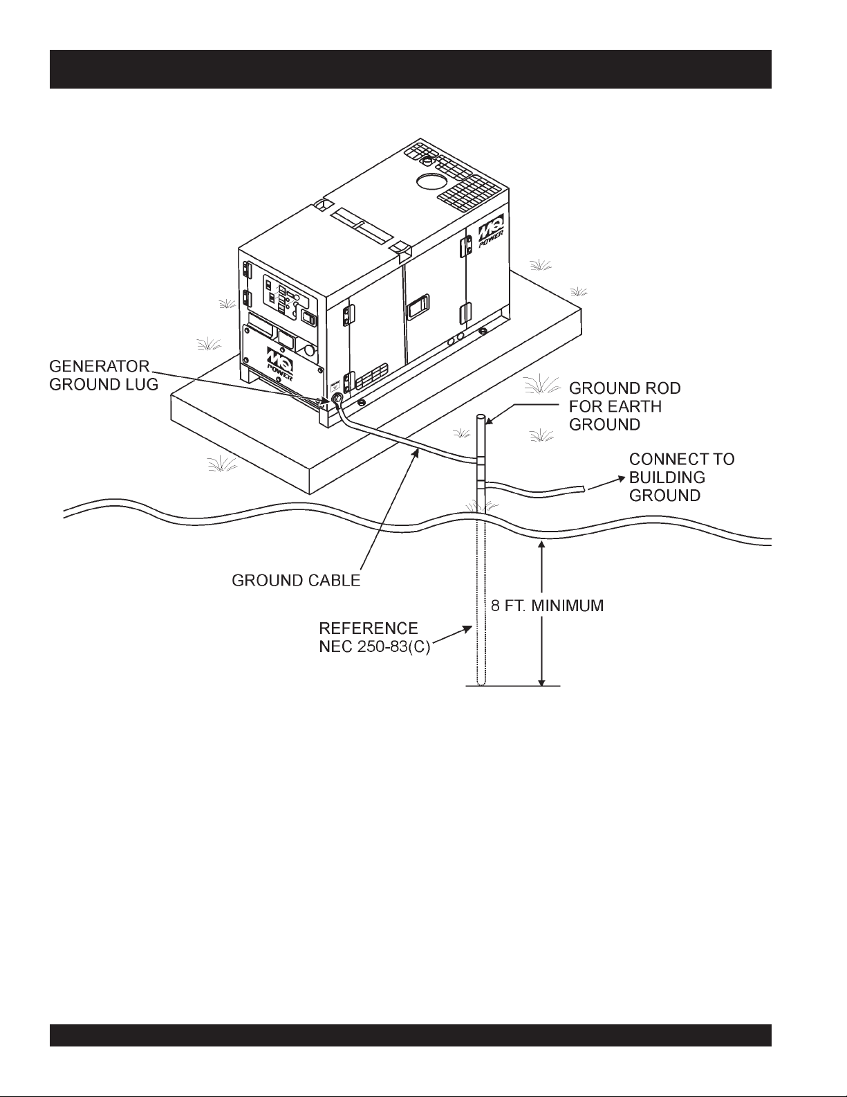
Figure 2. Typical Generator Grounding Application
DCA-70SSJU— INSTALLATION
DCA-70SSJU SERIES — OPERATION AND PARTS MANUAL (STD)— REV. #5 (06/03/03) — PAGE 15
1
Outdoor Installation
Install the generator in a area that is free of debris,
bystanders, and overhead obstructions. Make sure the
generator is on secure level ground so that it cannot slide or
shift around. Also install the generator in a manner so that
the exhaust will not be discharged in the direction of nearby
homes.
The installation site must be relatively free from moisture
and dust. All electrical equipment should be protected from
excessive moisture. Failure to do will result in deterioration
of the insulation and will result in short circuits and grounding.
Foreign materials such as dust, sand, lint and abrasive
materials have a tendency to cause excessive wear to
engine and alternator parts.
CAUTIONCAUTION
CAUTIONCAUTION
CAUTION
:
Pay close attention to ventilation when
operating the generator inside tunnels and
caves. The engine exhaust contains
noxious elements. Engine exhaust must
be routed to a ventilated area.
Indoor Installation
Exhaust gases from diesel engines are extremely poisonous.
Whenever an engine is installed indoors the exhaust fumes
must be vented to the outside. The engine should be installed
at least two feet from any outside wall. Using an exhaust
pipe which is too long or too small can cause excessive
back pressure which will cause the engine to heat
excessively and possibly burn the valves.
Mounting
The generator must be mounted on a solid foundation (such
as concrete) and set firmly on the foundation to isolate
vibration of the generator when it is running. The generator
must set at least 6 inches above the floor or grade level (in
accordance to NFPA 110, Chapter 5-4.1). DO NOT remove
the metal skids on the bottom of the generator. They are to
resist damage to the bottom of the generator and to maintain
alignment.
Generator Grounding
To guard against electrical shock and possible damage to
the equipment, it is important to provide a good EARTH
ground.
Article 250 (Grounding) of the National Electrical Code (NEC)
provides guide lines for proper grounding and specifies that
the cable ground shall be connected to the grounding system
of the building as close to the point of cable entry as
practical.
NEC articles 250-64(b) and 250-66 set the following
grounding requirements:
1. Use one of the following wire types to connect the
generator to earth ground.
a. Copper - 10 AWG (5.3 mm
2
) or larger.
b. Aluminum - 8 AWG (8.4 mm
2
) or larger.
2. When grounding the generator (Figure 2) connect the
ground cable between the lock washer and the nut on
the generator and tighten the nut fully. Connect the other
end of the ground cable to earth ground.
3. NEC article 250-52(c) specifies that the earth ground
rod should be buried aminimum of 8 ft. into the ground.
When connecting the generator to
any buildings electrical system
ALWAYS consult with a licensed
electrician.
DCA-70SSJU— INSTALLATION
NOTE
PAGE 16 — DCA-70SSJU SERIES — OPERATION AND PARTS MANUAL (STD) — REV. #5 (06/03/03)
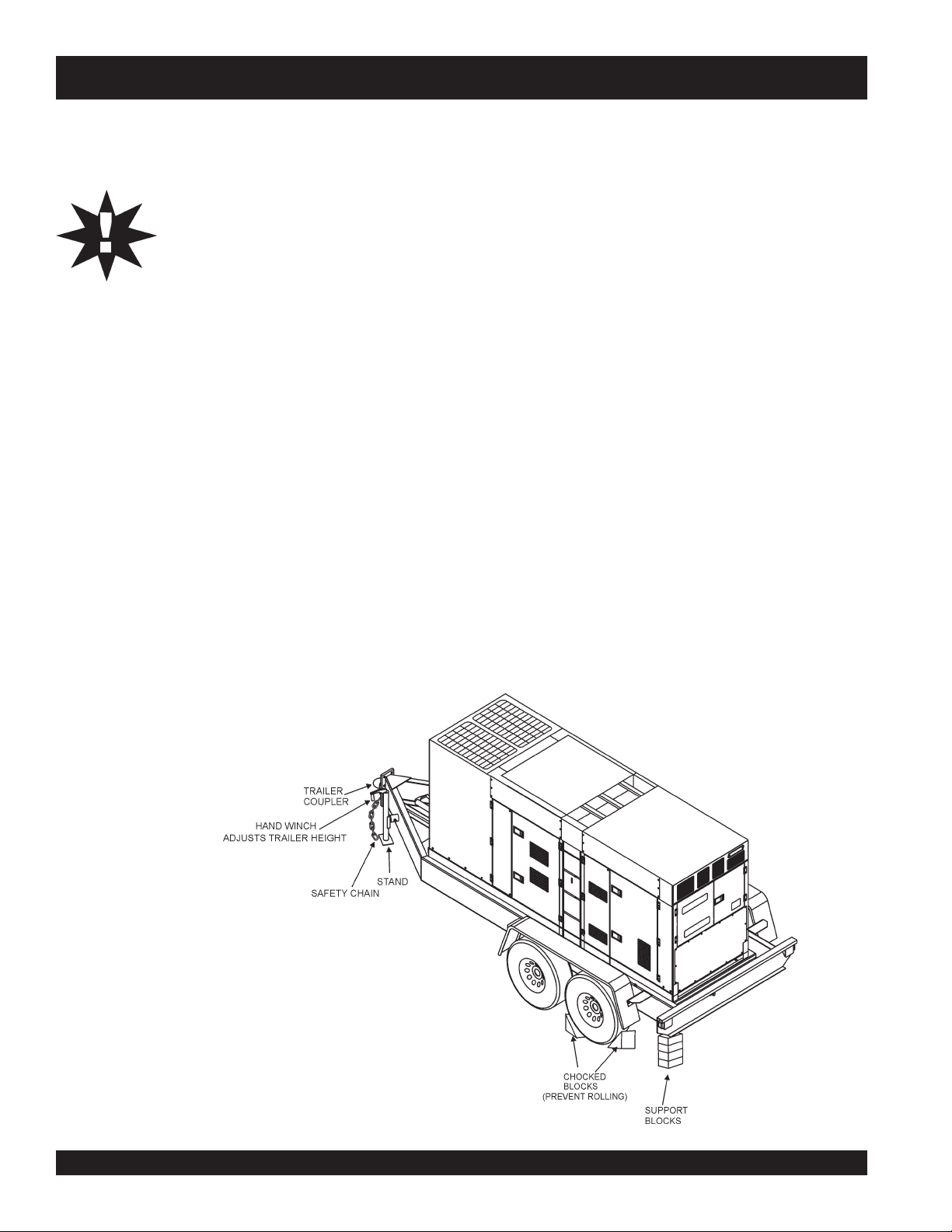
To reduce the possibility of an accident while transporting
the generator on public roads, always make sure the trailer
(Figure 4) that supports the generator and the towing vehicle
are in good operating condition and both units are
mechanically sound.
The following list of suggestions should be used when towing
your generator:
CAUTIONCAUTION
CAUTIONCAUTION
CAUTION
:
Towing Safety Precautions
Check with your local county or state safety
towing regulations before towing your
generator.
■
Make sure the hitch and coupling of the towing vehicle
are rated equal to, or greater than the trailer "gross vehicle
weight rating" (GVWR).
■
ALWAYS inspect the hitch and coupling for wear. NEVER
tow a trailer with defective hitches, couplings, chains
etc.
■
Check the tire air pressure on both towing vehicle and
trailer. Also check the tire tread wear on both vehicles.
■
ALWAYS make sure the trailer is equipped with a "Safety
Chain".
DCA-70SSJU SERIES — TOWING SAFETY PRECAUTIONS
■
ALWAYS attach trailer’s safety chain to bumper of towing
vehicle.
■
ALWAYS make sure the vehicle and trailer directional,
backup, brake, and trailer lights are connected and
working properly.
■
The maximum speed for highway towing is 55 MPH
unless posted otherwise. Recommended off-road towing
is not to exceed 15 MPH or less depending on type of
terrain.
■
Place
chocked blocks
underneath wheel to prevent
rolling, while parked.
■
Place
support blocks
underneath the trailer’s bumper to
prevent tipping, while parked.
■
Use the trailer’s hand winch to adjust the height of the
trailer, then insert locking pin to lock wheel stand in place,
while parked.
■
Avoid sudden stops and starts. This can cause skidding,
or jackknifing. Smooth, gradual starts and stops will
improve gas milage.
■
Avoid sharp turns to prevent rolling.
■
Remove wheel stand when transporting.
■
DO NOT transport generator with fuel in tank.
Figure 3. Generator with Trailer

DCA-70SSJU SERIES — OPERATION AND PARTS MANUAL (STD)— REV. #5 (06/03/03) — PAGE 17
1
Explanation of Chart:
This section is to provide the user with trailer service and
maintenance information. The service and maintenance
guidelines referenced in this section apply a wide range of
trailers. Remember periodic inspection of the trailer will en-
sure safe towing of the equipment and will prevent damage
to the equipment and personal injury.
It is the purpose of this section to cover the major mainte-
nance components of the trailer. The following trailer com-
ponents will be discussed in this section:
Brakes
Tires
Lug Nut Torquing
Suspension
Electrical
Brake Troubleshooting Tables
Use the following definitions when reading Table 2.
1. Fuel Cell - Provides an adequate amount of fuel for the
equipment in use. Fuel cells must be empty when trans-
porting equipment.
2. Braking System - System employed in stopping the
trailer. Typical braking systems are electric, surge, hy-
draulic, hydraulic-surge and air.
3. GVWR- Gross Vehicle Weight Rating (GVWR), is the
maximum number of pounds the trailer can carry, in-
cluding the fuel cell (empty).
4. Frame Length - Measurement is from the ball hitch to
the rear bumper (reflector).
DCA-70SSJU SERIES — TRAILER SPECIFICATIONS
CAUTIONCAUTION
CAUTIONCAUTION
CAUTION
:
ALWAYS make sure the trailer is in good
operating condition. Check the tires for
proper inflation and wear. Also check the
wheel lug nuts for proper tightness.
5. Frame Length - Measurement is from fender to fender
6. Jack Stand - Trailer support device with maximum pound
requirement from the tongue of the trailer.
7. Coupler - Type of hitch used on the trailer for towing.
8. Tire Size - Indicates the diameter of the tire in inches
(10,12,14, etc.), and the width in millimeters
(175,185,205, etc.). The tire diameter must match the
diameter of the tire rim.
9. Tire Ply - The tire ply (layers) number is rated in letters;
2-ply,4-ply,6-ply, etc.
10. Wheel Hub - The wheel hub is connected to the trailer’s
axle.
11. Tire Rim - Tires mounted on a tire rim. The tire rim must
match the size of the tire.
12. Lug Nuts - Used to secure the wheel to the wheel hub.
Always use a torque wrench to tighten down the lug nuts.
See Table 17 and Figure 67
for lug nut tightening and
sequence.
13. Axle - Indicates the maximum weight the axle can sup-
port in pounds, and the diameter of the axle expressed
in inches. Please note that some trailers have a double
axle. This will be shown as 2-6000 lbs., meaning two
axles with a total weight capacity of 6000 pounds.
14. Suspension - Protects the trailer chassis from shocks
transmitted through the wheels. Types of suspension
used are leaf, Q-flex, and air ride.
15. Electrical - Electrical connectors (looms) are provided
with the trailer so the brake lights and turn signals can
be connected to the towing vehicle.
16. Application - Indicates which units can be employed
on a particular trailer.

PAGE 18 — DCA-70SSJU SERIES — OPERATION AND PARTS MANUAL (STD) — REV. #5 (06/03/03)
DCA-70SSJU SERIES — TRAILER SPECIFICATIONS
snoitacificepSreliarT.2elbaT
LEDOM NOITACILPPA LEUF
LLEC
EKARB
METSYS
RWVG EMARF
HTGNEL
EMARF
HTDIW
KCAJ
DNATS
W01-RLRT ,522WDS
-WLT,052WGS
003
ONONSBL0091"69"05.BL008
LEEHWTLITLLUF
01-RLRT ,01ACD
-ACD,21GLT
51
ONONSBL00
91"69"05.BL008
LEEHWTLITLLUF
FX01-RLRT -GLT,01ACD
,51ACD,21
003-WLT
LAG25ONSBL0091"69"05.BL008
LEEHWTLITLLUF
W522-RLR
T ,SREDLEW
SS0007AD
ONONSBL0022"58"24.BL008
LEEHWTLITLLUF
004WLB-RLRT 004-WLBONCIRTCELESBL0072TSAM/W
"451
"421O/W
"55
"8
7(
)LLAT
.BL008
LEEHWTLITLLUF
X05-RLRT 52-ACDONONSBL0072"421"55.BL008
LEEHWTLITLLUF
FX05-RLRT 52-ACDLAG14ONSBL0072"421"5
5.BL008
LEEHWTLITLLUF
W07-RLRT ,06-,54-ACD
07
ONEGRUSSBL0007"681"77.BL0002
DAPTALF
X07-RLRT ,06-,54-ACD
07
TPOEGRUSSBL0
007"831"66.BL0002
DAPTALF
FX07-RLRT ,06-,54-ACD
07
LAG35EGRUSSBL0007"831"66.BL0002
DAPTALF
FX001-RLRT 521,001-ACDLAG05
1CILUARDYH
EGRUS
SBL0007"091"67.BL0002
DAPTALF
521/58-RLRT ,001,58-ACD
521
LAG541CILUARDYHSBL00001"681"77.BL0002
DAPTA
LF
FX051-RLRT 081,051-ACDLAG002CILUARDYH
EGRUS
SBL06111"402"48.BL0005
DAPTALF
FX022-RLRT 022-ACDLAG052CILUARDYH
EGRU
S
SBL00041"222"38.BL0005
DAPTALF
FX003-RLRT 003-ACDLAG052CILUARDYH
EGRUS
SBL00081"832"38.BL0005
DAPTALF
FX004-RLRT 004
-ACDLAG053CIRTCELESBL00081"832"38.BL0005
DAPTALF
FX006-RLRT 008,006-ACDLAG055RIASBL00003"483"69.BL0005
DAPTALF
XS008-R
LRT 008,006-ACDLAG055RIASBL00003"483"69.BL0005
DAPTALF

DCA-70SSJU SERIES — OPERATION AND PARTS MANUAL (STD)— REV. #5 (06/03/03) — PAGE 19
1
DCA-70SSJU SERIES — TRAILER SPECIFICATIONS
)t'noC(snoitacificepS.2elbaT
LEDOM RELPUOC SERIT SLEEHW ELXA SBUH NOISNEPSUS LACIRTCELE
W01-RLRT SSALCLLAB"2
ELBATSUJDA2
C31-571"05.4X"312X2#0022GUL5FAEL3MOOLERIW4
/W
TALFELOP4
01-RLRT SSALCL
LAB"2
ELBATSUJDA2
C31-571"5.4X"312X2#0022GUL5FAEL3TALFELOP4
FX01-RLRT SSALCLLAB"2
ELBATSUJDA2
C31-571"5.4X"312X2#0
022GUL5FAEL3TALFELOP4
W522-RLRT SSALCLLAB"2
ELBATSUJDA2
B31-571"5.4X312X2#0022GUL5XELFQTALFELOP4
WLB-RLRT
004
SSALCL
LAB"2
ELBATSUJDA2
C31-571"5.4X312X2#0022GUL5FAEL3TALFELOP4
X05-RLRT SSALCLLAB"2CRL31-87B"05.4X"31.sbl0053
"8/3-2
GU
L5FAEL4ELOP4
TALFREBBUR
FX05-RLRT SSALCLLAB"2CRL31-87B"05.4X"31.sbl0053
"8/3-2
GUL5FAEL4ELOP4
TALFREBBUR
W07-RLRT SS
ALCLLAB"2
ELBATSUJDA"3
C41-502
)4(SAIB
"5X"41.sbl0053
"3
GUL5FAEL5ELOP4
TALFREBBUR
X07-RLRT SSALCLLAB"2
ELBATSUJDA
"3
C41-502
)4(SAIB
"5X"41sbl0053
"3
GUL5FAEL5ELOP4
TALFREBBUR
FX07-RLRT SSALCLLAB"2
ELBATSUJDA"3
C41-502
)4(SAIB
"5X
"41.sbl0053
"3
GUL5FAEL5ELOP4
TALFREBBUR
FX001-RLRT -2ELBATSUJDA
EYE"3TPO6/5
C51-502
)4(SAIB
"5.5X"41sbl0053
"3
GUL5F
AEL5MOOLERIW4
521/58-RLRT -2ELBATSUJDA
EYE"3TPO6/5
D51R57/522TS
)4(LAIDAR
"6x"41sbl0006-)2(GUL6FAEL7MOOLERIW4
FX0
51-RLRT EYELLAB"3E61-057
)4(SAIB
"7X"61sbl0006-)2(GUL8FAEL7MOOLERIW4
FX022-RLRT EYE"3
ELBATSUJDA
E61R58/532TS
)4(L
AIDAR
"7X"61sbl0007-)2(GUL8XELFQMOOLERIW4
FX003-RLRT EYE"3
ELBATSUJDA
E61R58/532TS
)6(LAIDAR
"7X"61sbl0006-)2(GUL8X
ELFQMOOLERIW4
FX004-RLRT EYE"3
ELBATSUJDA
E61R58/532TS
)6(LAIDAR
"7X"61-bl0007-)3(
.s
GUL8XELFQMOOLERIW4
FX006-RLR
T LEEHWHT5H5.71R57/512TS
)8(LAIDAR
"7X"61-l00001-)3(
sb
GUL8FAEL7MOOLERIW6
RA008-RLRT LEEHWHT5H5.71R57/512TS
)8(LA
IDAR
"7X"61-l00001-)3(
sb
GUL8EDIR-RIAMOOLERIW6
PAGE 20 — DCA-70SSJU SERIES — OPERATION AND PARTS MANUAL (STD) — REV. #5 (06/03/03)
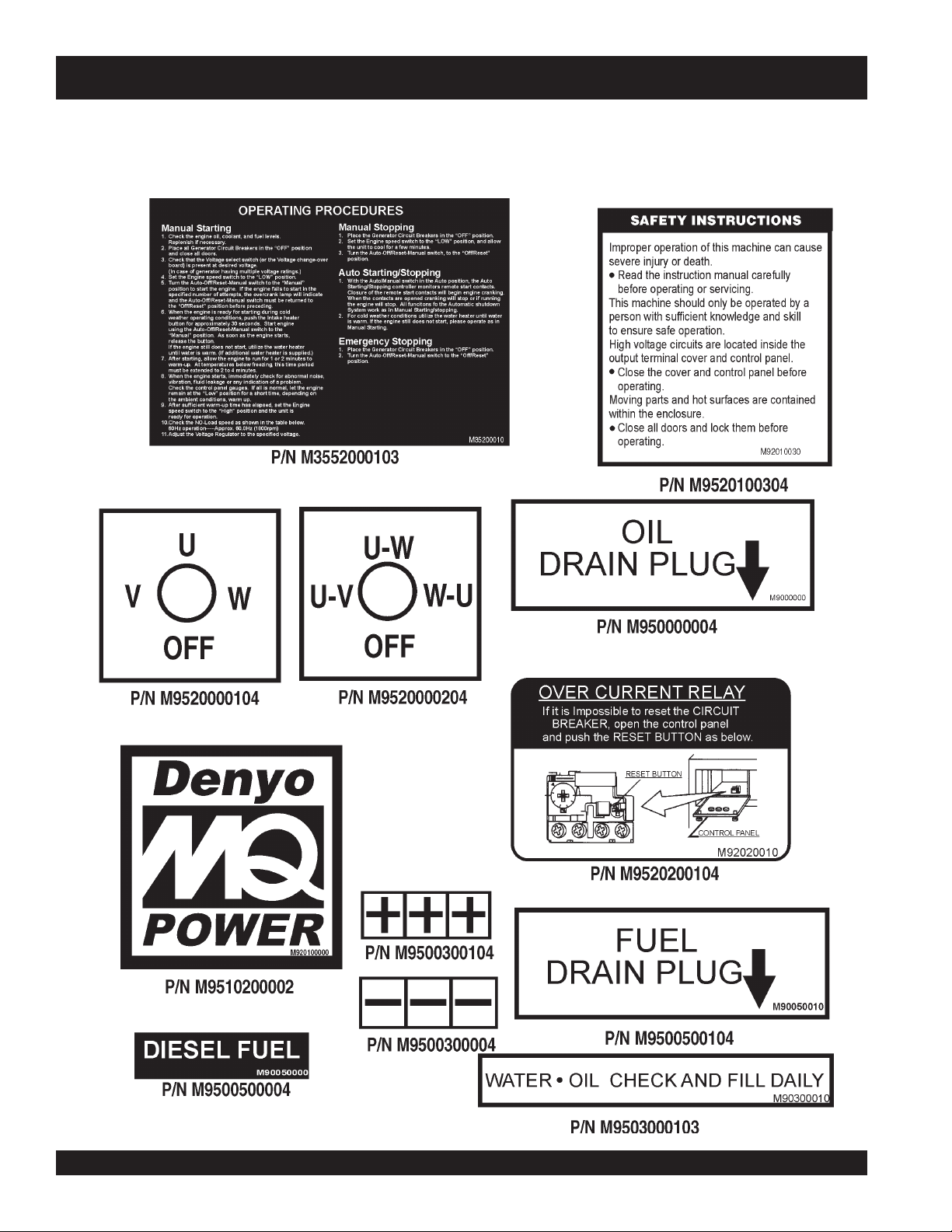
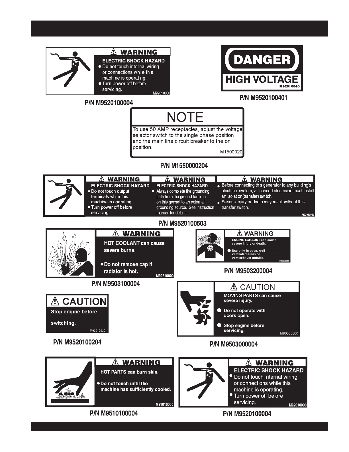
The DCA-70SSJU Series generator is equipped with a number of safety decals. These decals are provided for operator
safety and maintenance information. The illustration below and on the preceding page show the decals as they appear on
the machine. Should any of these decals become unreadable, replacements can be obtained from your dealer.
DCA-70SSJU SERIES — GENERATOR DECALS
DCA-70SSJU SERIES — OPERATION AND PARTS MANUAL (STD)— REV. #5 (06/03/03) — PAGE 21
1
DCA-70SSJU SERIES — GENERATOR DECALS

PAGE 22 — DCA-70SSJU SERIES — OPERATION AND PARTS MANUAL (STD) — REV. #5 (06/03/03)
DCA-70SSJU SERIES — GENERAL INFORMATION
DCA-70SSJU Series Familiarization
Generator
The MQ Power Model DCA-70SSJU Series is a 26 kW
generator
(Figure 4) that is designed as a high quality
portable (requires a trailer for transport) power source for
telecom sites, lighting facilities, power tools, submersible
pumps and other industrial and construction machinery.
Engine Operating Panel
The “Engine Operating Panel” is provided with the following:
Tachometer
Water Temperature Gauge
Oil Pressure Gauge
Charging Ammeter Gauge
Engine Throttle Handle (Up to S/N 7302410)
Fuel Level Gauge
Engine Speed Switch (S/N 7302141~)
Cold Starting Button
Panel Light
Panel Light Switch
Ignition/Preheat Switch ( Up to S/N 7302410)
Auto ON/OFF Engine Controller (S/N 7302141~)
Generator Control Panel
The “Generator Control Panel” is provided with the following:
Output Voltage Adjustment Knob
Frequency Meter (Hz)
AC Ammeter (Amps)
AC Voltmeter (Volts)
Ammeter Change-Over Switch
Voltmeter Change-Over Switch
Voltage Regulator
Over-Current Relay
Output Terminal Panel
The “Output Terminal Panel” is provided with the following:
Three 250 VAC output receptacles (CS-6369), 50 amps
Three auxilliary circuit breakers, 250V @50 amps
Two 125 VAC output receptacles, (GFCI), 20 amps
Two GFCI circuit breakers, 120V@ 20amps
Five output terminal lugs (3Ø power)
Control Box
The “Control Box” is provided with the following:
3-Pole, 250 VAC, 175 amp Main Circuit Breaker
Automatic Voltage Regulator
Current Transformer
Emergency Relay
Open Delta Excitation System
The DCA-70SSJU Series generator is equipped with the state
of the art "
Open-Delta
" excitation system. The open delta
system consist of an electrically independent winding wound
among stationary windings of the AC output section.
There are four connections of the open delta A, B, C and D.
During steady state loads, the power from the voltage regulator
is supplied from the parallel connections of A to B, A to D, and
C to D. These three phases of the voltage input to the voltage
regulator are then rectified and are the excitation current for the
exciter section.
When a heavy load, such as a motor starting or a short circuit
occurs, the automatic voltage regulator (AVR) switches the
configuration of the open delta to the series connection of B to
C. This has the effect of adding the voltages of each phase ot
provide higher excitation to the exciter section and thus better
voltage response during the application of heavy loads.
The connections of the AVR to the AC output windings are for
sensing only. No power is required from these windings.
The open-delta design provides virtually unlimited excitation
current, offering maximum motor starting capabilities. The
excitation does not have a "
fixed ceiling
" and responds
according the demands of the required load.
Engine
The DCA-70SSJU and DCA-70SSJU2 are powered by a 4
cycle, water cooled, turbocharged JOHN DEERE
Model
4045TF150 Diesel
Engine. This engine is designed to meet
every performance requirement for the generator. Reference Table
1 for engine specifications.
In keeping with MQ Power's policy of constantly improving its
products, the specifications quoted herein are subject to change
without prior notice.
Mechanical Governor System
The mechanical governor system control the RPM of the
engine. When the engine demands increase or decrease, the
mechanical governor system regulates the frequency varia-
tion to ±.5%. The electronic governor option increases
frequency variation to ±0.25%.
Extension Cables
When electric power is to be provided to various tools or loads
at some distance from the generator, extension cords are
normally used. Cables should be sized to allow for distance in
length and amperage so that the voltage drop between the
generator and point of use (load) is held to a minimum. Use the
cable selection chart (Table 5) as a guide for selecting proper
extension cable size.
DCA-70SSJU SERIES — OPERATION AND PARTS MANUAL (STD)— REV. #5 (06/03/03) — PAGE 23
1
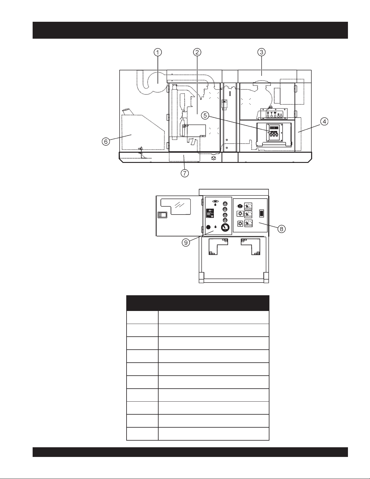
DCA-70SSJU SERIES — MAJOR COMPONENTS
Figure 4. Major Components
3elbaT. stnenopmoCrojaMrotareneG
.ONMETINOITPIRCSED
1ylbmessArelffuM
2ylbmessAenignE
3ylbmessAerusolcnE
4ylbmessArotareneG
5ylbmessAlanimreTtuptu
O
6ylbmessAknaTleuF
7ylbmessAyrettaB
8ylbmessAlenaPlortnoCrotareneG
9ylbmessAlenaPgnitarepOenignE
PAGE 24 — DCA-70SSJU SERIES — OPERATION AND PARTS MANUAL (STD) — REV. #5 (06/03/03)
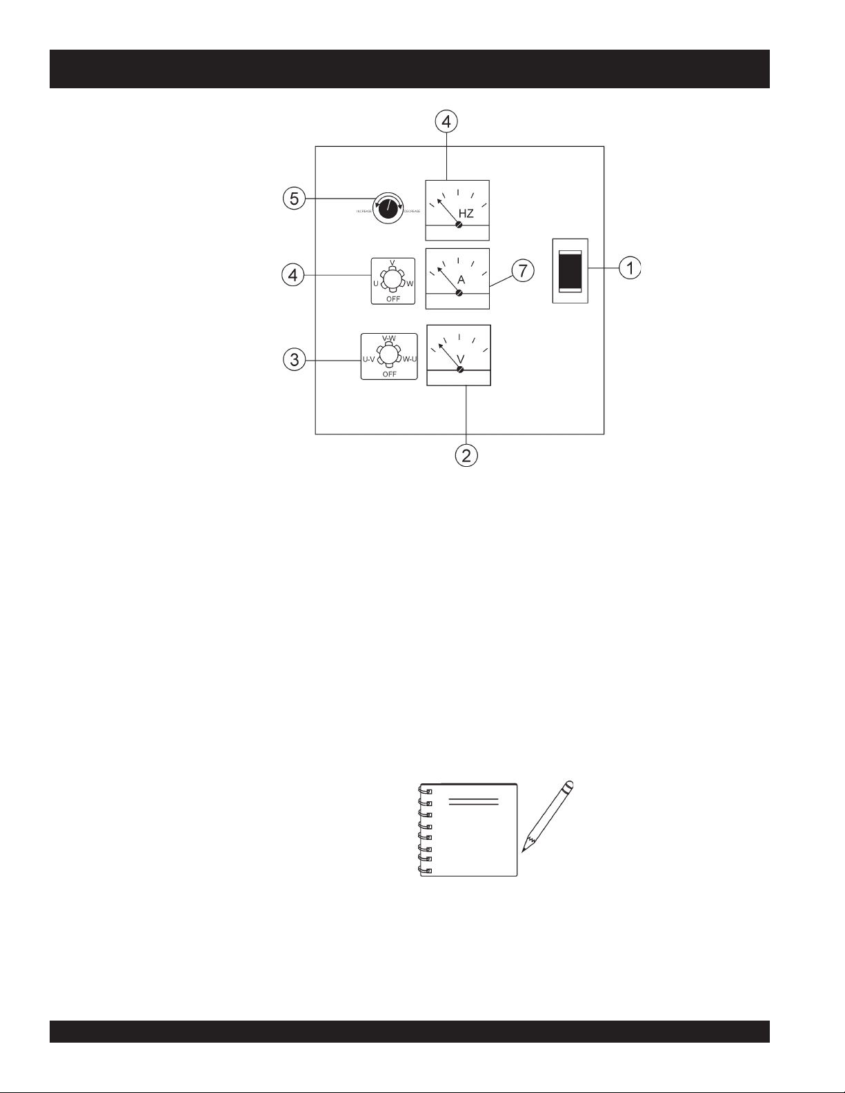
DCA-70SSJU SERIES — GENERATOR CONTROL PANEL
The definitions below describe the controls and functions of
the DCA-70SSJU Series "
Generator Control Panel
"
(Figure 5).
1. Main Circuit Breaker – This three-pole, 175 amp main
breaker is provided to protect the UVWO output
terminals from overload.
2. AC Ammeter – Indicates the amount of current the
load is drawing from the generator per leg selected by
the ammeter phase-selector switch.
3. Ammeter Change-Over Switch – This switch allows
the AC ammeter to indicate the current flowing to the
load connected to any phase of the output terminals, or
to be switched off. This switch does not effect the
generator output in any fashion, it is for current reading
only.
4. Voltmeter Change-Over Switch – This switch allows
the AC voltmeter to indicate phase to phase voltage
between any two phases of the output terminals or to
be switched off.
5. Voltage Regulator Control – Allows ±15% manual
adjustment of the generator’s output voltage.
6. Frequency Meter – Indicates the output frequency in
hertz (Hz). Normally 60 Hz ±1 Hz .
7. AC Voltmeter – Indicates the output voltage present
at the UVWO terminals.
Located behind the generator control panel is the
Generator
Control Box
. This box contains some of the necessary
electronic components required to make the genertator
function.
The “Control Box” is equipped with the following major
components:
Over-Current Relay
Voltage Rectifer
Starter Relay
Engine Controller (Computer Controlled)
Current Transformer
Voltage Selector Switch
Remember the
overcurrent
relay
monitors the current
flowing from the UWVO output
terminals to the load.
In the event of a short circuit or
over current condition, it will
automatically trip the main 250
amp breaker.
NOTE
To restore power to the UWVO output terminals, press the
reset
button on the overcurrent relay and place the
main
circuit breaker in the
closed
position (ON).
Figure 5. Generator Control Panel
DCA-70SSJU SERIES — OPERATION AND PARTS MANUAL (STD)— REV. #5 (06/03/03) — PAGE 25
1
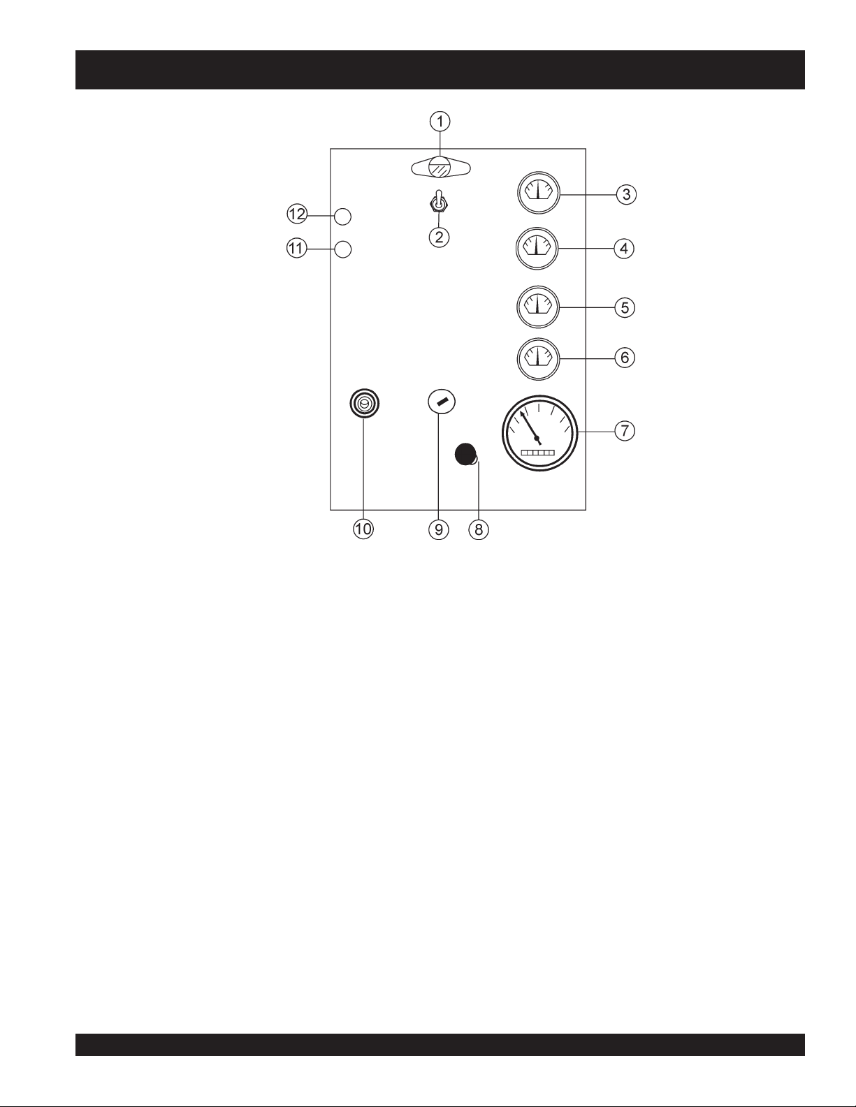
DCA-70SSJU SERIES — ENGINE OPERATING PANEL
The definitions below describe the controls and functions of
the DCA-70SSJU - "
Engine Operating Panel
" (Figure 6), up
to S/N 73002140.
1. Panel Light – Normally used in dark areas or at night
time. When activated, panel lights will illuminate. When
the generator is not in use be sure to turn the panel
light switch to the OFF position.
2. Panel Light Switch – When activated will turn on control
panel light.
3. Oil Pressure Gauge – During normal operation this
gauge be should read in the “GREEN” zone. When
starting the generator the oil pressure may read a little
bit higher, but after the engine warms up the oil pressure
should return to the green zone.
4. Water Temperature Gauge – During normal operation
this gauge be should read in the “GREEN” zone.
5. Charging Ammeter Gauge – Indicates the current
being supplied by the engine’s alternator which provides
current for generator’s control circuits and battery
charging system.
6. Fuel Gauge - Indicates amount of diesel fuel available.
7. Tachometer – Indicates engine speed in RPM’s for 60
Hz operation. This meter should indicate 1800 RPM’s
when the rated load is applied. In addition a built in hour
meter will record the number of operational hours that
the generator has been in use.
8. Engine Speed Throttle- This lever controls the speed
of the engine (low or high).
9. Ignition Switch – Turns the engine on, off or to preheat
the engine.
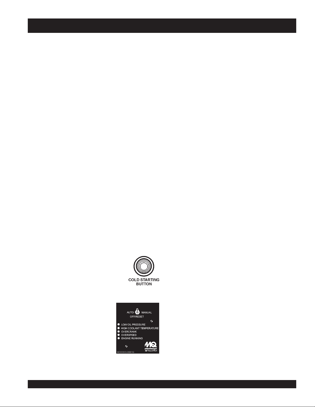
10. Cold Starting Button – Used to warm the engine glow
plugs in cold weather conditions. Press and hold the
engine cold starting button until the button illuminates.
11. Water Temperature Warning Light - Indicates if the
coolant is low. This warning will shut off the engine.
12. Oil Pressure Warning Light - This will indicate if the
oil pressure is too low or high. This warning will shut off
the engine.
Figure 6. Engine Operating Panel Up To
S/N 73002140
PAGE 26 — DCA-70SSJU SERIES — OPERATION AND PARTS MANUAL (STD) — REV. #5 (06/03/03)
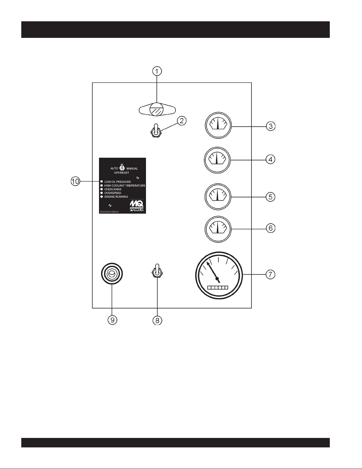
Figure 7. Engine Operating Panel From
S/N 73002141~
DCA-70SSJU SERIES — ENGINE OPERATING PANEL
DCA-70SSJU SERIES — OPERATION AND PARTS MANUAL (STD)— REV. #5 (06/03/03) — PAGE 27
1
DCA-70SSJU SERIES — ENGINE OPERATING PANEL
The definitions below describe the controls and functions of
the DCA-70SSJU2 "
Engine Operating Panel
" (Figure 7)
from S/N 73002141~.
1. Panel Light – Normally used in dark areas or at night
time. When activated, panel lights will illuminate. When
the generator is not in use be sure to turn the panel
light switch to the OFF position.
2. Panel Light Switch – When activated will turn on control
panel light.
3. Oil Pressure Gauge – During normal operation this
gauge be should read between 42 to 71 psi. When
starting the generator the oil pressure mar read a little
bit higher, but after the engine warms up the oil pressure
should return to the green zone.
4. Water Temperature Gauge – During normal operation
this gauge be should read between 165
o
and 203
o
F.
5. Charging Ammeter Gauge – Indicates the current
being supplied by the engine’s alternator which provides
current for generator’s control circuits and battery
charging system.
6. Fuel Gauge - Indicates amount of diesel fuel available.
7. Tachometer – Indicates engine speed in RPM’s for 60
Hz operation. This meter should indicate 1800 RPM’s
when the rated load is applied. In addition a built in hour
meter will record the number of operational hours that
the generator has been in use.
8. Engine Speed Switch - This switch controls the speed
of the engine (low or high).
9. Cold Starting Button – Used to warm
the engine glow plugs in cold weather
conditions. Press and hold the engine
cold starting button until the button
illuminates.
10. Auto On/Off Engine
Controller – This controller as
a vertical row of status LED's
(inset), that when lit, indicate
that an engine malfunction
(fault), has been detected.
When a fault has been detected
the engine controller will
evaluate the fault and all major
faults will shutdown the
generator.
A. Off/Manual/Auto Switch – This switch controls the
running of the generator. If this switch is left in the "OFF"
position, the generator will not run. When this switch is
set to the
manual
position, the generator will start
immediately.
If the generator is to be connected to a building's AC
power source via a transfer switch (isolation), place
the switch in the
auto
position. In this position the
generator will monitor the AC line output from the
building's power source.
B. Low Oil Pressure – Indicates the engine pressure
has fallen below 15 psi. The oil pressure is detected
using variable resistive values from the oil pressure
sending unit. This is considered a
major
fault.
C. High Coolant Temperature – Indicates the engine
temperature has exceeded 215
°
F. The engine
temperature is detected using variable resistive values
from the temperature sending unit. This is considered
a
major
fault.
D. Overcrank Shutdown – Indicates the unit has
attempted to start a pre- programmed number of times,
and has failed to start. The number of cycles and
duration are programmable. It is pre-set at 3 cycles
with a 10 second duration. This is considered a
major
fault.
E. Overspeed Shutdown – Indicates the engine is running
at an unsafe speed. This is considered a
major
fault.
F. Engine Running – Indicates that engine is running at
a safe operating speed.
During
cranking cycle
, The MPEC will attempt to crank the
engine for 10 seconds before disengaging. If the engine does
not engage (start) by the third attempt, the engine will be
shutdown by the engine controller’s "OVER CRANK
PROTECTION" mode. If the engine engages at a speed
(RPM's) that is not safe, the controller will shutdown the
engine by initializing the "Over Speed Protection" mode.
Also the engine controller will shutdown the generator in the
event of low oil pressure, high coolant temperature, low
coolant level, and loss of magnetic pickup. These conditions
can be observed by monitoring the LED status indicators on
the front of the controller module.
PAGE 28 — DCA-70SSJU SERIES — OPERATION AND PARTS MANUAL (STD) — REV. #5 (06/03/03)
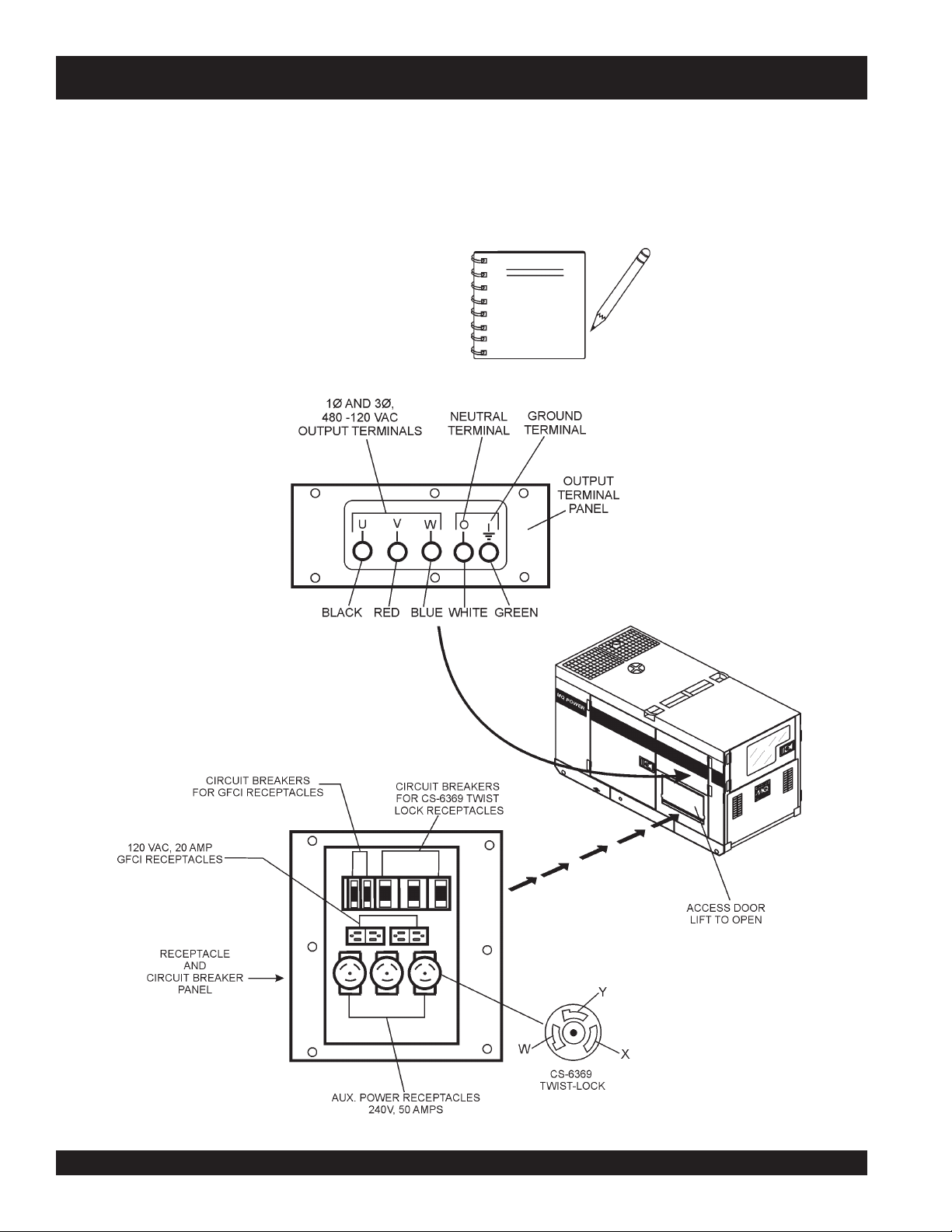
Output Terminal Familiarization
The “
Output Terminal Panel
” (Figure 8) is provided with
the following:
Three (3) 240V output receptacles, 50 amp
Three (3) Circuit Breakers 240V @50 amps
Two (2) 120V GFCI receptacles, 20 amp
Two (2) GFCI Circuit Breakers 120V@ 20 amps
One Main Circuit Breaker 250V @175 amps
Five (5) Output Terminal Lugs
Output Terminal Panel
The
Output Terminal Panel
(Figure 8) shown below is located
on the right-hand side (left from control panel) of the generator.
Lift up on the cover to gain access to receptacles and terminal
lugs.
NOTE
Terminal legs “O” and “Ground”
are considered
bonded grounds
.
Figure 8. Output Terminal Panel
DCA-70SSJU SERIES — OUTPUT TERMINAL PANEL FAMILIARIZATION
DCA-70SSJU SERIES — OPERATION AND PARTS MANUAL (STD)— REV. #5 (06/03/03) — PAGE 29
1
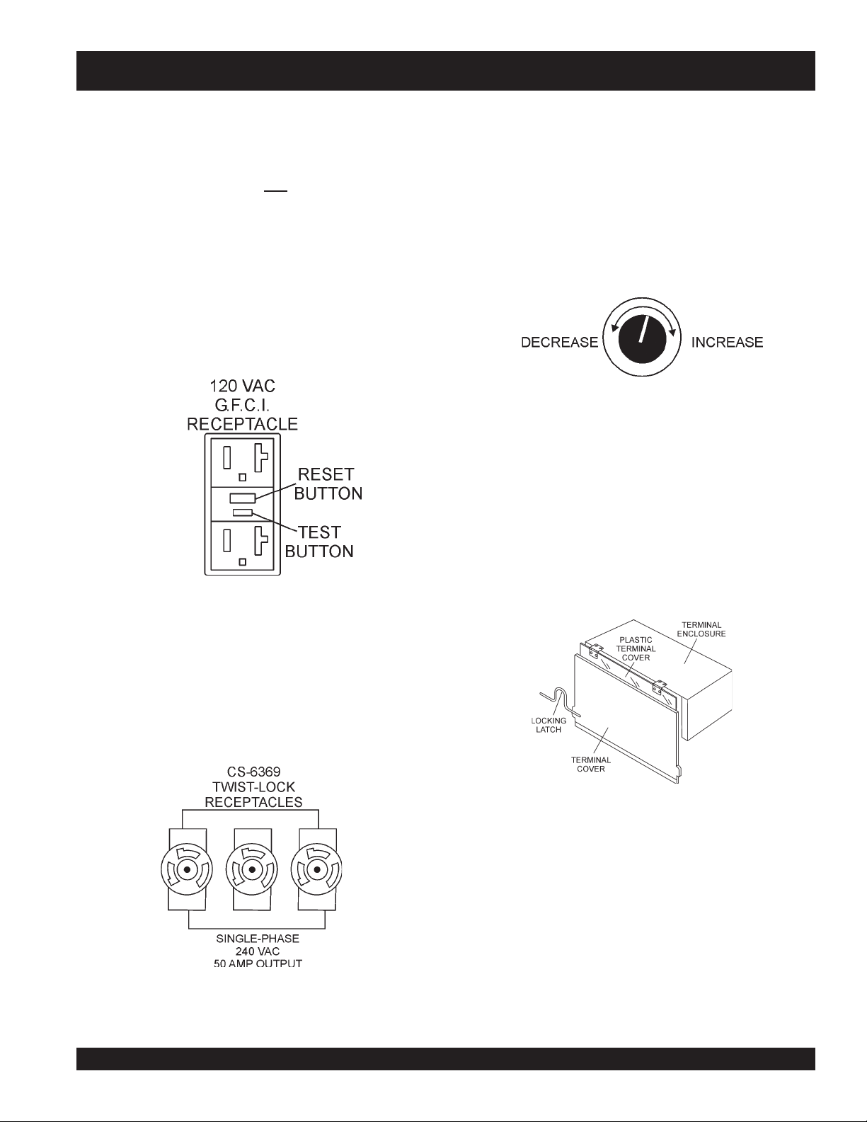
120 VAC GFCI Receptacles
There are two 120 VAC, 20 amp GFCI (Duplex Nema 5-20R)
recepacles provided on the output terminal panel. These
receptacles can be accessed in any
voltage selector switch
position. Each receptacle is protected by a 20 amp circuit
breaker. These breakers are located directly above the GFCI
receptacles. Remember the load output (current) of both
GFCI receptacles is dependent on the load requirements of
the UVWO terminals.
Pressing the
reset
button resets the GFCI receptacle after
being tripped. Pressing the "
Test Button
" (See Figure 9) in
the center of the receptacle will check the GFCI function.
Both receptacles should be tested at least once a month.
Figure 9. G.F.C.I. Receptacle
Each auxilliary receptacle is protected by a 50 amp circuit
breaker. These breakers are located directly above the GFCI
receptacles. Remember the load output (current) on all three
receptacles is dependent on the load requirements of the
UVWO terminals.
Turn the
voltage regulator control knob
(Figure 11) on the
control panel to obtain the desired voltage. Turning the knob
clockwise will
increase
the voltage, turning the knob counter-
clockwise will
decrease
the voltage.
Figure 10. 240 VAC Twist-Lock
Auxiliary Receptacles
DCA-70SSJU SERIES — OUTPUT TERMINAL PANEL FAMILIARIZATION
Twist Lock Dual Voltage 120/240 VAC Receptacles
There are three 240 VAC, 50 amp auxilliary twist-lock (CS-
6369) recepacles (Figure 10) provided on the output terminal
panel.These receptacles can
only
be accessed when the
voltage selector switch is placed in the
single-phase 240/
120 position.
Removing the Plastic Face Plate (UVWO Terminals)
The UVWO terminal lugs are protected by a plastic face
plate cover (Figure 12). Un-lock the locking latch, and lift the
terminal cover to gain access to the plastic face plate.
Remove the screws securing the face plate to the terminal
enclosure, then lift the plastic hinged face plate.
After the load wires have been securely attached to the
UVWO terminals, reinstall the plastic face plate. Place the
terminal cover in the down position and secure the locking
latch.
Figure 11. Voltage Regulator Control Knob
Figure 12. Plastic Face Plate (UVWO Terminals)
PAGE 30 — DCA-70SSJU SERIES — OPERATION AND PARTS MANUAL (STD) — REV. #5 (06/03/03)
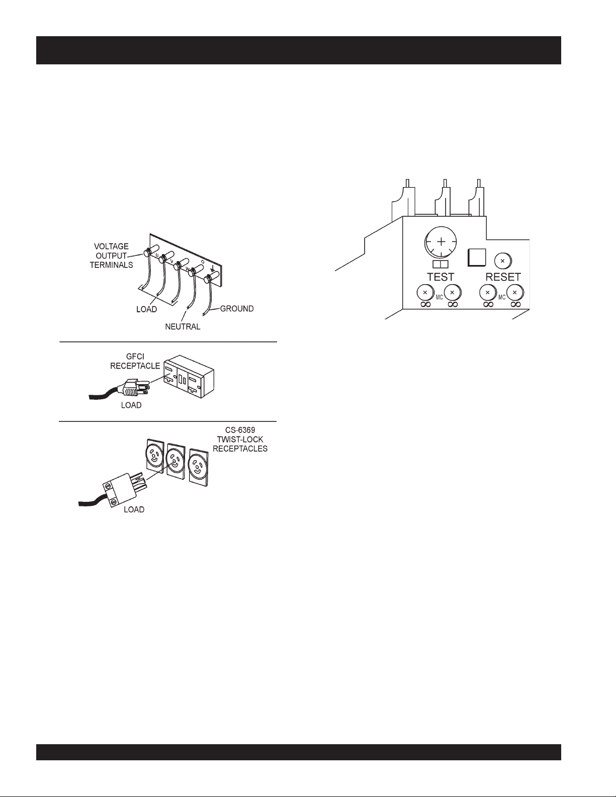
Figure 13. Connecting Loads
Connecting Loads
Loads can be connected to the generator by the UVWO terminal
lugs or the convienience receptacles. (See Figure 13). Make
sure to read the operation manual before attempting to connect
a load to the generator.
To protect the UVWO output terminals from overload, a 3-
pole, 175 amp,
main
circuit breaker is provided. Make sure
to switch
ALL
circuit breakers to the "OFF" position prior to
starting the engine.
DCA-70SSJU SERIES — OUTPUT TERMINAL PANEL FAMILIARIZATION
Over Current Relay
An
over current relay
(Figure 14) is connected to the main
circuit breaker. In the event of an overload, both the circuit
breaker and the over current relay may trip. If the circuit
breaker can not be reset, the
reset button
on the over cur-
rent relay must be pressed. The over current relay is lo-
cated in the control box.
Figure 14. Over Current Relay
 Loading...