


OPERATION AND PARTS MANUAL
WHISPERWATTTM SERIES
MODEL DCA-220SSJ
60 Hz GENERATOR
PARTS LIST NO. C1870300404
Revision #1 (03/22/07)
THIS MANUAL MUST ACCOMPANY THE EQUIPMENT AT ALLTIMES.
PAGE 2 — DCA-220SSJ— OPERATION AND PARTS MANUAL — REV. #1 (03/22/07)

NOTE PAGE
DCA-220SSJ— OPERATION AND PARTS MANUAL — REV. #1 (03/22/07) — PAGE 3

MQ POWER DCA-220SSJ
WHISPERWATTTM GENERATOR
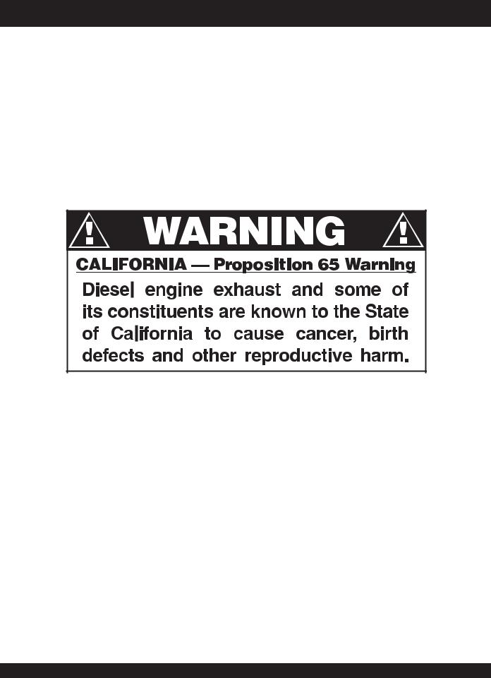
California Proposition 65 Warning ..................................... |
2 |
Table Of Contents ............................................................. |
4 |
Parts Ordering Procedures ............................................... |
5 |
Specifications ................................................................... |
6 |
Dimensions (Top, Side, Front) ........................................... |
7 |
Safety Message Alert Symbols .................................... |
8-9 |
Rules for Safe Operation ........................................... |
10-13 |
Generator Decals....................................................... |
14-15 |
Installation ................................................................. |
16-17 |
General Information ........................................................ |
18 |
Major Components ......................................................... |
19 |
Diagnostic Display ..................................................... |
20-36 |
Generator Control Panel ................................................. |
37 |
Engine Operating Panel ............................................. |
38-39 |
Output Terminal Panel Familiarization ........................ |
40-42 |
Load Application ............................................................. |
43 |
Generator Outputs .......................................................... |
44 |
Gauge Reading ............................................................... |
45 |
Output Terminal Panel Connections ................................ |
46 |
Setup .............................................................................. |
47 |
Generator Start-up Procedure (Manual) ..................... |
52-54 |
Generator Start-up Procedure (Auto Mode) .................... |
55 |
Generator Shut-Down Procedure .................................... |
56 |
Maintenance (Engine) ................................................ |
57-58 |
Maintenance Jacket Water Heater/Battery Charger ........ |
59 |
Maintenance (Trailer) ................................................. |
60-63 |
Trailer Wiring Diagram ..................................................... |
64 |
Generator Wiring Diagram ............................................... |
65 |
Engine Wiring Diagram ................................................... |
66 |
GeneratorTroubleshooting .............................................. |
67 |
Engine Controller Troubleshooting ................................... |
68 |
Explanation of Code in Remarks Column ....................... |
70 |
Suggested Spare Parts .................................................. |
71 |
TABLE OF CONTENTS
COMPONENT DRAWINGS
Generator Assembly .................................................. |
72-74 |
Control Panel Assembly ............................................ |
76-77 |
Control Box Assembly ............................................... |
78-81 |
Engine and Radiator Assembly ................................. |
82-87 |
Output Terminal Assembly ......................................... |
88-89 |
Battery Assembly ...................................................... |
90-91 |
Muffler Assembly ...................................................... |
92-93 |
Fuel Tank Assembly .................................................. |
94-95 |
Enclosure Assembly ............................................... |
96-101 |
Rubber Seals Assembly ........................................ |
102-103 |
Nameplate and Decals .......................................... |
104-105 |
Terms and Condition of Sale — Parts .......................... |
106 |
Specification and part NOTE number are subject to
change without notice.
PAGE 4 — DCA-220SSJ— OPERATION AND PARTS MANUAL — REV. #1 (03/22/07)
PARTS ORDERING PROCEDURES
When ordering parts,
please supply the following information:
Dealer account number
Dealer name and address
Shipping address (if different than billing address)Return fax number
Applicable model number
Quantity, part number and description of each partSpecify preferred method of shipment:
FedEx or UPS Ground
FedEx or UPS Second Day or Third Day
FedEx or UPS Next Day
Federal Express Priority One
DHL
Truck
Note:Unlessotherwiseindicatedbycustomer,all orders are treated as “Standard Orders”, and will ship within 24 hours.We will make every effort to ship “Air Shipments” the same day that the order is received, if prior to 2PM west coast time. “Stock Orders” must be so noted on fax or web forms.
Here’s how to get help...
Please have the model and serial number on hand when calling.
MQ POWER CORPORATE OFFICE
18910 Wilmington Ave. |
800-421-1244 |
Carson, CA 90746 |
FAX: 310-632-2656 |
Email: mqpower@multiquip.com |
|
Internet: www.mqpower.com |
|
PARTS DEPARTMENT |
|
800-427-1244 |
FAX: 800-672-7877 |
310-537-3700 |
FAX: 310-637-3284 |
SERVICE DEPARTMENT |
|
800-835-2551 |
FAX: 310-638-8046 |
310-537-3700 |
|
TECHNICAL ASSISTANCE |
|
800-835-2551 |
FAX: 310-638-8046 |
WARRANTY DEPARTMENT |
|
800-835-2551, EXT. 279 |
FAX: 310-638-8046 |
310-537-3700, EXT. 279 |
|
Place Your Parts Order Via Web or Fax For Even More Savings!
(Domestic USA Dealers Only)
Extra Discounts!
All parts orders which include complete part numbers and are received by our automated web parts order system, or by fax qualify for the following extra discounts:
Ordered |
Standard |
Stock orders |
|
via |
orders |
($750 list and above) |
|
|
|
|
|
Fax |
3% |
10% |
|
Web |
5% |
10% |
|
Special freight allowances when you order 10 or more line items via Web or Fax!**
FedEx Ground Service at no charge for freight
No other allowances on freight shipped by any other carrier.
**Common nuts, bolts and washers (all items under $1.00 list price) do not count towards the 10+ line items.
NOTE:DISCOUNTSARESUBJECTTOCHANGE
MQPOWER |
Direct TOLL-FREE access |
|
|
||
A Division of Multiquip Inc. |
to our Parts Department: |
|
POST OFFICE BOX 6254 |
||
|
||
CARSON, CA 90749 |
|
|
310-537-3700 • 800-421-1244 |
Toll-free nationwide — 800-427-1244 |
|
FAX:310-632-2656 |
Toll-free FAX — 800-6-PARTS-7 (800/672-7877) |
|
E-MAIL:mqpower@multiquip.com |
||
INTERNET: www.mqpower.com |
|
DCA-220SSJ— OPERATION AND PARTS MANUAL — REV. #1 (03/22/07) — PAGE 5

|
|
DCA-220SSJ — SPECIFICATIONS |
|
|
|
|
|
|
|
|
|
|
|
Table 1. Generator Specifications |
|
|
|
|
|
|
Model |
DCA-220SSJU |
|
|
|
|
|
|
Type |
Revolving field, self ventilated, |
|
|
open protected type synchronous generator |
|
|
|
|
|
|
|
|
|
|
|
Armature Connection |
Star with Neutral |
|
|
|
|
|
|
Phase |
3 |
|
|
|
|
|
|
Standby Output |
242 KVA (194 KW) |
|
|
|
|
|
|
Prime Output |
220 KVA (176 KW) |
|
|
|
|
|
|
Voltage |
240, OR 480V |
|
|
|
|
|
|
Frequency |
60 Hz |
|
|
|
|
|
|
Speed |
1800 rpm |
|
|
|
|
|
|
Power Factor |
0.8 |
|
|
|
|
|
|
AUX. AC Power |
Single Phase, 60 Hz |
|
|
|
|
|
|
Voltage |
120V |
|
|
|
|
|
|
Output |
4.8 KW (2.4 KW X 2) |
|
|
|
|
|
|
Dry Weight |
6,895 lbs. (3,130 kg.) |
|
|
|
|
|
|
Wet Weight |
7,753 lbs. (3,520 kg.) |
|
|
|
|
|
|
|
Table 2. Engine Specifications |
|
|
|
|
|
|
Model |
JOHN DEERE 6068HF485 |
|
|
|
|
|
|
Type |
4 cycle, water-cooled, direct injection, turbo-charged, air-air |
|
|
|
|
|
|
No. of Cylinders |
6 cylinders |
|
|
|
|
|
|
Bore x Stroke |
4.17 in. x 5.00 in. (106 mm x 127 mm) |
|
|
|
|
|
|
Rated Output |
286H.P./1800RPM |
|
|
|
|
|
|
Displacement |
415 cu. in. (6.8 liters) |
|
|
|
|
|
|
Starting |
Electric 12VDC |
|
|
|
|
|
|
Coolant Capacity |
6.4 gal. (24 liters) |
|
|
|
|
|
|
Lube Oil Capacity |
8.19 gal. (31 liters) |
|
|
|
|
|
|
Fuel Type |
#2 Diesel Fuel |
|
|
|
|
|
|
Fuel Tank Capacity |
100 gal. (380 liters) |
|
|
|
|
|
|
Fuel Consumption |
13.63 gal. (51.6 L)/hr at full load |
|
|
|
|
|
|
Battery |
128Ah x 1 |
|
|
|
|
|
PAGE 6 — DCA-220SSJ— OPERATION AND PARTS MANUAL — REV. #1 (03/22/07)
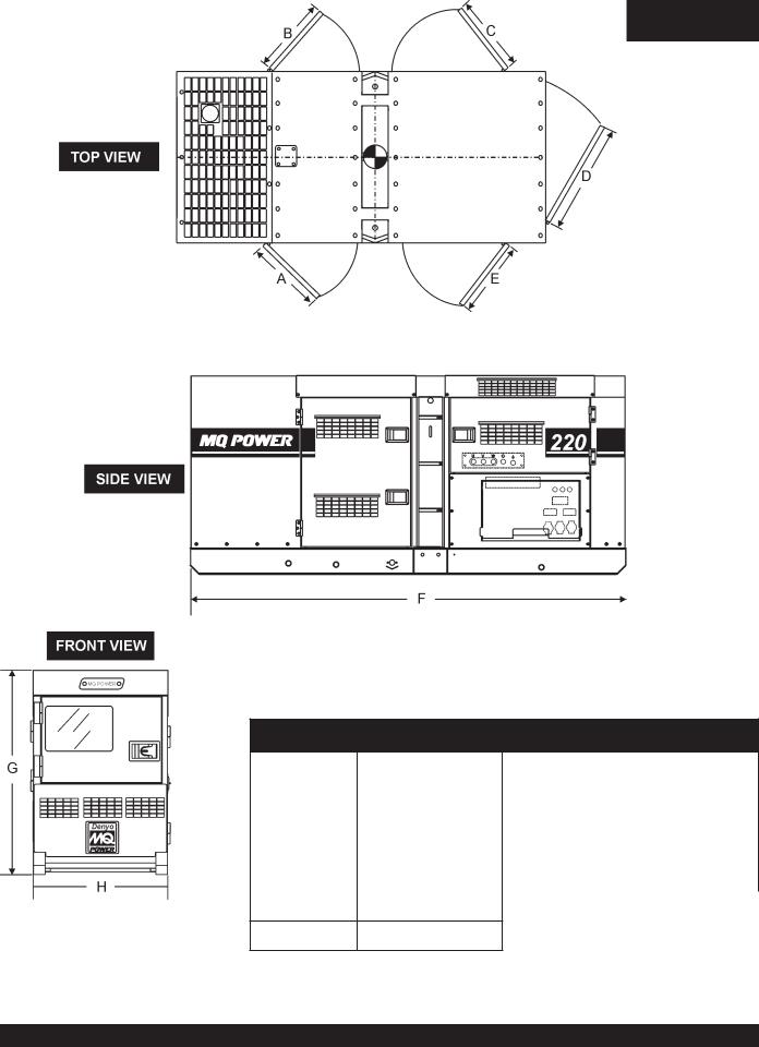
DCA-220SSJ — DIMENSIONS (TOP, SIDE AND FRONT)
TABLE 3. DIMENSIONS
Reference |
Dimension ft. (mm.) |
Reference Letter |
Dimension ft. (mm.) |
|
Letter |
||||
|
|
|
||
|
|
|
|
|
A |
37.00 in. (940 mm.) |
F |
137.80 in. (3,500 mm.) |
|
|
|
|
|
|
B |
37.00 in. (940 mm.) |
G |
66.92 in. (1,700 mm.) |
|
|
|
|
|
|
C |
41.33 in. (1,050 mm.) |
H |
48.81 in. (1,240 mm.) |
|
|
|
|
|
D41.33 in. (1,050 mm.)
E41.33 in. (1,050 mm.)
Figure 1. Dimensions
DCA-220SSJ— OPERATION AND PARTS MANUAL — REV. #1 (03/22/07) — PAGE 7
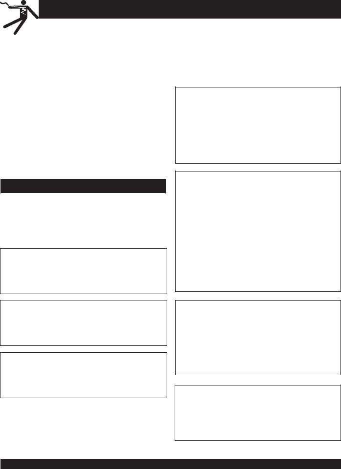
DCA-220SSJ — SAFETY MESSAGE ALERT SYMBOLS
FORYOUR SAFETY AND THE SAFETY OF OTHERS! |
|
HAZARD SYMBOLS |
|
|
|
Safety precautions should be followed at all times when operating this equipment. Failure to read and understand the
Safety Messages and Operating Instructions could result in injury to yourself and others.
|
This Owner's Manual has been |
|
NOTE |
developed to provide complete |
|
instructions for the safe and |
||
|
||
|
efficient operation of the |
|
|
MQ Power Model DCA-220SSJ |
|
|
Whisperwatt™ Generator. |
Before using this generator, ensure that the operating individual has read and understands all instructions in this manual.
SAFETY MESSAGE ALERT SYMBOLS
The three (3) Safety Messages shown below will inform you about potential hazards that could injure you or others. The
Safety Messages specifically address the level of exposure to the operator, and are preceded by one of three words:
DANGER, WARNING, or CAUTION.
DANGER
You WILL be KILLED or SERIOUSLY injured if you do not follow directions.
WARNING
You COULD be KILLED or SERIOUSLY injured if you do not follow directions.
CAUTION
You CAN be injured if you do not follow directions
Potential hazards associated with the operation of this equipment will be referenced with "Hazard Symbols" which appear throughout this manual, and will be referenced in conjunction with Safety "Message Alert Symbols".
WARNING - LETHAL EXHAUST GASES
Gasoline engine exhaust gases contain poisonous carbon monoxide. This gas is colorless and odorless, and can cause DEATH if inhaled. NEVER operate this
equipment in a confined area or enclosed structure that does not provide ample free flow air.
WARNING - EXPLOSIVE FUEL
Gasoline is extremely flammable, and its vapors can cause an explosion if ignited. DO NOT start the engine near spilled fuel or combustible fluids.
DO NOT fill the fuel tank while the engine is running or hot.
DO NOT overfill tank, since spilled fuel could ignite if it comes into contact with hot engine parts or sparks from the ignition system. Store fuel in approved containers, in well-ventilated areas and away from sparks and flames.
NEVER use fuel as a cleaning agent.
WARNING - BURN HAZARDS
Engine components can generate extreme heat.To prevent burns, DO NOT touch these areas while the engine is running or immediately after operations. NEVER operate the engine with heat shields or heat guards removed.
DANGER - ELECTROCUTION HAZARDS
During operation of this generator, there exists the possibility of electrocution, electrical shock or burn, which can cause severe bodily harm or even DEATH!
PAGE 8 — DCA-220SSJ— OPERATION AND PARTS MANUAL — REV. #1 (03/22/07)
DCA-220SSJ — SAFETY MESSAGE ALERT SYMBOLS
WARNING - ROTATING PARTS
NEVER operate equipment with covers, or guards removed. Keep fingers, hands, hair and clothing away from all moving parts to prevent injury.
CAUTION - ACCIDENTAL STARTING
ALWAYS place the MPEC control switch in the OFF/RESET position when the generator is not in use.
CAUTION - OVER-SPEED CONDITIONS
NEVER tamper with the factory settings of the engine governor or settings.
Personal injury and damage to the engine or equipment can result if operating in speed ranges above maximum allowable.
This generator, other property, or the surrounding environment could be damaged if you do not follow instructions.
CAUTION - RESPIRATORY HAZARDS
ALWAYS wear approved respiratory protection.
CAUTION - SIGHT AND HEARING HAZARDS
ALWAYS wear approved eye and hearing protection.
CAUTION - EQUIPMENT DAMAGE MESSAGES
Other important messages are provided throughout this manual to help prevent damage to your generator, other property, or the surrounding environment.
DCA-220SSJ— OPERATION AND PARTS MANUAL — REV. #1 (03/22/07) — PAGE 9
DCA-220SSJ — RULES FOR SAFE OPERATION
DANGER - READTHIS MANUAL!
Failure to follow instructions in this manual may lead to serious injury or even DEATH! This equipment is to be operated by trained and qualified personnel only! This equipment is for industrial use only.
The following safety guidelines should always be used when operating the DCA-220SSJWhisperwatt™ AC Generator.
General Safety:
■DO NOT operate or service this equipment before reading this entire manual.
The operator MUST BE familiar with proper safety precautions and operations techniques before using generator.
■This equipment should not be operated by persons under
18 years of age.
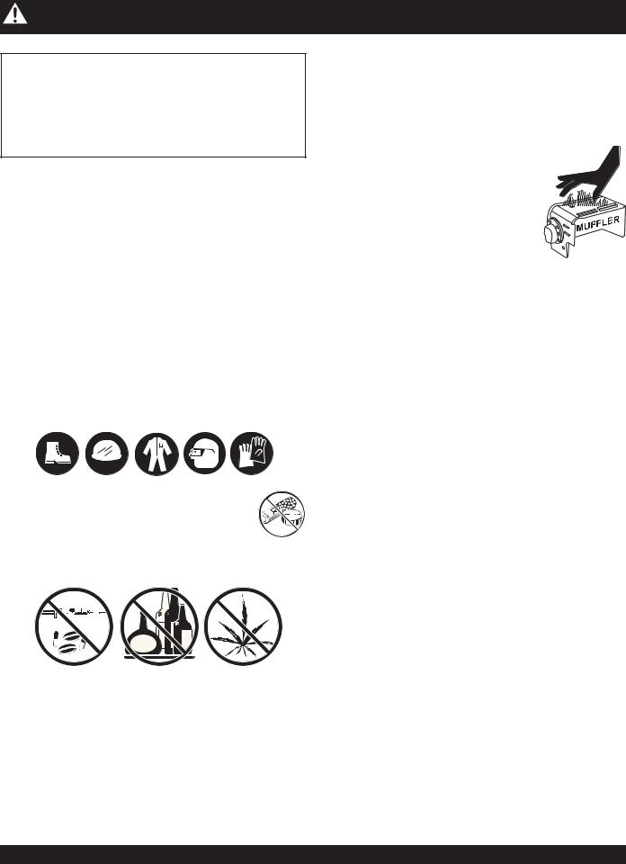
■NEVER operate this equipment without proper protective clothing, shatterproof glasses, steel-toed boots and other protective devices required by the job.
■ NEVER operate this equipment when not feeling well due to fatigue, illness or taking medicine.
■NEVER operate this equipment under the influence or drugs or alcohol.
■NEVER use accessories or attachments, which are not recommended by MQ Power for this equipment. Damage to the equipment and/or injury to user may result.
■Manufacturer does not assume responsibility for any accident due to equipment modifications. Unauthorized equipment modification will void all warranties.
■Whenever necessary, replace nameplate, operation and safety decals when they become difficult read.
■ALWAYS check the machine for loosened threads or bolts before starting.
■NEVER operate the generator in an explosive atmosphere or near combustible materials. An explosion or fire could result causing severe bodily harm or even death.
■NEVER touch the hot exhaust manifold, muffler or cylinder. Allow these parts to cool before servicing engine or generator.
■HighTemperatures – Allow the engine
to cool before performing service and maintenance functions. Contact with hot! components can cause serious burns.
■The engine of this generator requires an adequate free flow of cooling air. NEVER operate the generator in any enclosed or narrow area where free flow of the air is restricted. If the air flow is
restricted it will cause serious damage to the generator or engine and may cause injury to people. The generator engine gives off DEADLY carbon monoxide gas.
■DO NOT place hands or fingers inside generator engine compartment when engine is running.
■NEVER run engine without air filter.Severe engine damage may occur.
■DO NOT leave the generator running in the manual mode unattended.
■Refer to the John Deere Engine Owner's Manual for engine technical questions or information.
■ALWAYS store equipment properly when it is not being used. Equipment should be stored in a clean, dry location out of the reach of children.
PAGE 10 — DCA-220SSJ— OPERATION AND PARTS MANUAL — REV. #1 (03/22/07)
DCA-220SSJ — RULES FOR SAFE OPERATION
Generator Grounding
To guard against electrical shock and possible damage to the equipment, it is important to provide a good EARTH ground.
Article 250 (Grounding) of the National Electrical Code (NEC) provides guide lines for proper grounding and specifies that the cable ground shall be connected to the grounding system of the building as close to the point of cable entry as practical.
The following safety recommendations should also be followed:
■ALWAYS make sure generator is properly grounded.
■NEVER use gas piping as an electrical ground.
■ALWAYS make sure that electrical circuits are properly grounded per the National Electrical Code (NEC) and local codes before operating generator. Severe injury or
DEATH! by electrocution can result from operating an ungrounded generator.
■ALWAYS be sure to use the ground terminal (green wire) when connecting a load to the U,V, and W output terminal lugs.
Electrical Safety
■ALWAYS have a qualified electrician perform the generator wiring installation.
■ALWAYS make sure generator installation is accordance with the National Electrical Code (NEC) and local codes before operating generator.
■NEVER use a defective or frayed power cable. Check the cable for cuts in the insulation.
■NEVER use a extension cord that is frayed or damaged where the insulation has been cut.
■ALWAYS make certain that proper extension cord has been selected for the job. See Table 6.
■NEVER power cables or cords lay in water.
■NEVER stand in waterwhile AC power from the generator is being transfer to a load.
DANGER - ELECTROCUTION HAZARDS
During operation of this generator, there exists the possibility of electrocution, electrical shock or burn, which can cause severe bodily harm or even DEATH!
To avoid these hazards:
NEVER use damaged or worn cables when connecting equipment to the generator. Make sure power connecting cables are securely connected to the generator’s output terminals, insufficient tightening of the terminal connections may cause damage to the generator
and electrical shock.
NEVER grab or touch a live power cord with wet hands.
NEVER touch output terminals during operation. This is extremely dangerous. ALWAYS stop the machine and place the circuit breaker in the OFF position when contact with the output terminals is required.
Backfeed to a utility system can cause electrocution and or property damage. DO NOT connect to any building's electrical system except through an approved device or after building main switch is opened.
ALWAYS have a licensed electrician perform the installation
POWER
CORD
(POWER ON)
DCA-220SSJ— OPERATION AND PARTS MANUAL — REV. #1 (03/22/07) — PAGE 11

DCA-220SSJ — RULES FOR SAFE OPERATION
Maintenance Safety
■The electrical voltage required to operate the generator can cause severe injury or even death through physical contact with live circuits. Turn all circuit breakers OFF before performing maintenance on the generator.
■NEVER lubricate components or attempt service on a running machine.
■ALWAYS disconnect the NEGATIVE battery terminal before performing service on the generator.
■Follow all Battery Safety Guidelines listed in this manual when handleing or servicing the generator.
■ALWAYS allow the machine a proper amount of time to cool before servicing.
■Keep the machinery in proper running condition.
■Fix damage to the machine immediately and always replace broken parts.
■ALWAYS service air cleaner frequently to prevent engine malfunction.
WARNING - BURN HAZARDS
To prevent burns, DO NOT touch or open any of the below mentioned components while the engine is
running or immediately after operations.
Always allow sufficient time for the engine and generator to cool before performing maintenance.
■Radiator Cap - Removing the radiator cap while the engine is hot will result in high pressurized, boiling water to gush out of the radiator, causing severe scalding to any persons in the general area of the generator.
■Coolant Drain Plug - Removing the coolant drain plug while the engine is hot will result in hot coolant gushing out of the coolant drain plug, therefore causing severe scalding to any persons in the general area of the generator.
■Engine Oil Drain Plug - Removing the engine oil drain plug while the engine is hot will result in hot oil gushing out of the oil drain plug, therefore causing severe scalding to any persons in the general area of the generator.
Battery Safety
Use the following guidelines when handling the battery:
■The battery contains acids that can cause injury to the eyes and skin. To avoid eye irritation, always wear safety glasses.
■Use well insulated gloves when picking up the battery.
DANGER - EXPLOSION HAZARDS
The risk of an explosion exists when performing service on the battery. To avoid severe injury or DEATH:
■DO NOT drop the battery.There is the possibility of risk that the battery may explode.
■DO NOT expose the battery to open flames, sparks, cigarettes
etc.The battery contains combustible gases and liquids.
If these gases and liquids come in contact with a flame or spark, an explosion could occur.
■ALWAYS keep the battery charged. If the battery is not charged a buildup of combustible gas will occur.
■ALWAYS keepbatterychargingandcablesin good working condition. Repair or replace all worn cables.
■ALWAYS recharge the battery in an vented air environment, to avoid risk of a dangerous concentration of combustible gases.
■In case the battery liquid (dilute sulfuric acid) comes in contact with clothing or skin, rinse skin or clothing immediately with plenty of water.
■In case the battery liquid (dilute sulfuric acid) comes in contact with your EYES, rinse eyes immediately with plenty of water and contact the nearest doctor or hospital to seek medical attention.
PAGE 12 — DCA-220SSJ— OPERATION AND PARTS MANUAL — REV. #1 (03/22/07)
DCA-220SSJ — RULES FOR SAFE OPERATION
Towing &Transporting Safety
To reduce the possibility of an accident while transporting the generator on public roads, always make sure the trailer that supports the generator and the towing vehicle are in good operating condition and both units are mechanically sound.
The following list of safety precautions should be followed when towing your generator:
CAUTION - FOLLOWTOWING REGULATIONS
Check with your local county or state safety towing regulations, in addition to meeting Department of Transportation (DOT) SafetyTowing Regulations, before towing your generator.
■ALWAYS shutdown engine before transporting.
■Tighten both fuel tank caps securely.
■If generator is mounted on a trailer, make sure trailer complies with all local and state safety transportation laws. Follow the listed Towing & Transporting Safety guidelines for basic towing techniques.
■Make sure the hitch and coupling of the towing vehicle are rated equal to, or greater than the trailer "gross vehicle weight rating.”
■ALWAYS inspect the hitch and coupling for wear. NEVER tow a trailer with defective hitches, couplings, chains etc.
■Check the tire air pressure on both towing vehicle and trailer. Trailer tires should be inflated to 50 psi cold.
Also check the tire tread wear on both vehicles.
■ALWAYS make sure the trailer is equipped with a "Safety Chain".
■ALWAYS attach trailer’s safety chains to towing vehicle properly.
■ALWAYS make sure the vehicle and trailer directional, backup, brake, and trailer lights are connected and working properly.
■DOT Requirements include the following:
z Connect and test electric brake operation.
z Secure portable power cables in cable tray with tie wraps.
■The maximum speed for highway towing is 55 MPH unless posted otherwise. Recommended off-road towing is not to exceed 15 MPH or less depending on type of terrain.
■Place chock blocks underneath wheel to prevent rolling, while parked.
■Use the trailer’s swivel jack to adjust the trailer height to a level position while parked.
■Avoid sudden stops and starts. This can cause skidding, or jack-knifing. Smooth, gradual starts and stops will improve towing.
■Avoid sharp turns.
■Trailer should be adjusted to a level position at all times when towing.
■Raise and lock trailer wheel stand in up position when transporting.
■The maximum speed for highway towing is 55 MPH unless posted otherwise. Recommended off-road towing is not to exceed 15 MPH or less depending on type of terrain.
■Place support blocks underneath the trailer’s bumper to prevent tipping, while parked.
■Avoid sharp turns to prevent rolling.
■DO NOT transport generator with fuel in tank.
Emergencies
■ALWAYS know the location of the nearest fire extinguisher.
■ALWAYS know the location of the nearest and first aid kit.
■ALWAYS know the location of the nearest phone or keep a phone on the job site, in case of emergencies.
■ALWAYS have easy access to the phone numbers of the nearest Ambulance, Doctor and Fire Department. This information will be invaluable in the case of an emergency.
DCA-220SSJ— OPERATION AND PARTS MANUAL — REV. #1 (03/22/07) — PAGE 13
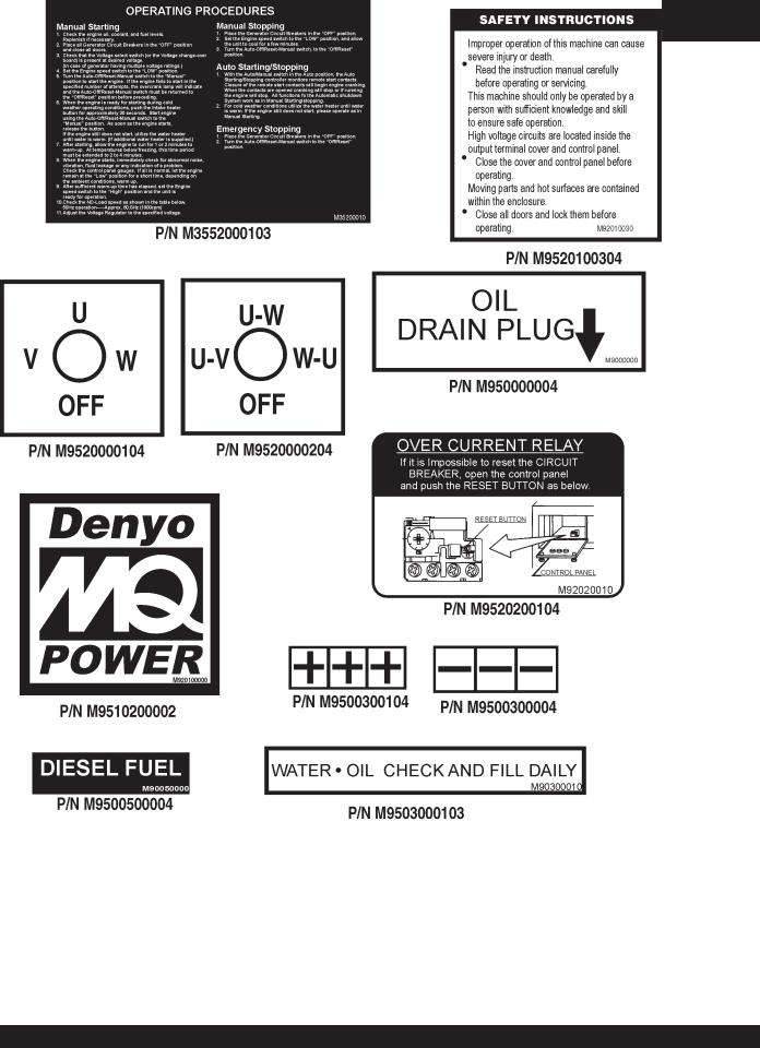
DCA-220SSJ — GENERATOR DECALS
The DCA-220SSJ generator is equipped with a number of safety decals (Figures 2 & 3). These decals are provided for operator safety and maintenance information. The illustration below and on the preceding page show the decals as they appear on the machine. Should any of these decals become unreadable, replacements can be obtained from your dealer.
Figure 2. Generator Decals
PAGE 14 — DCA-220SSJ— OPERATION AND PARTS MANUAL — REV. #1 (03/22/07)

DCA-220SSJ — GENERATOR DECALS
Figure 3. Generator Decals (Cont inued)
DCA-220SSJ— OPERATION AND PARTS MANUAL — REV. #1 (03/22/07) — PAGE 15
DCA-220SSJ — INSTALLATION
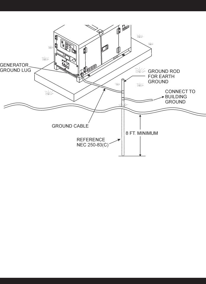
Figure 4.Typical Generator Grounding Application
PAGE 16 — DCA-220SSJ— OPERATION AND PARTS MANUAL — REV. #1 (03/22/07)
Outdoor Installation
Install the generator in a area that is free of debris, bystanders, and overhead obstructions. Make sure the generator is on secure level ground so that it cannot slide or shift around. Also install the generator in a manner so that the exhaust will not be discharged in the direction of nearby homes.
The installation site must be relatively free from moisture and dust. All electrical equipment should be protected from excessive moisture. Failure to do will result in deterioration of the insulation and will result in short circuits and grounding.
Foreign materials such as dust, sand, lint and abrasive materials have a tendency to cause excessive wear to engine and alternator parts.
CAUTION - EXHAUST HAZARD
Pay close attention to ventilation when operating the generator inside tunnels and caves. The engine exhaust contains noxious elements. Engine exhaust must be routed to a ventilated area.
Indoor Installation
Exhaust gases from diesel engines are extremely poisonous.
Whenever an engine is installed indoors the exhaust fumes must be vented to the outside.The engine should be installed at least two feet from any outside wall. Using an exhaust pipe which is too long or too small can cause excessive back pressure which will cause the engine to heat excessively and possibly burn the valves.
Mounting
The generator must be mounted on a solid foundation (such as concrete) and set firmly on the foundation to isolate vibration of the generator when it is running. The generator must set at least 6 inches above the floor or grade level (in accordance to NFPA 110, Chapter 5-4.1). DO NOT remove the metal skids on the bottom of the generator. They are to resist damage to the bottom of the generator and to maintain alignment.
DCA-220SSJ — INSTALLATION
Generator Grounding
To guard against electrical shock and possible damage to the equipment, it is important to provide a good EARTH ground.
Article 250 (Grounding) of the National Electrical Code (NEC) provides guide lines for proper grounding and specifies that the cable ground shall be connected to the grounding system of the building as close to the point of cable entry as practical.
NEC articles 250-64(b) and 250-66 set the following grounding requirements:
1.Use one of the following wire types to connect the generator to earth ground.
a.Copper - 10 AWG (5.3 mm2) or larger.
b.Aluminum - 8 AWG (8.4 mm2) or larger.
2.When grounding the generator (Figure 4) connect the ground cable between the lock washer and the nut on the generator and tighten the nut fully. Connect the other end of the ground cable to earth ground.
3.NEC article 250-52(c) specifies that the earth ground rod should be buried aminimum of 8 ft. into the ground.
When connecting the generator NOTE to any buildings electrical system ALWAYS consult with
a licensed electrician.
DCA-220SSJ— OPERATION AND PARTS MANUAL — REV. #1 (03/22/07) — PAGE 17

DCA-220SSJ — GENERAL INFORMATION
DCA-220SSJWhisperwatt™ Series Familiarization
Generator
The MQ Power Model DCA-220SSJ is a 176 kW generator
(Figure 5) that is designed as a high quality portable (requires a trailer for transport) power source for telecom sites, lighting facilities, power tools, submersible pumps and other industrial and construction machinery.
Engine Operating Panel
The “Engine Operating Panel” is provided with the following:
■Tachometer
■Water Temperature Gauge
■Oil Pressure Gauge
■Charging Ammeter Gauge
■Fuel Level Gauge
■Engine Speed Switch
■Panel Light/Panel Light Switch
■Auto ON/OFF Engine Controller (MPEC)
■Preheat Lamp
■Warning Lamp
■Emergency Stop Lamp
■Emergency Stop Button
Generator Control Panel
The “Generator Control Panel” is provided with the following:
■Frequency Meter (Hz)
■AC Ammeter (Amps)
■AC Voltmeter (Volts)
■Ammeter Change-Over Switch
■Voltmeter Change-Over Switch
■Voltage Regulator
■3-Pole, 600 amp Main Circuit Breaker
■“Control Box” (located behind the Gen. Control Panel)
■Automatic Voltage Regulator
■Diagnostic Display
■Current Transformer
■Over-Current Relay
■Voltage Rectifer
■Starter Relay
■Engine Controller (Computer Controlled)
■Voltage Change-over Board
Output Terminal Panel
The “Output Terminal Panel” is provided with the following:
■Three 120/240V output receptacles (CS-6369), 50A
■Three auxilliary circuit breakers, 50A
■Two 120V output receptacles (GFCI), 20A
■Two GFCI circuit breakers, 20A
■Five output terminal lugs (3Ø power)
■Battery Charger (Optional)
■Water Heater (Optional)
Open Delta Excitation System
The DCA-220SSJ generator is equipped with the state of the art "Open-Delta" excitation system. The open delta system consist of an electrically independent winding wound among stationary windings of the AC output section.
There are four connections of the open delta A, B, C and D.
During steady state loads, the power from the voltage regulator is supplied from the parallel connections of A to B, A to D, and C to D. These three phases of the voltage input to the voltage regulator are then rectified and are the excitation current for the exciter section.
When a heavy load, such as a motor starting or a short circuit occurs, the automatic voltage regulator (AVR) switches the configuration of the open delta to the series connection of B to C.This has the effect of adding the voltages of each phase to provide higher excitation to the exciter section and thus better voltage response during the application of heavy loads.
The connections of the AVR to the AC output windings are for sensing only. No power is required from these windings.
The open-delta design provides virtually unlimited excitation current, offering maximum motor starting capabilities. The excitation does not have a "fixed ceiling" and responds according the demands of the required load.
Engine
The DCA-220SSJ is powered by a 6 cylinder, water cooled, direct injection, turbocharged John Deere 6068HF485Turbo Diesel Engine. This engine is designed to meet every performance requirement for the generator. Reference Table 1 for engine specifications.
In keeping with MQ Power's policy of constantly improving its products, the specifications quoted herein are subject to change without prior notice.
Electric Governor System
The electric governor system controls the RPMs of the engine. When the engine demand increases or decreases, the governor system regulates the frequency variation to ±.25%.
Extension Cables
When electric power is to be provided to various tools or loads at some distance from the generator, extension cords are normally used. Cables should be sized to allow for distance in length and amperage so that the voltage drop between the generator and point of use (load) is held to a minimum. Use the cable selection chart (Table 6) as a guide for selecting proper extension cable size.
PAGE 18 — DCA-220SSJ— OPERATION AND PARTS MANUAL — REV. #1 (03/22/07)
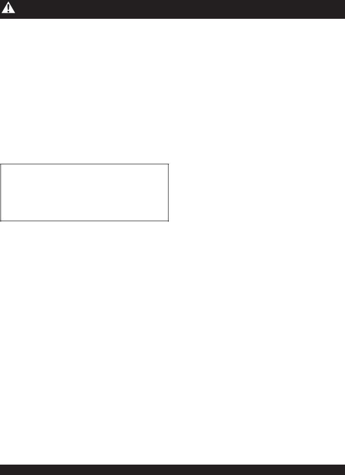
DCA-220SSJ — MAJOR COMPONENTS
Table 4. Generator Major Components
ITEM NO. |
DESCRIPTION |
|
|
1 |
Output Terminal Panel Assembly |
|
|
2 |
Output Receptacles Assembly |
|
|
3 |
Air Filter Assembly |
|
|
4 |
Muffler Assembly |
|
|
5 |
Fuel Tank Assembly |
|
|
6 |
Engine Assembly |
|
|
7 |
Battery Assembly |
|
|
8 |
Generator Assembly |
|
|
9 |
Circuit Breaker Assembly |
|
|
10 |
Diagnostic Display Assembly |
|
|
11 |
Generator/Engine Control Panel Assembly |
|
|
DCA-220SSJ— OPERATION AND PARTS MANUAL — REV. #1 (03/22/07) — PAGE 19
DCA-220SSJ — DIAGNOSTIC DISPLAY
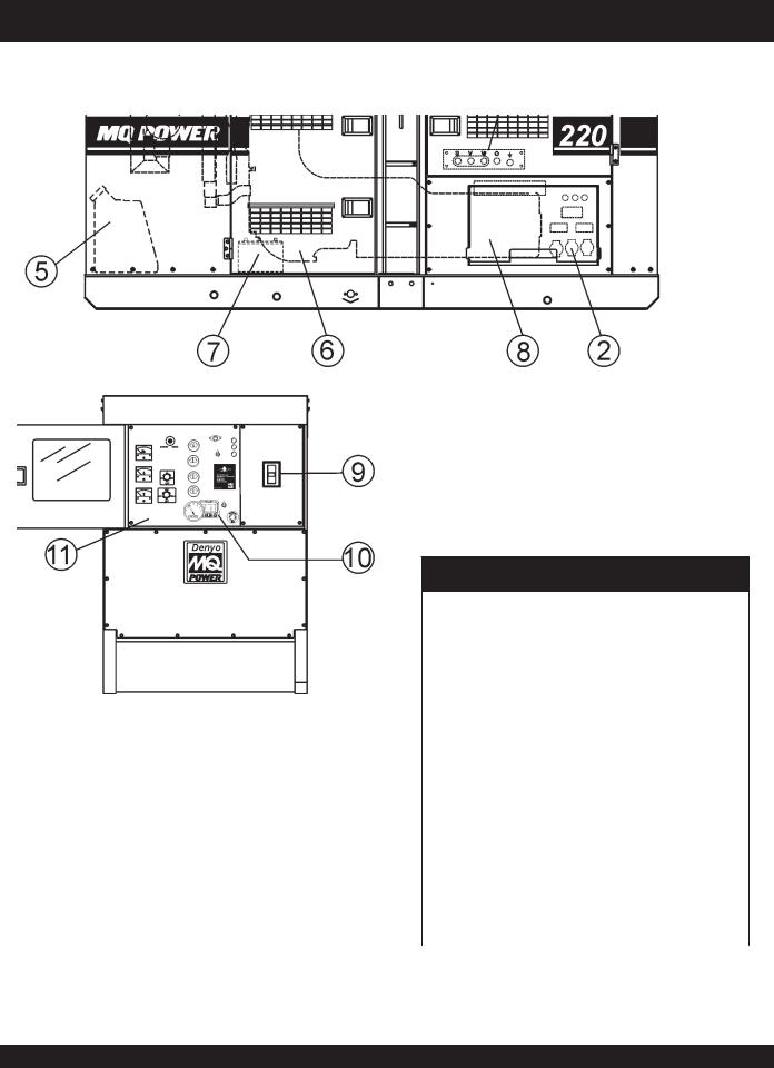
Figure 6. Diagnostic Display Panel
The diagnostic display panel located inside the control box on the generator (Figure 6) is designed to meet the needs for instrumentation and control of electronically controlled engine communication using the SAEJ1939 Controller Area Network (CAN). This diagnostic display is a multifunction tool that enables equipment operators to view many different engine parameters and service codes.
The keypad on the diagnostic display panel is a capacitive touch sensing system.There are no mechanical switches to wear or stick. This keypad (display unit) will operate in extreme hot or cold weather conditions.
Other components in the system are microprocessor-based components for displaying critical engine data broadcast by an electronic engine or transmission’s Engine Control Unit
(ECU): engine RPM, oil pressure, coolant temperature, system voltage, etc., and a combination audible alarm and relay unit for warning and shutdown annunciation.
The Engine Control Unit (ECU) used with this generator diagnosis engine faults that arise with the the engine control system and the engine itself. Engine faults can be determined by viewing the DiagnosticTrouble Codes (Active Fault Codes) which are displayed on the Diagnostic Display Panel. See the John Deere Engine Operator’s Manual for a complete listing of active fault codes and countermeasures.
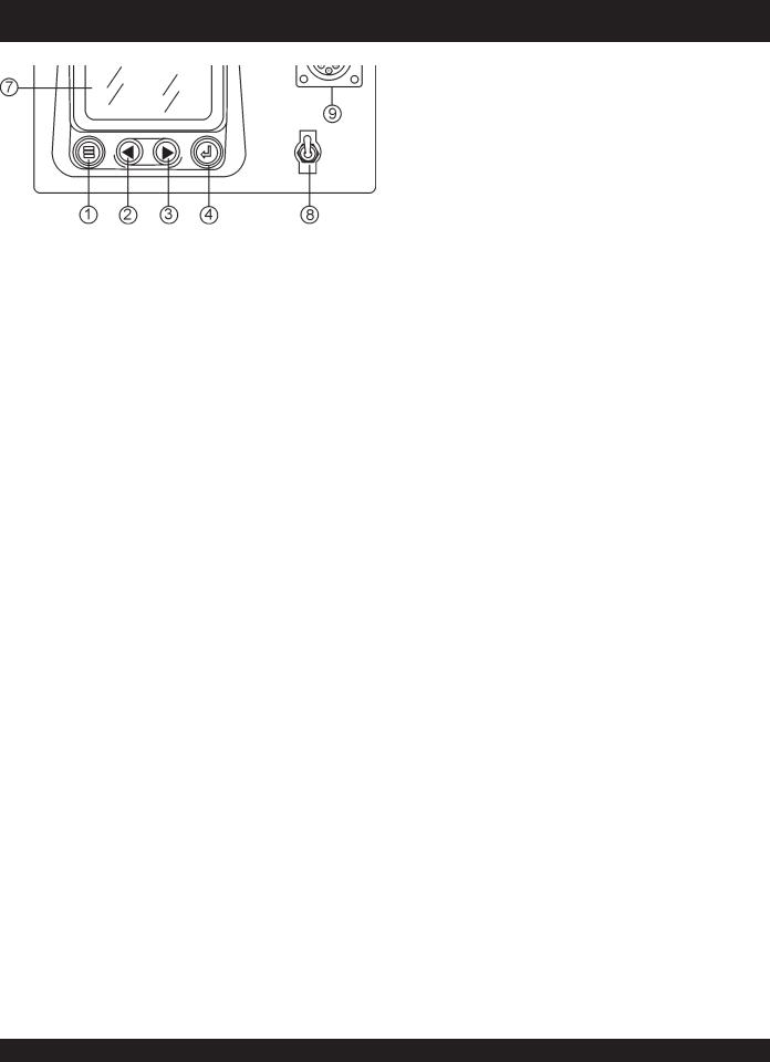
The following definitions describe the controls and functions of the Diagnostic Display Panel (Figure 6).
1.Menu Button – Press this button to enter or exit menu screens.
2.Left Arrow Button– Press this button to scroll through the screen either moving the parameter selection toward the left or upward.
3.Right Arrow Button – Press this button to scroll through the screen either moving the parameter selection toward the right or downward.
4.Enter Key Button – Press this button to select the parameter that is highlighted on the screen.
5.Emergency Stop LED – When lit (RED) indicates a major fault has occured. This condition will shudown the generator.
6.Warning LED – When lit (AMBER), indicates a engine parameter has exceeded its limits (minor fault). The generator will still run in this condition.
7.Display Screen – Graphical backlight LCD screen. Back lighting is controlled via menu or external dimmer potentiometer. The display can show either a single parameter or a quadrant display showing four parameters simultaneously.
8.Diagnostic Switch – When placed in the ON position, will activate the diagnostic display panel.
9.CAN Diagnostic Connector – Controller Area Network connector. This connector outputs diagnostic error codes. Connect a scanner or similar device into this connector to read error codes.
Display Parameters
The following are some of the engine and transmission parameters displayed on the diagnostic disply panel.
■Engine RPM’s
■Engine Hours
■System Voltage
■% Engine Load at current RPM
■CoolantTemperature
■Oil Pressure
■Fuel Economy
■Current Fuel Consumption
■Throttle Position
■Engine Manifold Air Temperature
■Active Service Codes
■Set Units for Display (English or Metric)
■English Configuration Parameters.
PAGE 20 — DCA-220SSJ— OPERATION AND PARTS MANUAL — REV. #1 (03/22/07)
DCA-220SSJ — DIAGNOSTIC DISPLAY
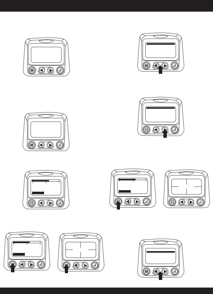
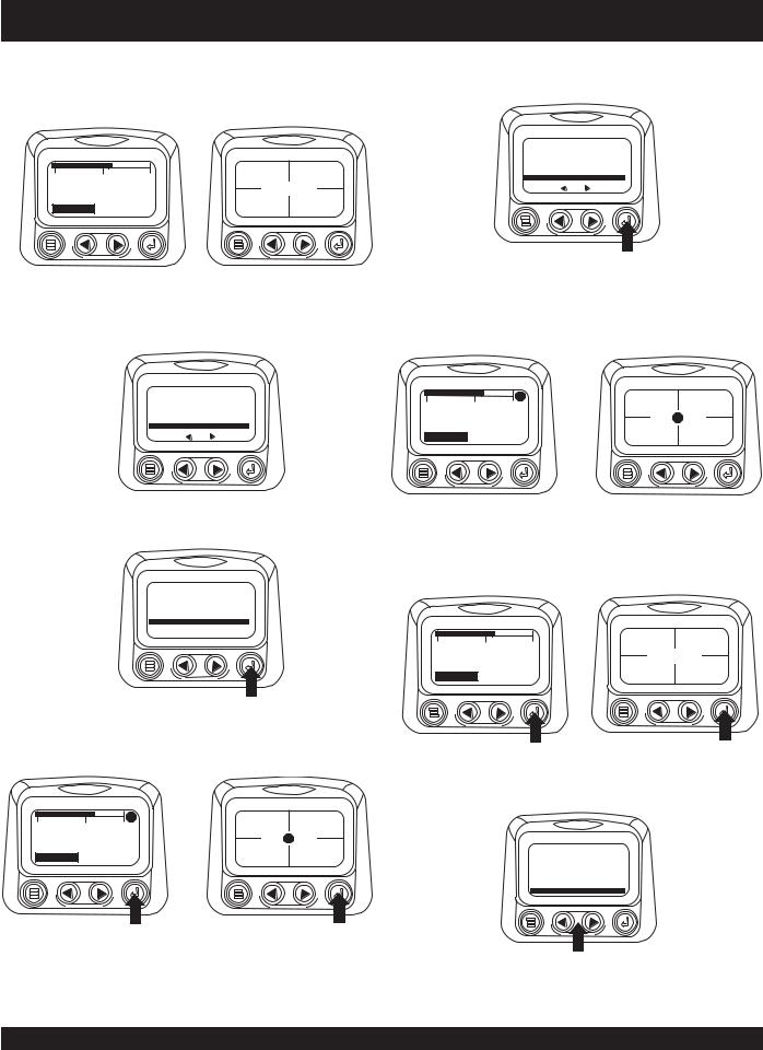
First Time Start Up
1.When power is first applied to the diagnostic display, the “Logo” is displayed.
2.The first seven items of the “Main Menu” will be displayed.Touching the“Arrow Buttons”will scroll through the menu selection.
GO TO 1-UP DISPLAY
LANGUAGES
STORED CODES
ENGINE CONFG
SETUP 1-UP DISPLAY
SETUP-4-UP DISPLAY
SELECT UNITS
2. The “Wait to Start” message will be displayed for |
3. Touching the right arrow button will scroll down to reveal |
|
engines with a pre-startup sequence. Once the “Wait to |
the last items of “Main Menu” screen highlighting the |
|
next item down. |
||
Start” message is no longer displayed the operator may |
||
|
||
start the engine. Note: Displays only when SAE J1939 |
|
message is supported by engine manufacturer.
ADJUST BACKLIGHT
ADJUST CONTRAST
UTILITIES
WAIT TO
START
PREHEAT
3. Once the engine has started the single engine parameter is displayed.
4. Touch the Arrows” to scroll to the desired menu item or touch “Menu” to exit the Main menu and return to the engine parameter display.
0 |
1500 |
3000 |
1800 RPM
ENG RPM COOL TEMP
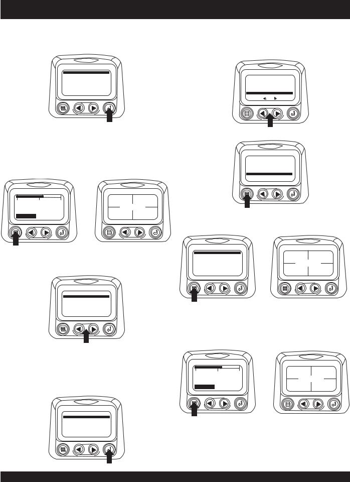
Main Menu Navigation
1.Starting at the single or four engine parameter display, touch “Menu”.
0 |
1500 |
3000 |
98% |
1000 RPM |
|
1800 RPM |
LOAD RPM |
ENG RPM |
|
|
|
|
||
ENG RPM COOL TEMP |
14.2 |
57 PSI |
||
BATT VOLT |
OIL PRES |
|||
Selecting a Language
1.Starting at the main menu display use the “Arrows to scroll to the “Language” menu and once highlighted touch the “Enter” button.
0 |
1500 |
3000 |
98% |
1000 RPM |
|
1800 RPM |
LOAD RPM |
ENG RPM |
|
|
|
|
||
ENG RPM COOL TEMP |
14.2 |
57 PSI |
||
BATT VOLT |
OIL PRES |
|||
GO TO 1-UP DISPLAY
LANGUAGES
STORED CODES
ENGINE CONFG SETUP 1-UP DISPLAY SETUP-4-UP DISPLAY SELECT UNITS
DCA-220SSJ— OPERATION AND PARTS MANUAL — REV. #1 (03/22/07) — PAGE 21

DCA-220SSJ — DIAGNOSTIC DISPLAY
2. The language choices will be displayed. Use the “Arrow” 4. |
If the word “MORE” appears above the “Arrow Buttons” |
buttons to scroll through the selections and touch “Enter” |
there are more stored fault codes that may be viewed. |
to make a selection. |
Use the “Arrow Buttons” to scroll to the next Stored |
|
Diagnostic Code. |
ENGLISH
ESPANOL
FRANCAIS |
1 of x |
|
|
|
|
DEUTSCH |
|
|
|
SPN110 FMI10 |
|
|
HIGH COOLANT TEMP |
|
|
MORE |
HIDE |
3.Now that you have selected the language, touch the “Menu” button to return to the main menu display.
Stored Fault Codes
1.Starting at the single or the four engine parameter display touch the “Menu button”.
|
|
|
98% |
1000 RPM |
0 |
1500 |
3000 |
LOAD RPM |
ENG RPM |
|
1800 RPM |
|
|
|
|
|
|
14.2 |
57 PSI |
ENG RPM COOL TEMP |
BATT VOLT |
OIL PRES |
||
|
|
|||
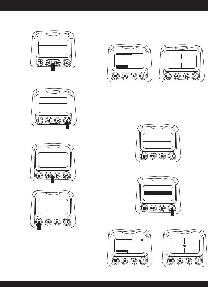
2. The main menu will pop up on the display.Use the “Arrow Buttons” to scroll through the menu until the Stored Fault Codes is highlighted.
GO TO 1-UP DISPLAY
STORED CODES
ENGINE CONFG
SETUP 1-UP DISPLAY
SETUP-4-UP DISPLAY
SELECT UNITS
ADJUST BACKLIGHT
3.Once the “Stored Fault Codes” menu item has been highlighted touch the “Enter Button” to view the “Stored Fault Codes” (when applicable, consult engine or transmission manufacturer for SAE J1939 supported parameters).
GO TO 1-UP DISPLAY
STORED CODES
ENGINE CONFG
SETUP 1-UP DISPLAY
SETUP-4-UP DISPLAY
SELECT UNITS
ADJUST BACKLIGHT
5.Touch the “Menu Button to return to the main menu.
1 of x
SPN110 FMI10
HIGH COOLANT TEMP
 MORE
MORE HIDE
HIDE
6.Touch the “Menu Button” to exit the Main menu and return to the engine parameter display.
GO TO 1-UP DISPLAY |
98% |
1000 RPM |
|
STORED CODES |
|||
LOAD RPM |
ENG RPM |
||
ENGINE CONFG |
|
|
|
SETUP 1-UP DISPLAY |
|
|
|
SETUP-4-UP DISPLAY |
14.2 |
57 PSI |
|
SELECT UNITS |
|||
ADJUST BACKLIGHT |
BATT VOLT |
OIL PRES |
|
|
|
Engine Configuration Data
1.Starting at the single or four engine parameter display touch the “Menu Button”.
0 |
1500 |
3000 |
98% |
1000 RPM |
|
1800 RPM |
LOAD RPM |
ENG RPM |
|
|
|
|
||
ENG RPM COOL TEMP |
14.2 |
57 PSI |
||
BATT VOLT |
OIL PRES |
|||
PAGE 22 — DCA-220SSJ— OPERATION AND PARTS MANUAL — REV. #1 (03/22/07)
DCA-220SSJ — DIAGNOSTIC DISPLAY
First Time Start Up
1.When power is first applied to the diagnostic display, the “Logo” is displayed.
2.The first seven items of the “Main Menu” will be displayed.Touching the“Arrow Buttons”will scroll through the menu selection.
GO TO 1-UP DISPLAY
LANGUAGES
STORED CODES
ENGINE CONFG
SETUP 1-UP DISPLAY
SETUP-4-UP DISPLAY
SELECT UNITS
2. The “Wait to Start” message will be displayed for |
3. Touching the right arrow button will scroll down to reveal |
|
engines with a pre-startup sequence. Once the “Wait to |
the last items of “Main Menu” screen highlighting the |
|
next item down. |
||
Start” message is no longer displayed the operator may |
||
|
||
start the engine. Note: Displays only when SAE J1939 |
|
message is supported by engine manufacturer.
ADJUST BACKLIGHT
ADJUST CONTRAST
UTILITIES
WAIT TO
START
PREHEAT
3. Once the engine has started the single engine parameter is displayed.
4. Touch the Arrows” to scroll to the desired menu item or touch “Menu” to exit the Main menu and return to the engine parameter display.
0 |
1500 |
3000 |
1800 RPM
ENG RPM COOL TEMP
Main Menu Navigation
1.Starting at the single or four engine parameter display, touch “Menu”.
0 |
1500 |
3000 |
98% |
1000 RPM |
|
1800 RPM |
LOAD RPM |
ENG RPM |
|
|
|
|
||
ENG RPM COOL TEMP |
14.2 |
57 PSI |
||
BATT VOLT |
OIL PRES |
|||
Selecting a Language
1.Starting at the main menu display use the “Arrows to scroll to the “Language” menu and once highlighted touch the “Enter” button.
0 |
1500 |
3000 |
98% |
1000 RPM |
|
1800 RPM |
LOAD RPM |
ENG RPM |
|
|
|
|
||
ENG RPM COOL TEMP |
14.2 |
57 PSI |
||
BATT VOLT |
OIL PRES |
|||
GO TO 1-UP DISPLAY
LANGUAGES
STORED CODES
ENGINE CONFG SETUP 1-UP DISPLAY SETUP-4-UP DISPLAY SELECT UNITS
DCA-220SSJ— OPERATION AND PARTS MANUAL — REV. #1 (03/22/07) — PAGE 23
DCA-220SSJ — DIAGNOSTIC DISPLAY
2. The language choices will be displayed. Use the “Arrow” 4. |
If the word “MORE” appears above the “Arrow Buttons” |
buttons to scroll through the selections and touch “Enter” |
there are more stored fault codes that may be viewed. |
to make a selection. |
Use the “Arrow Buttons” to scroll to the next Stored |
|
Diagnostic Code. |
ENGLISH
ESPANOL
FRANCAIS |
1 of x |
|
|
|
|
DEUTSCH |
|
|
|
SPN110 FMI10 |
|
|
HIGH COOLANT TEMP |
|
|
MORE |
HIDE |
3.Now that you have selected the language, touch the “Menu” button to return to the main menu display.
Stored Fault Codes
1.Starting at the single or the four engine parameter display touch the “Menu button”.
|
|
|
98% |
1000 RPM |
0 |
1500 |
3000 |
LOAD RPM |
ENG RPM |
|
1800 RPM |
|
|
|
|
|
|
14.2 |
57 PSI |
ENG RPM COOL TEMP |
BATT VOLT |
OIL PRES |
||
|
|
|||
2. The main menu will pop up on the display.Use the “Arrow Buttons” to scroll through the menu until the Stored Fault Codes is highlighted.
GO TO 1-UP DISPLAY
STORED CODES
ENGINE CONFG
SETUP 1-UP DISPLAY
SETUP-4-UP DISPLAY
SELECT UNITS
ADJUST BACKLIGHT
3.Once the “Stored Fault Codes” menu item has been highlighted touch the “Enter Button” to view the “Stored Fault Codes” (when applicable, consult engine or transmission manufacturer for SAE J1939 supported parameters).
GO TO 1-UP DISPLAY
STORED CODES
ENGINE CONFG
SETUP 1-UP DISPLAY
SETUP-4-UP DISPLAY
SELECT UNITS
ADJUST BACKLIGHT
5.Touch the “Menu Button to return to the main menu.
1 of x
SPN110 FMI10
HIGH COOLANT TEMP
 MORE
MORE HIDE
HIDE
6.Touch the “Menu Button” to exit the Main menu and return to the engine parameter display.
GO TO 1-UP DISPLAY |
98% |
1000 RPM |
|
STORED CODES |
|||
LOAD RPM |
ENG RPM |
||
ENGINE CONFG |
|
|
|
SETUP 1-UP DISPLAY |
|
|
|
SETUP-4-UP DISPLAY |
14.2 |
57 PSI |
|
SELECT UNITS |
|||
ADJUST BACKLIGHT |
BATT VOLT |
OIL PRES |
|
|
|
Engine Configuration Data
1.Starting at the single or four engine parameter display touch the “Menu Button”.
0 |
1500 |
3000 |
98% |
1000 RPM |
|
1800 RPM |
LOAD RPM |
ENG RPM |
|
|
|
|
||
ENG RPM COOL TEMP |
14.2 |
57 PSI |
||
BATT VOLT |
OIL PRES |
|||
PAGE 24 — DCA-220SSJ— OPERATION AND PARTS MANUAL — REV. #1 (03/22/07)
DCA-220SSJ — DIAGNOSTIC DISPLAY
2.The main menu will pop up on the display.Use the “Arrow Buttons” to scroll through the menu until the “Engine Configuration” menu item has been highlighted.
GO TO 1-UP DISPLAY
STORED CODES
ENGINE CONFG
SETUP 1-UP DISPLAY
SETUP-4-UP DISPLAY
SELECT UNITS
ADJUST BACKLIGHT
3.Once the “Engine Configuration” menu item has been highlighted touch the “Enter Button” to view the engine configuration data.
GO TO 1-UP DISPLAY
STORED CODES
ENGINE CONFG
SETUP 1-UP DISPLAY
SETUP-4-UP DISPLAY
SELECT UNITS
ADJUST BACKLIGHT
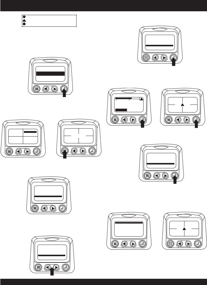
FAULTS ANDWARNINGS
Auxiliary Gage Fault
1.During normal operation the single or four parameter screen will be displayed.
0 |
1500 |
3000 |
98% |
1000 RPM |
|
LOAD RPM |
ENG RPM |
||||
|
|
|
|||
|
1800 RPM |
|
|
||
ENG RPM COOL TEMP |
14.2 |
57 PSI |
|||
BATT VOLT |
OIL PRES |
||||
2.The PVA Series of auxiliary gages can be attached to the PowerView.These auxiliary gages communicate with the Modbus master PowerView via a daisy-chained RS485 port. If at any time during system initialization or normal operation an auxiliary gage should fail, the single or four parameter screen will be replaced with the “MLink Gage Fault” message.
4.Use the “Arrow Buttons” to scroll through the engine configuration data.
ENGINE SPEED PT 1
1800 RPM
 MORE
MORE
5.Touch the “Menu Button” to return to the main menu.
ENGINE SPEED PT 1
1800 RPM
 MORE
MORE
6.Touch the “Menu Button” to exit the Main menu and return to the engine parameter display.
1 of x
ENGINE OIL PRESSURE
GAGE NOT RESPONDING
HIDE
3.To acknowledge and “Hide” the fault and return to the single or four parameter display, touch the “Enter Button”.
1 of x
ENGINE OIL PRESSURE
GAGE NOT RESPONDING
HIDE
4.The display will return to the single or four parameter screen.
|
|
! |
98% |
1000 RPM |
|
0 |
1500 |
3000 |
LOAD RPM |
ENG RPM |
|
|
1800 RPM |
|
! |
|
|
|
|
|
14.2 |
57 PSI |
|
ENG RPM COOL TEMP! |
BATT VOLT |
OIL PRES |
! |
||
|
|
||||
|
|
|
|
|
|
DCA-220SSJ— OPERATION AND PARTS MANUAL — REV. #1 (03/22/07) — PAGE 25
DCA-220SSJ — DIAGNOSTIC DISPLAY
!Indicates Auxiliary Gage Fault
!Indicates Fault Warning
!Indicates Derate or Shutdown Condition Fault
5.Touching the “Enter Button” will redisplay the hidden fault. Touching the “Enter Button” once again will hide the fault and return the screen to the single or four parameter display. NOTE:The fault can only be cleared by correcting the cause of the fault condition.
1 of x
ENGINE OIL PRESSURE
GAGE NOT RESPONDING
HIDE
Active Fault Codes
1. During normal operation the single or four parameter screen will be displayed.
125°F |
1000 RPM |
98% |
1000 RPM |
|
LOAD RPM |
ENG RPM |
|||
COOL TEMP |
ENG RPM |
|
|
|
|
|
|
||
143°F |
57 PSI |
14.2 |
57 PSI |
|
OIL TEMP |
BATT VOLT |
OIL PRES |
||
OIL PRES |
2.When the PowerView receives a fault code from an engine control unit the single or four parameter screen will be replaced with the “Active Fault Codes” message.
1 of x |
WARNING |
SPN110 FMI10
HIGH COOLANT TEMP
 MORE
MORE HIDE
HIDE
3. If the word “MORE” appears above the “Arrow Buttons”, there are more active fault codes that may be viewed. Use the “Arrow Buttons” to scroll to the next “Active Fault Code”.
1 of x
SPN110 FMI10
HIGH COOLANT TEMP
 MORE
MORE HIDE
HIDE
4.To acknowledge and “Hide” the fault and return to the single or four parameter display touch the “Enter Button”.
1 of x
SPN110 FMI10
HIGH COOLANT TEMP
 MORE
MORE HIDE
HIDE
5.The display will return to the single or four parameter display but the display will contain the “Active Fault” warning icon.Touching the “Enter Button” will redisplay the hidden fault.
|
|
! |
98% |
1000 RPM |
|
0 |
1500 |
3000 |
LOAD RPM |
ENG RPM |
|
|
1800 RPM |
|
! |
|
|
|
|
|
14.2 |
57 PSI |
|
ENG RPM COOL TEMP! |
BATT VOLT |
OIL PRES |
! |
||
|
|
||||
|
|
|
|
|
|
6.Touching the “Enter Button” once again will hide the fault and return the screen to the single or four parameter display.
1 of x |
WARNING |
SPN110 FMI10
HIGH COOLANT TEMP
 MORE
MORE HIDE
HIDE
7.The Single or Four parameter screen will display the fault icon until the fault condition is corrected. NOTE: Ignoring active fault codes could result in severe engine damage.
GO TO 1-UP DISPLAY |
98% |
1000 RPM |
|
STORED CODES |
|||
LOAD RPM |
ENG RPM |
||
ENGINE CONFG |
|
|
|
SETUP 1-UP DISPLAY |
|
! |
|
SETUP-4-UP DISPLAY |
14.2 |
57 PSI |
|
SELECT UNITS |
|||
BATT VOLT |
OIL PRES |
||
ADJUST BACKLIGHT |
|
|
PAGE 26 — DCA-220SSJ— OPERATION AND PARTS MANUAL — REV. #1 (03/22/07)
DCA-220SSJ — DIAGNOSTIC DISPLAY
Shut Down Codes
1.During normal operation the single or four parameter screen will be displayed.
5.Touching the “Enter Button” once again will hide the fault and return the screen to the single or four parameter display.
|
|
|
|
|
1 of x |
SHUTDOWN |
|
|
|
|
98% |
1000 RPM |
SPN110 FMI10 |
|
|
0 |
1500 |
3000 |
LOAD RPM |
ENG RPM |
HIGH COOLANT TEMP |
|
|
|
1800 RPM |
|
|
|
MORE |
HIDE |
|
|
|
|
|
|
|
||
|
|
|
14.2 |
57 PSI |
|
|
|
ENG RPM COOL TEMP |
BATT VOLT |
OIL PRES |
|
|
|
||
|
|
|
|
|
|||
2. When the diagnostic display receives a severe fault 6. |
The Single or Four parameter screen will display the |
|||||||
code from an engine control unit the single or four |
fault icon until the fault condition is corrected. NOTE: |
|||||||
Ignoring active fault codes could result in severe engine |
||||||||
parameter screen will be replaced with the “Shutdown” |
||||||||
damage. |
|
|
|
|
||||
message. |
|
|
|
|
|
|||
|
|
|
|
|
|
|
||
1 of x SHUTDOWN |
|
|
|
! |
98% |
1000 RPM |
|
|
|
|
0 |
|
|
||||
|
|
1500 |
3000 |
LOAD RPM |
ENG RPM |
|
||
SPN110 FMI10 |
|
|
1800 RPM |
|
! |
|
||
HIGH COOLANT TEMP |
|
|
|
|
14.2 |
57 PSI |
|
|
MORE |
HIDE |
ENG RPM COOL TEMP! |
|
|||||
BATT VOLT |
OIL PRES |
! |
||||||
|
|
|
|
|
|
|
||
3.To acknowledge and “Hide” the fault and return to the single or four parameter display touch the “Enter Button”.
1 of x SHUTDOWN
SPN110 FMI10
HIGH COOLANT TEMP
 MORE
MORE HIDE
HIDE
4.The display will return to the single or four parameter display, but the display will contain the “Shut Down” icon.Touching the “Enter Button”will redisplay the hidden fault.
0 |
1500 |
! |
98% |
1000 RPM |
3000 |
LOAD RPM |
ENG RPM |
||
|
1800 RPM |
|
! |
|
ENG RPM COOL TEMP! |
14.2 |
57 PSI |
||
BATT VOLT |
OIL PRES |
|||
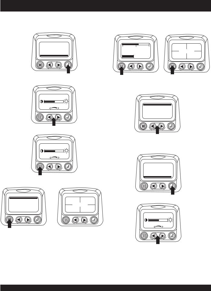
Backlight Adjustment
1.Starting at the single or four engine parameter display touch the “Menu Button”.
|
|
|
98% |
1000 RPM |
0 |
1500 |
3000 |
LOAD RPM |
ENG RPM |
|
1800 RPM |
14.2 |
57 PSI |
|
|
|
|
||
ENG RPM COOL TEMP |
BATT VOLT |
OIL PRES |
||
|
|
|||
2.The main menu will pop up on the display.Use the “Arrow Buttons” to scroll through the menu until the “Adjust Backlight” is highlighted.
GO TO 1-UP DISPLAY
STORED CODES
ENGINE CONFG
SETUP 1-UP DISPLAY
SETUP-4-UP DISPLAY
SELECT UNITS
ADJUST BACKLIGHT
DCA-220SSJ— OPERATION AND PARTS MANUAL — REV. #1 (03/22/07) — PAGE 27
DCA-220SSJ — DIAGNOSTIC DISPLAY
3.Once the “Adjust Backlight” menu item has been highlighted touch the “Enter Button” to activate the
“Adjust Backlight” function.
Contrast Adjustment
1.Starting at the single or four engine parameter display, touch the “Menu Button”.
GO TO 1-UP DISPLAY STORED CODES ENGINE CONFG SETUP 1-UP DISPLAY SETUP-4-UP DISPLAY SELECT UNITS
ADJUST BACKLIGHT
0 |
1500 |
3000 |
98% |
1000 RPM |
|
LOAD RPM |
ENG RPM |
||||
|
|
|
|||
|
1800 RPM |
|
|
||
ENG RPM COOL TEMP |
14.2 |
57 PSI |
|||
BATT VOLT |
OIL PRES |
||||
4. Use the “Arrow Buttons” to select the desired backlight |
2. The main menu will pop up on the display.Use the “Arrow |
intensity. |
Buttons” to scroll through the menu until “Adjust Contrast” |
|
|
|
is highlighted. |
ADJUST BACKLIGHT |
|
|
GO TO 1-UP DISPLAY |
|
STORED CODES |
|
ENGINE CONFG |
|
SETUP 1-UP DISPLAY |
|
SETUP-4-UP DISPLAY |
|
SELECT UNITS |
|
ADJUST BACKLIGHT |
5.Touch the “Menu Button” to return to the main menu.
ADJUST BACKLIGHT
6.Touch the “Menu Button” to exit the Main menu and return to the engine parameter display.
3.Once the “Adjust Contrast” menu item has been highlighted touch the “Enter Button” to activate the “Adjust Contrast” function.
STORED CODES
ENGINE CONFG
SETUP 1-UP DISPLAY
SETUP-4-UP DISPLAY
SELECT UNITS
ADJUST BACKLIGHT
ADJUST CONTRAST
GO TO 1-UP DISPLAY
STORED CODES
ENGINE CONFG SETUP 1-UP DISPLAY SETUP-4-UP DISPLAY SELECT UNITS ADJUST BACKLIGHT
98% |
1000 RPM |
LOAD RPM |
ENG RPM |
14.257 PSI
BATT VOLT |
OIL PRES |
4.Use the “Arrow Buttons” to select the desired contrast intensity.
ADJUST CONTRAST
5.Touching the “Menu Button” will take you back through the menus.
PAGE 28 — DCA-220SSJ— OPERATION AND PARTS MANUAL — REV. #1 (03/22/07)
DCA-220SSJ — DIAGNOSTIC DISPLAY
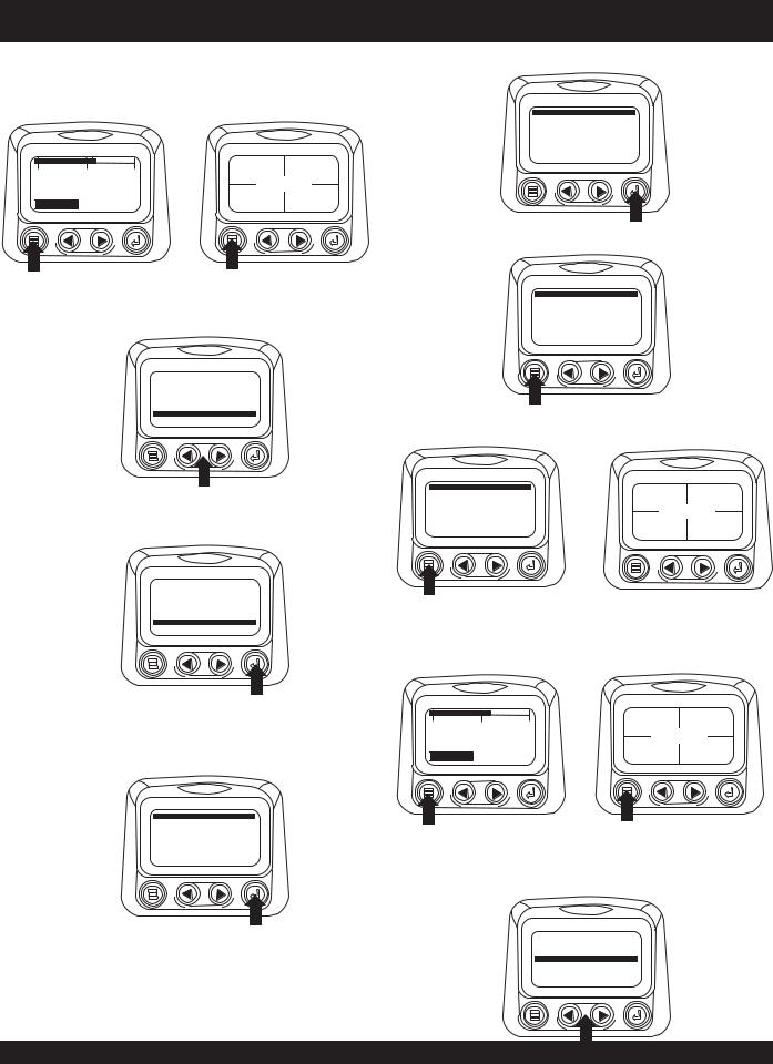
Select Units
1.Starting at the single or four engine parameter display touch the “Menu Button”.
5.Touch the “Enter Button” to select the highlighted units.
ENGLISH
METRIC KPA
METRIC BAR
|
|
|
98% |
1000 RPM |
0 |
1500 |
3000 |
LOAD RPM |
ENG RPM |
1800 RPM
|
14.2 |
57 PSI |
ENG RPM COOL TEMP |
BATT VOLT |
OIL PRES |
|
|
6. Touch the “Menu Button” to return to the “Main Menu”.
2.The main menu will pop up on the display.Use the arrow buttons to scroll through the menu until the “Select Units” is highlighted.
ENGLISH |
* |
METRIC KPA |
|
METRIC BAR |
|
GO TO 1-UP DISPLAY STORED CODES ENGINE CONFG SETUP 1-UP DISPLAY SETUP-4-UP DISPLAY
SELECT UNITS
ADJUST BACKLIGHT
7.Touch the “Menu Button” to exit the Main menu and return to the engine parameter display.
3.Once the “Select Units” menu item has been highlighted touch the “Enter Button” to access the “Select Units” function.
GO TO 1-UP DISPLAY
STORED CODES
ENGINE CONFG
SETUP 1-UP DISPLAY
SETUP-4-UP DISPLAY
SELECT UNITS
ADJUST BACKLIGHT
GO TO 1-UP DISPLAY |
|
1000 RPM |
STORED CODES |
98% |
|
ENGINE CONFG |
LOAD RPM |
ENG RPM |
|
|
|
SETUP 1-UP DISPLAY |
|
|
SETUP-4-UP DISPLAY |
14.2 |
|
SELECT UNITS |
57 PSI |
|
ADJUST BACKLIGHT |
BATT VOLT |
OIL PRES |
|
|
Setup 1- Up Display
1.Starting at the single engine parameter display, touch the “Menu Button”.
4. Use the arrows to highlight the desired units. “English” |
|
|
|
98% |
1000 RPM |
for imperial units i.e. PSI,”F or Metric kPa, Metric Bar |
0 |
1500 |
3000 |
LOAD RPM |
ENG RPM |
|
1800 RPM |
|
|
||
for IS units i.e. kPa, Bar, “C. |
ENG RPM COOL TEMP |
14.2 |
57 PSI |
||
BATT VOLT |
OIL PRES |
||||
ENGLISH
ESPANOL FRANCAIS DEUTSCH
2.The main menu will pop up on the display. Use the “Arrow Buttons” to scroll through the menu until the “Setup 1-up Display” is highlighted.
GO TO 1-UP DISPLAY STORED CODES ENGINE CONFG
SETUP 1-UP DISPLAY
SETUP-4-UP DISPLAY SELECT UNITS ADJUST BACKLIGHT
DCA-220SSJ— OPERATION AND PARTS MANUAL — REV. #1 (03/22/07) — PAGE 29
DCA-220SSJ — DIAGNOSTIC DISPLAY
3. Once the “Setup 1-up Display” menu icon has been 7. |
A message indicating the “Single Engine” parameter |
highlighted touch the “Enter Button” to access the “Setup |
display parameters are reset to the factory defaults will |
1-up display” function. |
be displayed, then the display will return to the “Custom |
|
Setup” menu. |
GO TO 1-UP DISPLAY STORED CODES ENGINE CONFG
SETUP 1-UP DISPLAY
SETUP-4-UP DISPLAY SELECT UNITS ADJUST BACKLIGHT
RESTORED TO
DEFAULTS
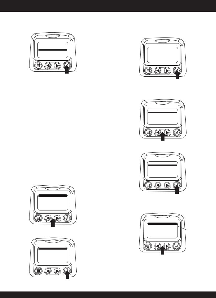
4.Three options are available for modification of the 1-Up display.
a). Use defaults-This option contains a set of engine parameters: Engine Hours, Engine RPM. System Voltage, BatteryVoltage, % Engine Load at Current
RPM, Coolant Temperature, Oil Pressure.
b). Custom Setup- This option allows for the modification of what parameter, the number of parameters, and the order in which the parameters are being displayed.
c). Automatic scan - Selecting the scan function will cause the 1-Up Display to scroll through the selected set of parameters one at a time, momentarily pausing at each.
5.Use DefaultsTo select “Use Defaults” use the arrow buttons to scroll to and highlight “Use Defaults” in the menu display.
8.Custom SetupTo perform a custom setup of the 1-Up Display, use the arrow buttons to scroll to and highlight “Custom Setup” on the display.
USE DEFAULTS
CUSTOM SETUP
AUTOMATIC SCAN OFF
9.Touching the “Enter Button” will display a list of engine parameters.
USE DEFAULTS
CUSTOM SETUP
AUTOMATIC SCAN OFF
USE DEFAULTS
CUSTOM SETUP AUTOMATIC SCAN OFF
10.Use the “Arrow Buttons” to scroll to and highlight a selected parameter (parameter with a # symbol to right of it).
6.Touch the “Enter Button” to activate the “Use Defaults” function.
USE DEFAULTS
CUSTOM SETUP
AUTOMATIC SCAN OFF
ENGINE SPEED |
1 |
PERCENT LOAD AT CURRENT RPM 3 |
|
ENGINE OIL PRESSURE |
2 |
ENGINE COOLANT TEMPERATURE |
|
This number indicates the order of display for the parameters and that the parameter is selected
for display.
PAGE 30 — DCA-220SSJ— OPERATION AND PARTS MANUAL — REV. #1 (03/22/07)
 Loading...